Rosemount 2120 User manual

Quick Start Guide
00825-0100-4030, Rev BA
August 2012
Rosemount 2120 Full-featured
Vibrating Fork Liquid Level Switch

August 2012
2
Quick Start Guide
NOTICE
This installation guide provides basic guidelines for the Rosemount 2120. It does not provide
instructions for detailed configuration, diagnostics, maintenance, service, troubleshooting,
or installations. Refer to the Rosemount 2120 Reference Manual (Document Number
00809-0100-4030) for more instruction. Manuals are available electronically on
www.rosemount.com.
Failure to follow these installation guidelines could result in death or serious injury
The Rosemount 2120 is a liquid level switch. It must be installed, connected, commissioned,
operated, and maintained by suitably qualified personnel only, observing any national and
local requirements that may apply
Ensure the wiring is suitable for the electrical current and the insulation is suitable for the
voltage, temperature, and environment
Use the equipment only as specified. Failure to do so may impair the protection provided by
the equipment
Any substitution of non-recognized parts may jeopardize safety and is under no
circumstances allowed
Explosions could result in death or serious injury
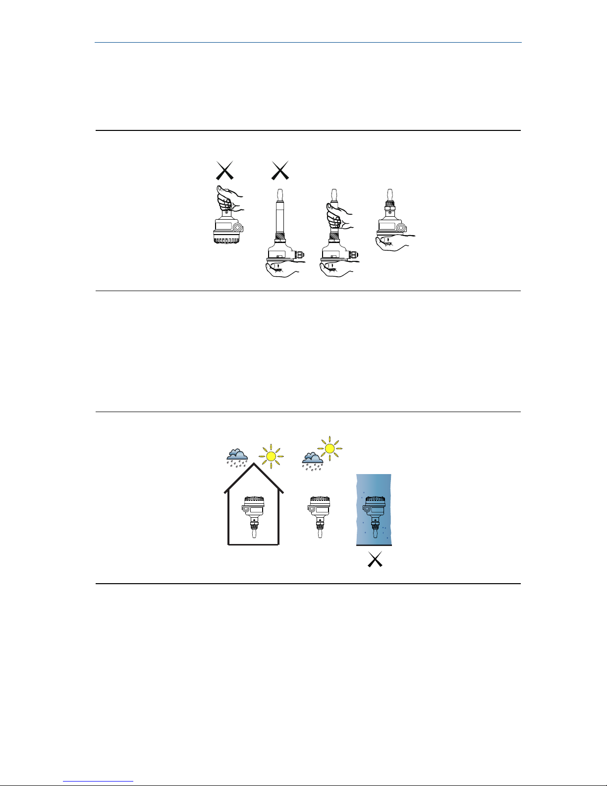
Installation of the 2120 in a hazardous environment must be in accordance with the
appropriate local, national, and international standards, codes, and practices. Please review
the Product Certifications section for any restrictions associated with a safe installation
Verify that the operating atmosphere of the 2120 is consistent with the appropriate
hazardous locations certifications
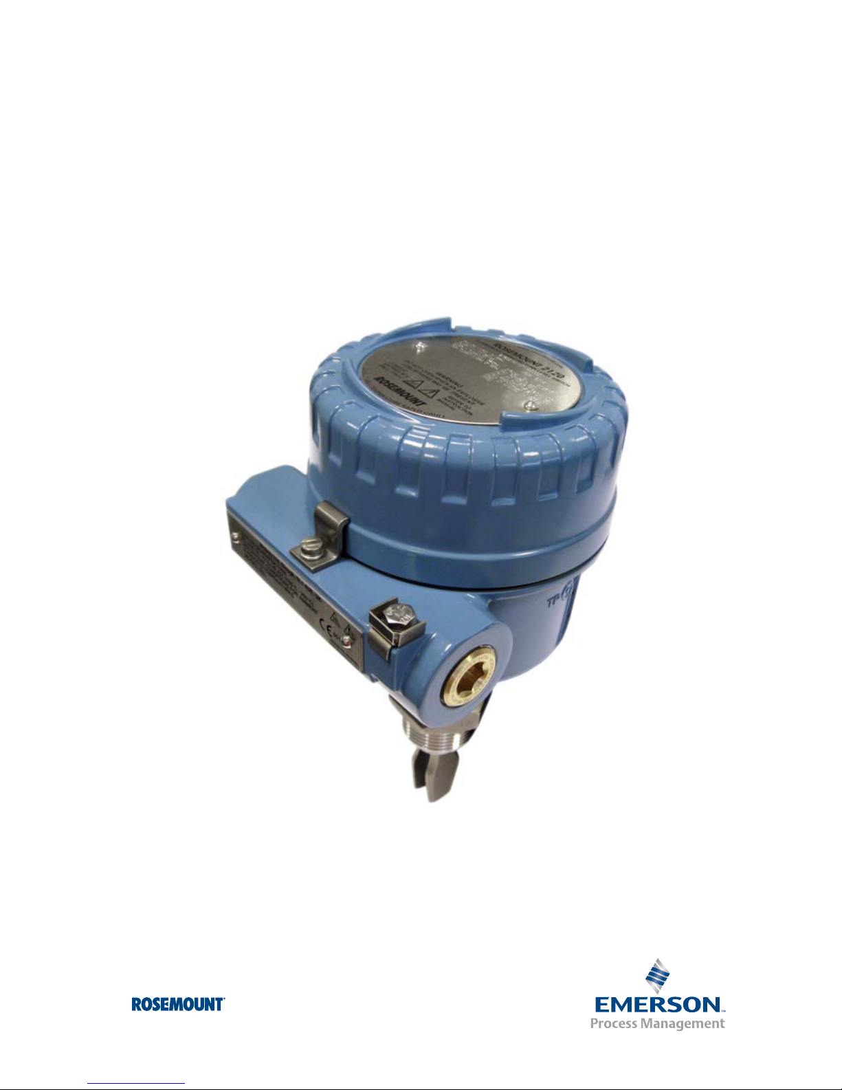
External surface may be hot
Care must be taken to avoid possible burns
Process leaks could result in death or serious injury
Install and tighten process connectors before applying pressure
Do not attempt to loosen or remove process connectors while the 2120 is in service
Electrical shock could cause death or serious injury
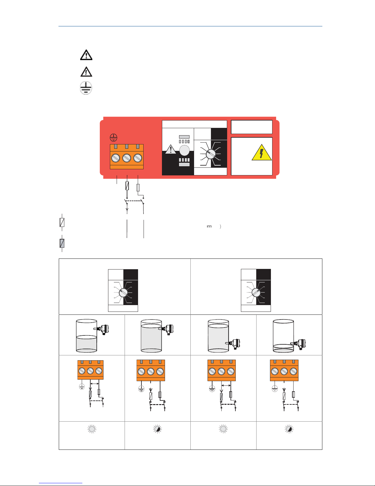
If the liquid level switch is installed in a high voltage environment and a fault condition or
installation error occurs, high voltage may be present on leads and terminals
Use extreme caution when making contact with the leads and terminals
Make sure that power to the 2120 is off while making connections

Quick Start Guide
3
August 2012
Overview of the Rosemount 2120
The Rosemount 2120 is a liquid point level switch. Based on vibrating short fork
technology, the 2120 is suitable for virtually all liquid applications.
The Rosemount 2120 is designed using the principle of a tuning fork. A piezo-electric
crystal oscillates the forks at their natural frequency (~1400 Hz). Changes to this
frequency are continuously monitored. The frequency of the vibrating fork sensor
changes depending on the medium in which it is immersed. The denser the liquid, the
lower the frequency.
When used as a low level alarm, the liquid in the tank or pipe drains down past the fork,
causing a change of natural frequency that is detected by the electronics and switches
the output state to a Dry condition. When the 2120 switch is used as a high level
alarm, the liquid rises in the tank or pipe, making contact with the fork which then
causes the output state to switch to a Wet condition.
The 2120 has a ‘heartbeat’ LED that indicates its operating state. The LED flashes when
the switch output is ‘off’ and is constantly lit when 'on'.
Figure 1. Rosemount 2120 features
A. Visible heartbeat LED G. Wetted material in 316/316L SST, solid
B. Mode switch, adjustable time delay Alloy C and Alloy C-276, or
C. Housings in glass-filled nylon, ECTFE/PFA-coated 316/316L SST
aluminum, or 316 SST H. Short fork length or extensions up to
D. Magnetic test point 157.5-in. (4 m)
E. Threaded, Flanged, or Hygienic Connections I. Two cable/conduit entries
F. ‘Fast drip’ fork design J. Direct Load, Relay DPCO, PLC/PNP,
NAMUR, or 8/16 mA electronics
F
B
A
G
H
C
I
J
E
D

August 2012
4
Quick Start Guide
General considerations
Handle the Rosemount 2120 with great care. Use both hands when carrying the
extended length versions. Do not hold the 2120 using the forks
Do not alter the 2120 in any way
Figure 2. How to handle the Rosemount 2120
The 2120 is available as intrinsically safe or explosion-proof/flameproof versions
for hazardous area installations (see page 16 for approvals)
There are ordinary location versions of the 2120 for unclassified, safe areas
This liquid level switch is designed for open or closed tanks, and pipe installation. It
is weatherproof and protected against the ingress of dust, but must be protected
from flooding (Figure 3)
The 2120 operates in process temperatures of –40 to 302 °F (–40 to 150 °C)
Figure 3. Environmental considerations
Ensure there is adequate space outside the tank or pipe. A clearance of 1.2 in.
(30 mm) is required for the cover to be removed
Always ensure a proper seal by installing the electronics metal housing cover so
that metal contacts metal, or plastic contacts plastic. Use Rosemount O-rings
Always ground the housing in accordance with national and local electrical codes.
The most effective grounding method is a direct connection to earth (ground)
with minimal impedance. Use the fork earth for metal housings with NPT conduit
entries
OK OK
OKOK

Quick Start Guide
5
August 2012
Installation recommendations
Avoid installing near liquid entering the tank at the fill point
Avoid heavy splashing on the forks.
Increasing the time delay reduces accidental switching
Avoid installing near heat sources
Ensure the fork does not come into contact with the tank/pipe wall, or fittings
Allow a sufficient distance between product build-up on the tank wall and fork
Figure 4. Avoid product build-up around the forks
Step 1: Physical installation
1. Install the 2120 according to standard installation practices, making sure to
correctly align the fork using the alignment notch or groove (Figure 6).
2. Use supports for extended fork lengths greater than 3.2 ft. (1 m) (Figure 5).
For the GL approval requirements, see reference manual 00809-0100-4030.
3. Close the housing cover and tighten to safety specification. Always ensure a proper
seal so that metal touches metal or plastic touches plastic, but do not over tighten.
4. Insulate the 2120 with Rockwool. See Figure 7 for clearances.
Figure 5. Supports needed for an extended fork (standard)
OK
3.2ft.
(1 m)
3.2 ft.
(1 m)
3.2 ft.
(1 m)
3.2ft.
(1 m)
Max. 3.2 ft. (1 m)
Max.
3.2 ft.
(1 m)

August 2012
6
Quick Start Guide
Figure 6. Example installations
A. PTFE for NPT and BSPT (R) Thread
B. Gasket for BSPP (G) Thread
C. Fork Alignment Groove
D. Fork Alignment Notch
E. Fork Alignment Notch
A
E
C
B
D
Threaded 2120
installation
Flanged 2120
installation
D

Quick Start Guide
7
August 2012
Figure 7. Insulation
A. 3.9 in. (100 mm) Clearance All Around
B. 5.9 in. (150 mm)
C. Rockwool
AA
B
C

August 2012
8
Quick Start Guide
Step 2: Electrical installation
Before use, check that suitable cable glands and blanking plugs are fitted and
fully tightened.
Isolate supply before connecting the switch or removing the electronics.
The functional earth terminal must be connected to an external
earthing system.
Direct load switching electronics cassette (two-wire, red label)
High level Dry = ON Low level Wet = ON
LED on continuously LED flashes each
second LED on continuously LED flashes each
second
Direct Load
Switching
WARNING
Isolate Supply
Before Removing
OPERATION MODE
Dry On Mode
Dry
Wet
Wet On Mode
Dry
Wet
Dry On Wet On
Seconds Delay
0.3 0.3
3
30
10
1
3
30
10
1
123
LINE
LOAD
PE
(Ground)
Neutral Live
0V
Fuse 2A(T)
R
I
L
R = External load (must be fitted)
U = 20 - 264V ~(ac) (50/60Hz)
I
OFF
< 4
mA
I
L
=
20 -
500
mA
U = 20 - 60V (dc
)
)
I
OFF
< 4 mA
IL
=
20 -
500 mA
DPST
+V
= 5 A, 40 ms (inrush)
I
PK
= 5 A, 40 ms (inrush)
I
PK
= Load On
= Load Off
Note: The values
shown are nominal;
see the 2120
Reference Manual
00809-0100-4030
for complete data
Dry On Wet On
Seconds Delay
0.3 0.3
3
30
10
1
3
30
10
1
Dry On Wet On
Seconds Delay
0.3 0.3
30
10 3
30
10
1
3
1
U
N L
0V +V
Fuse
2A(T)
I
L
12V
DPST
Fuse
2A(T)
N L
0V +V
IL
<4mA
DPST
U
N L
0V +V
Fuse
2A(T)
IL12V
DPST
Fuse
2A(T)
N L
0V +V
IL
<4mA
DPST

Quick Start Guide
9
August 2012
PNP/PLC electronics cassette (three-wire, yellow label)
High level Dry = ON Low level Wet = ON
PLC (positive input)PNP dc
LED on
continuously
LED flashes each
second LED on
continuously LED flashes each
second
OPERATION MODE
Dry On Mode
Dry
Wet
Wet On Mode
Dry
Wet
Dry On Wet On
Seconds Delay
0.3 0.3
3
30
10
1
3
30
10
1
123
OUT
+-
4
PLC/PNP
Isolate Supply
Before Removing
PE
(Ground)
0VO/P
U = 20- 60 V (dc)
I < 4 mA + I
L
I
L
(
MAX
)= 0 -500 mA
U
OUT(ON)
=
U
-
2.5 V
I
L(OFF)
< 100A
+V
Fuse 2A(T)
= 5 A, 40 ms (inrush)
I
PK
Note: The values
shown are nominal;
see the 2120
Reference Manual
00809-0100-4030
for complete data
Dry On Wet On
Seconds Delay
0.3 0.3
3
30
10
1
3
30
10
1
Dry On Wet On
Seconds Delay
0.3 0.3
30
10 3
30
10
1
3
1
OUT
-
+
PLC
+
I/P
U
<3V I
L
OUT
-
+
PLC
+
I/P
I
L
<100 A
OUT
-
+
PLC
+
I/P
U
<3V I
L
OUT
-
+
PLC
+
I/P
I
L
<100 A
OUT
-
+
+
U
<3V
I
L
Fuse
1A(T)
R
OUT
-
+
+
I
L
Fuse
1A(T)
R
< 100 A
OUT
-
+
+
U
<3V
I
L
Fuse
1A(T)
R
OUT
-
+
+
I
L
Fuse
1A(T)
R
< 100 A

August 2012
10
Quick Start Guide
Relay output electronics cassette (DPCO, green label)
High level Dry = ON Low level Wet = ON
LED on continuously LED flashes each
second LED on continuously LED flashes each
second
NC CNO
NC NO
789
NOCNC
RELAY
123
LN
456
NOCNC
OPERATION MODE
Dry On
Dry
Wet
Wet On
Dry
Wet
Dry On Wet On
Seconds Delay
30
10
3
1
0.3 0.3
30
10
3
1
Isolate Supply Before RemovingWarning
C
Resistive Load
cos φ= 1 ;
L/R = 0 ms
ac
dc
Inductive Load
Fuse 0.5 (T)PE
(Ground)
DPST
N
0V +V
Live U = 20...264 V ~ (ac)
(50/60 Hz)
U = 20...60 V (dc)
I < 6 mA
I < 6 mA
IMAX = 5 A
UMAX = 250 V
PMAX = 1250 VA
UMAX = 30 V
PMAX = 240 W
cos φ= 0.4 ;
L/R = 7 ms
ac
dc
IMAX = 3.5 A
UMAX = 250 V
PMAX = 875 VA
UMAX = 30 V
PMAX = 170W
Dry On Wet On
Seconds Delay
0.3 0.3
3
30
10
1
3
30
10
1
Dry On Wet On
Seconds Delay
0.3 0.3
30
10 3
30
10
1
3
1
NC NOCNC NOC
NC NOC
NC NOC
NC NOCNC NOCNC NOC
NC NOC

Quick Start Guide
11
August 2012
NAMUR electronics cassette (light blue label)
Note
This cassette is suitable for Intrinsically Safe applications and requires an isolating
barrier. See “Product Certifications” on page 16 for Intrinsically Safe approvals
This electronics cassette is also suitable for non-hazardous (safe) area applications.
It can only be interchanged with the 8/16 mA cassette.
Do not exceed 8 Vdc
High level Dry = ON Low level Wet = ON
LED on continuously LED flashes each
second
LED on continuously LED flashes each
second
OPERATION MODE
Dry On Mode
Dry
Wet
Wet On Mode
Dry
Wet
Dry On Wet On
Seconds Delay
0.3 0.3
3
30
10
1
3
30
10
1
12
+-
EN 50227 / NAMUR
ION =2.2 ... 2.5 mA
IOFF = 0.8 ... 1.0 mA
+
-
A certified intrinsically safe
isolating amplifier to IEC 60947-5-6
Ex
Ex
8V
dc
Dry On Wet On
Seconds Delay
0.3 0.3
3
30
10
1
3
30
10
1
Dry On Wet On
Seconds Delay
0.3 0.3
30
10 3
30
10
1
3
1
+
-
>2.2 mA
+
-
<1.0 mA
+
-
>2.2 mA
+
-
<1.0 mA

August 2012
12
Quick Start Guide
8/16 mA electronics cassette (dark blue label)
Note
This cassette is suitable for Intrinsically Safe applications and requires an isolating
barrier. See “Product Certifications” on page 16 for Intrinsically Safe approvals
This cassette is also suitable for non-hazardous (safe) area applications. It can only be
interchanged with a NAMUR cassette
High level Dry = ON Low level Wet = ON
LED on continuously LED flashes each
second LED on continuously LED flashes each
second
OPERATION MODE
Dry On Mode
Dry
Wet
Wet On Mode
Dry
Wet
Dry On Wet On
Seconds Delay
0.3 0.3
3
30
10
1
3
30
10
1
8/16 mA
123
+
Drives 4-20 mA Analog Input
I
ON
=
I
OFF
=
+
-
+
A certified intrinsically safe barrier
must be used to meet IS requirements
Ex
Ex
15 . .. 17 mA
7.5 … 8.5 mA
-
Earth
(Ground)
U
=
24 Vdc Nominal
Dry On Wet On
Seconds Delay
0.3 0.3
3
30
10
1
3
30
10
1
Dry On Wet On
Seconds Delay
0.3 0.3
30
10 3
30
10
1
3
1
+
> 15 mA
+
< 8.5 mA
+
> 15 mA
+
< 8.5 mA

Quick Start Guide
13
August 2012
Step 3: Set mode switch and switching time delay
1. Select “Dry on” or “Wet on” mode.
2. Select 0.3, 1, 3, 10, or 30 seconds for the delay before switching output state.
Note
There is a five second delay when changing mode or time delay
The small cut-out in the rotating switch indicates time delay and mode
Recommended installation for a high level alarm is “Dry on” and for a low level alarm it is
“Wet on”. Do not install in the normally ‘off’ state
Figure 8. Top-down view of example cassette inside the housing
A. LED
B. Mode Switch and Time Delay
LED indication
When the LED is red and flashing, it indicates the 2120 may be uncalibrated,
successfully calibrated, has an electrical load problem, or has an internal PCB fault.
See Table 1 for further information.
Table 1. LED flash rate
LED Flash Rate Switch Status
Continuous Output state is on
1 every second Output state is off
1 every 2 seconds Uncalibrated1
1. Refer to the “Replacement and Calibration of Electronic Cassettes” section in the 2120 Reference Manual
(00809-0100-4030) or Manual Supplement (00809-0200-4030).
1 every 4 seconds Load fault; load current too high; load short circuit
2 times every second Indication of successful calibration
3 times every second Internal PCB fault (microprocessor, ROM, or RAM)
Off Problem (e.g. supply)
OPERATION MODE
Dry On Mode
Dry
Wet
Wet On Mode
Dry
Wet
Dry On Wet On
Seconds Delay
0.3 0.3
3
30
10
1
3
30
10
1
123
OUT
+-
4
PLC/PNP
Isolate Supply
Before Removing
B
A

August 2012
14
Quick Start Guide
Step 4: Verify operation
Magnetic test point
The magnetic test-point is on the side of the housing, allowing a functional test of the
2120. By touching a magnet on the target, the output will change state for as long as
the magnet is held there.
Figure 9. Magnetic test point (metal housing)
Figure 10. Magnetic test point (glass-filled nylon housing)
TP TP
TP
N
S
N
S
(OUTPUT ON)
(OUTPUT ON)
(OUTPUT OFF)
(OUTPUT OFF)
NO MAGNET MAGNET
(OUTPUT ON)
(OUTPUT ON)
(OUTPUT OFF)
(OUTPUT OFF)
NO MAGNET MAGNET

Quick Start Guide
15
August 2012
Maintenance
Only use a soft brush for cleaning.
Inspection
Visually examine the 2120 for damage. If it is damaged, do not use
Ensure the housing cover, cable glands, and blanking plugs are fitted securely
Ensure the LED flash rate is 1 Hz or continually on.
(See “LED indication” on page 13)
Spare Parts
See the 2120 Product Data Sheet 00809-0100-4030 for spares and accessories
Troubleshooting
Table 2. Troubleshooting chart
Fault Symptom/Indication Action/Solution
Does not
switch
No LED; no power Check the power supply; (check load on direct
load switching electronics model)
LED flashing See “LED indication” on page 13
Fork is damaged Replace the 2120
Thick encrustation on the forks Clean the fork with care
5 second delay when changing
mode/delay This is normal – wait 5 seconds
Incorrect
switching Dry = On, Wet = On set correctly Set the correct mode on the electronics cassette
Faulty
switching
Turbulence Set a longer switching time delay
Excessive electrical noise Suppress the cause of the interference
Cassette has been fitted from another
Rosemount 2120
Fit the factory supplied cassette
and then calibrate1
1. Refer to the “Replacement and Calibration of Electronic Cassettes” section in the 2120 Reference Manual
(00809-0100-4030) or Manual Supplement (00809-0200-4030).

August 2012
16
Quick Start Guide
Product Certifications
European Directive Information
The EC declaration of conformity for all applicable European directives for this product
can be found on page 28 and on the Rosemount website at www.rosemount.com.
A hard copy may be obtained by contacting your local sales office.
ATEX Directive (94/9/EC)
Complies with the ATEX Directive.
Pressure Equipment Directive (PED) (97/23/EC)
The Rosemount 2120 is outside the scope of the PED Directive.
L.V. Directive
EN61010-1 Pollution degree 2, Category II (264 V maximum),
Pollution degree 2, Category III (150 V maximum)
Electro Magnetic Compatibility (EMC) Directive
EN61326 Emissions to Class B. Immunity to industrial location requirements.
CE-mark
Complies with applicable directives (EMC, ATEX, and LVD)
Ordinary location certification for FM
G5 Project ID: 3021776
The switch has been examined and tested to determine that the design meets basic
electrical, mechanical, and fire protection requirements by FM, a nationally recognized
testing laboratory (NRTL) as accredited by the Federal Occupational Safety and Health
Administration (OSHA).
Ordinary location certification for CSA
G6 Certificate Number: 06 CSA 1805769
The switch has been examined and tested to determine that the design meets basic
electrical, mechanical, and fire protection requirements by CSA, a nationally recognized
testing laboratory as accredited by the Standards Council of Canada (SCC).
Single Seal
Canadian Registration Number
Certificate Number CRN 0F04227.2C
The requirements of CRN are met when a 2120 vibrating fork level switch is configured
with 316/316L stainless steel (1.4401/1.4404) wetted parts and either NPT threaded
or 2-in. to 8-in. ASME B16.5 flanged process connections.

Quick Start Guide
17
August 2012
Hazardous locations certifications
Note
Acertified isolating amplifier to IEC 60947-5-6 is required for intrinsic safety if the
NAMUR electronics is used in a hazardous area installation
A certified intrinsically safe barrier is required for intrinsic safety if the 8/16 mA
electronics is used in a hazardous area installation
North American and Canadian approvals
Factory Mutual (FM) explosion-proof approval
(See “Instructions for hazardous area installations (E5 and E6)” on page 19)
E5 Project ID: 3012658
Explosion-proof for Class I, Div. 1, Groups A, B, C, and D
Temperature Class: T6 (Tamb –40 to 75 °C)
Enclosure: Type 4X
Factory Mutual (FM) intrinsically safe approval
(See “Instructions for hazardous (classified loc.) area installations (I5 and I6)” on page 21)
I5 Project ID: 3011456
Intrinsically Safe for Class I, Div. 1, Groups A, B, C, and D
Class I, Zone 0, AEx ia IIC
Temperature Code: (Tamb –40 to 80 °C, Tproc < 80 °C)
Control Drawing: 71097/1154 (with NAMUR electronics)
Control Drawing: 71097/1314 (with 8/16 mA electronics)
Canadian Standards Association (CSA) explosion-proof approval
(See “Instructions for hazardous area installations (E5 and E6)” on page 19)
E6 Project ID: 1786345
Explosion-proof for Class I, Div. 1, Groups A, B, C, and D
Temperature Class: T6 (Tamb –40 to 75 °C)
Enclosure: Type 4X
Single Seal
Canadian Standards Association (CSA) intrinsically safe approval
(See “Instructions for hazardous (classified loc.) area installations (I5 and I6)” on page 21)
I6 Certificate Number: 06 CSA 1786345
Intrinsically Safe for Class I, Div. 1, Groups A, B, C, and D
Class I, Zone 0, Ex ia IIC
Temperature Code: T5 (Tamb –40 to 80 °C, Tproc < 80 °C)
Control Drawing: 71097/1179 (with NAMUR electronics)
Control Drawing: 71097/1315 (with 8/16 mA electronics)
Single Seal
Canadian Standards Association (CSA) non-incendive approval
(See “Instructions for hazardous (classified loc.) area installations (I5 and I6)” on page 21)
I6 Certificate Number: 06 CSA 1786345
Non-Incendive for Class I, Div. 2, Groups A, B, C, and D
Temperature Code: T5 (Tamb –40 to 80 °C, Tproc < 80 °C)
Control Drawing: 71097/1179 (with NAMUR electronics)
Control Drawing: 71097/1315 (with 8/16 mA electronics)
Single Seal

August 2012
18
Quick Start Guide
European approvals
ATEX approvals
E1 Certificate: Sira 05ATEX1129X
Flameproof and Dust:
ATEX Marking II 1/2 G D
Ex d IIC T6...T2 Ga/Gb
Ex tb IIIC T85 °C...T265 °C Db
(See “Instructions specific to hazardous area installations (E1 and E7)” on page 23)
I1 Certificate: Sira 05ATEX2130X
Intrinsic Safety and Dust:
ATEX Marking II 1 G D
Ex ia IIC T5...T2 Ga
Ex ia IIIC T85 °C...T265 °C Da
(See “Instructions specific to hazardous area installations (I1 and I7)” on page 25)
Rest of the world approvals
International Electrotechnical Commission (IEC) approvals
E7 Certificate: IECEx SIR 06.0051X
Flameproof and Dust:
Ex d IIC T6...T2 Ga/Gb
Ex tb IIIC T85 °C...T265 °C Db
(See “Instructions specific to hazardous area installations (E1 and E7)” on page 23)
I7 Certificate: IECEx SIR 06.0070X
Intrinsically Safe and Dust:
Ex ia IIC T5...T2 Ga
Ex ia IIIC T85 °C...T265 °C Da
(See “Instructions specific to hazardous area installations (I1 and I7)” on page 25)
Note
A certified isolating amplifier to IEC 60947-5-6 is required for intrinsic safety if the
NAMUR electronics is used in a hazardous area installation
A certified intrinsically safe barrier is required for intrinsic safety if the 8/16 mA
electronics is used in a hazardous area installation

Quick Start Guide
19
August 2012
Instructions for hazardous area installations (E5 and E6)
Model numbers covered:
2120*****E5Y**, 2120*****E5T**, 2120*****E6Y**, 2120*****E6T**
(“*” indicates options in construction, function and materials).
The following instructions apply to equipment covered by CSA and FM explosion-proof
approvals:
1. The equipment may be used with flammable gases and vapors with apparatus
Class 1, Div 1, Groups A, B, C and D.
2. CSA and FM Explosion Proof approved versions of the 2120 are certified for use in
ambient temperatures of –40 °F to 176 °F (–40 °C to 80 °C), and with a maximum
process temperature of 302 °F (150 °C).
3. Installation of this equipment shall be carried out by suitably trained personnel, in
accordance with the applicable code of practice.
4. Inspection and maintenance of this equipment shall be carried out by suitably
trained personnel, in accordance with the applicable code of practice.
5. The user should not repair this equipment.
6. The certification of this equipment relies upon the following materials used in its
construction:
Body: Aluminum Alloy (ASTM B85 360.0) or 316 SST
Lid: Aluminum Alloy (ASTM B85 360.0) or 316 SST
Probe: 316 Stainless Steel, or Alloy C276 (UNS N10276) and Alloy C (UNS N10002)
Probe Filling: Perlite
Lid Seal: Silicone
If the equipment is likely to come into contact with aggressive substances, it is the
responsibility of the user to take suitable precautions that prevent it from being
adversely affected, thus ensuring that the type of protection is not compromised.
Aggressive Substances – e.g. acidic liquids or gases that may attack metals or
solvents that may affect polymeric materials.
Suitable Precautions – e.g. regular checks as part of routine inspections or
establishing from the material’s data sheet that it is resistant to specific chemicals.
The metallic alloy used for the enclosure material may be at the accessible surface
of this equipment; in the event of rare accidents, ignition sources due to impact
and friction sparks could occur. This shall be considered when the 2120 is installed
in locations that specifically require Class 1, Div 1 equipment.
7. It is the responsibility of the user to ensure:
a. The voltage and current limits for this equipment are not exceeded.
b. That the joint requirements between the switch and the vessel tank are
compatible with the process media.
c. That the joint tightness is correct for the joint material used.
d. That only certified cable entry devices will be used when connecting this
equipment.
e. That any unused cable entries are sealed with suitably certified stopping plugs.
8. The switch fork is subjected to small vibration stresses as part of its normal
function. As this provides a partition wall, it is recommended that the fork should
be inspected every 2 years for signs of defects.

August 2012
20
Quick Start Guide
9. Technical data:
a. Coding: Class 1, Div 1, Groups A, B, C, and D
b. Temperature:
2120*****E5Y**, 2120*****E5T**, 2120*****E6Y**, 2120*****E6T**:
Minimum ambient air temperature (Ta) = –40 °C
Minimum process temperature (Tp) = –40 °C
c. Pressure: Must not exceed the rating of the coupling/flange fitted.
d. For electrical details and pressure ratings, see the 2120 Product Data Sheet
00813-0100-4030 or Reference Manual 00809-0100-4030.
10. Cable selection:
a. It is the responsibility of the user to ensure that suitably temperature rated cable
is used. The table below is a guide to selection:
Temperature
Classes
Maximum Ambient Air
Temperature (Ta)
Maximum Process
Temperature (Tp)
T6, T5, T4, T3, T2, T1 75 °C75 °C
T5, T4, T3, T2, T1 70 °C95 °C
T4, T3, T2, T1 65 °C125 °C
T3, T2, T1 50 °C150 °C
T Class Cable Temperature Rating
T6 Above 185 °F (85 °C)
T5 Above 212 °F (100 °C)
T4 Above 275 °F (135 °C)
T3 Above 320 °F (160 °C)
Other manuals for 2120
1
Table of contents
Popular Switch manuals by other brands

GESTRA
GESTRA NRS 1-41 Original Installation Instructions

Sony
Sony CAV-CVS12ES - Component Video Switcher manual

Eaton
Eaton Cutler-Hammer AMPGARD instructions

Siemens
Siemens RUGGEDCOM RS900F installation manual

NETGEAR
NETGEAR S3600 Series installation guide

steute
steute ZS 92 S EXTREME Series Mounting and wiring instructions

AURES
AURES HUB-RETAIL-KL18.1 product manual

Elko
Elko inels RFUS-11 quick start guide

Brocade Communications Systems
Brocade Communications Systems SilkWorm 2400 Hardware reference manual

ZyXEL Communications
ZyXEL Communications ZyXEL Dimension GS-1008 user guide

Aegis
Aegis 4KPROIP-CBS quick start guide

ATEN
ATEN ALTUSEN KW1000 quick start guide