Rosen 6500 User manual

6500
6500
6.5 Model Number
DISPLAY
DISPLAY
SlimLine
Document # 9002751 Rev D Compliant to DO-160D
CORPORATE OFFICEOEM SALES DEALER & OPERATOR SALES
1020 Owen Loop South
Eugene, OR 97402
1-888-668-4955
Fax (541) 342-4912
8 Shackleford Plaza,
Suite 201
Little Rock, AR 72211
1-888-523-7523
Fax (501) 225-1015
1121 Warren Ave, Suite 240
Downers Grove, IL 60515
1-800-859-5058
Fax (630) 963-4405
www.
rosenaviation
.com
www.
rosenaviation
.com
9002751

6.5” SlimLine LCD Page1
Table of Contents
Introduction and Display Overview...................3
Pinouts ................................................................4
Installation Guidelines........................................6
Operation ............................................................8
TechnicianMode.....................................................14
Troubleshooting ...............................................16
Technical Support ............................................17
Specifications ...................................................18
Disclaimer .........................................................19

1020 Owen Loop South
Eugene OR 97402
541-342-3802
www.rosenaviation.com

6.5” SlimLine LCD Page3
Introduction and Display Overview
Welcome to the 6500 Technical Manual for the 6.5" LCD
display.Thismanualprovidesanoverview ofthe following
information:
• Pinouts
• Installation
• Operation
• TechnicianMode
• Troubleshooting
• Specifications
The6500 basemodelincludes thefollowingfeatures:
• TwoYear Warranty
• 6.5”DiagonalScreen
• 400NITBrightness
• 6.91” (W) x 5.90” (H) x 1.18” (D)
• Brightness,Hue, Saturation,and Contrast
Adjustments
• NTSC/PAL/SECAM/RS170 (B&W)VideoStandards
• 640x 480Screen Resolution (VGA)
• OnScreen Display(OSD) Functions
• Status LED
• 28Volt DCPowerOperation
• Front PanelMenu Operation
The6500 seriesmonitoroffers thefollowingoptions:
• Center, Right,LeftMountArm withPlug-in® Mini-Base
Receptacle
• Video Source Select Switch
• Pogo Pin Plug and BaseAssemblies

Page4 Rosen Aviation Displays
Warning!
This Display is for Entertainment
Purposes Only! Connect to the Non-
Critical Power Bus.
Pinouts
Pinout descriptions are provided to assist in the wiring
process. Pay close attention to the pinout information while
completingwiring connections.
Main Interface Connectors
The6.5 SlimLinehas eitherone ortwo maininterface
connectors,depending onthe SlimLinebasereceptacle
model you purchased. The following tables list main
interfaceconnectors andmating connectorsper base
receptaclemodel.
SlimLine Base Receptacle Models:
0100-002, 0100-004, 0100-041, and 0100-042
Connector: 9 Pin Male D-Subminiature
Mate: 9 Pin Female D-Subminiature
Rosen Connector Kit part number 0300-022
Pin # Monitor Signal
1 Chassis Ground
2 +28V DC
3 DC Return
4 Select Switch*
5 Select Switch Return*
6 Reserved
7 Video Signal Input
8 Video Ground
9 Reserved
Pinouts
*Pins 4 and 5 connect to a momentary relay switch for
external control. For example, it can be connected to a
cabinmanagement systemfor videosource switching.

6.5” SlimLine LCD Page5
Pinouts
SlimLine Base Receptacle Models:
0100-005and 0100-040
Video Connector: BNC Jack,AMP part number 221199-5
Mating Video Connector: BNC Plug,AMP part number
221185-8
PP
PP
Pin # Monitor Signal
BNC signal Video Signal
BNC shield Video Return
Power Connector: Female 3 pin, .062" Molex
Mating Power Connector: Molex 03-06-2033
Mating Power Contact: Molex 02-06-2103
PP
PP
Pin # Monitor Signal
Molex 1 +28V DC
Molex 2 DC Return
Molex 3 Reserved

Page6 Rosen Aviation Displays
Installation
Installation Guidelines
Thefollowing drawingsareprovided toassist theinstallation
process for your 6.5 display. Pay close attention to
dimensionsand rotationswhenconsidering installation
requirements.
Note: The dimensions listed are listed in inches.

6.5” SlimLine LCD Page7
Installation

Page8 Rosen Aviation Displays
Operation
Ensure that when plugging the arm into the base receptacle,
the set screw in the base follows the arm’s keyed slot and the
connection is not forced.
Use the buttons on your 6.5” Display to control screen setup
andchoose betweenvideo sourceoptions.
Buttons and screen options are defined in this section on
page9.
Operation
Slot
Set Screw

6.5” SlimLine LCD Page9
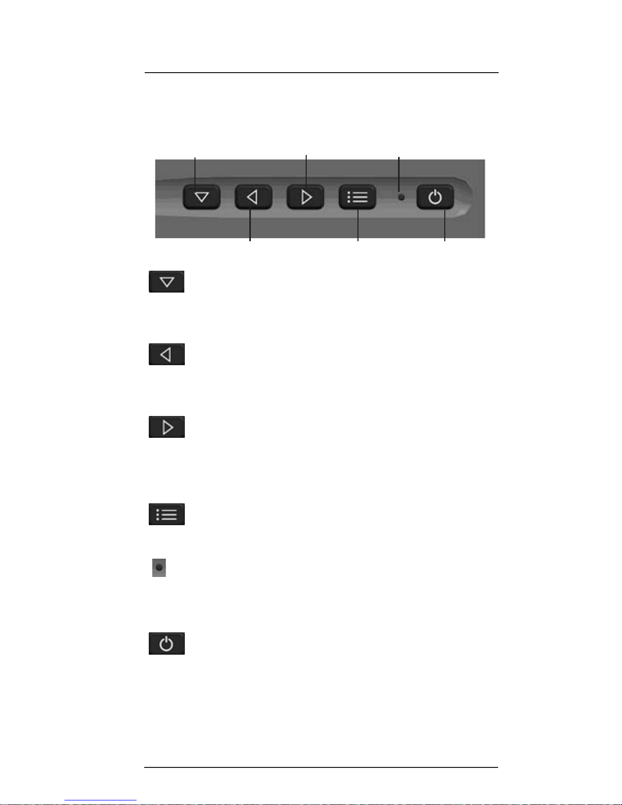
Select Switch/
Menu Scroll
Decrease Value
Sub-Menu Scroll/
Increase Value
OSDON/OFF Power ON/OFF
Status LED
Select Switch/Menu Scroll: Press this button to
switch between video source options , or to scroll
downwhenviewing OnScreenDisplay (OSD)menu
options.
Decrease Value: Press this button during normal
operation to decrease backlight intensity. When
using the OSD, press this button to decrease an
OSDmenu’srange value.
Sub-Menu Scroll/Increase Value: Press this
buttonduring normaloperation toincreasebacklight
intensity. When using the OSD, press this button to
scroll to an OSD sub-menu when available, or use it
toincrease anOSD menu’srangevalue.
OSD ON/OFF: Press this button to display the OSD
Mainmenu. Pressingthe buttonagain willremove
the OSD menu from the screen.
Status LED:The Status LEDshows redwhen the
display is in standby mode, green when the display
is active, and amber when the Select Switch is
pressed.
Power ON/OFF: Press this button to turn the
display ON or OFF.
6.5" Display Button Functions
Displaybuttons areshownand definedbelow.
Operation

Page10 Rosen Aviation Displays
OSD Time-Out Use display buttons to adjust the
range of time that elapses before a
menu will time-out
Power Up Use display buttons to select
Auto-on,Auto-off, or Restore.
Choose Auto-on to have the display
turn ON when power is applied.
Choose Auto-off to have the display
go into Standby mode when power is
supplied. Choose Restore to have the
display return to its last power-ON
status if power is interrupted
RGBAuto Detect This Option is not available with this
Display
Restore Defaults Select this option to restore factory
default settings
Video Formats Scroll to this selection’s sub-menu to
view video format options (shown on
the next page)
Advanced Menu
Options Description
Operation
On Screen Display (OSD) Main Menu
TheOn ScreenDisplay (OSD)provides aset ofmenus that
enableusers toadjust orview screensetup features.Some
Main menu selections lead to submenus with additional setup
options. Press the OSD ON/OFF button to view the Main
menu.Main menuoptions aredescribed below,and then
availablesub-menus arelisted inthe tablesthatfollow.
Main Menu Options Description
Brightness
Contrast
Color
Tint
Sharpness
Backlight Dimming
Advanced Menu Use display buttons to access the
Advanced menu’s sub-menu
Use display buttons to increase or
decrease these options’ range values

6.5” SlimLine LCD Page11
Hours Thisoption displays thehour and
minutes of the display’s life
SWRev This option displays the current
softwarerevision
PowerCycles This optiondisplays thenumber of
times power has been cycled
Source This option displays the current
selectedvideostandard (NTSC/PAL/
SECAM)
Select Switch Adjust RelayActive Time to set the
time delay when pressing the Select
Switchto changevideo sources
Adjust Repeat Delay to set the time
delaywhen pressingandholding the
Select Switch to change video
sources
MonitorInfo Scroll to this selection’s sub-menu to
viewmonitorinformation(seebelow)
Back Select this option to return to the
Advancedmenu
Operation
Advanced Menu
Options Description
Video Formats
Sub-Menu Options Description
Use display buttons to select
betweenthe two choicesof auto
detection.The Displaywill
automatically detect and switch to
theinputvideo standard*
Back Select this option to return to the
Advancedmenu
Monitor Info
Sub-Menu Options Description
NTSC/PAL/SECAM
or
NTSC/PALOnly
continued...
*If the image is black and white when switching from SECAM
to PALvideo standard, press the Select switch

Page12 Rosen Aviation Displays
CurrentTemperature This option displays the most recent
temperaturereadingwithin the
display.Temperaturereadingsupdate
approximatelyevery30seconds
AvgTemp Thisoptiondisplays theaverage of
approximately the last eight current
temperatures
MaxTemp This option displays the highest
temperatureeverrecordedwithin the
display
MinTemp This option displays the lowest
temperatureeverrecordedwithin the
display
OverTemp Thisoption displaysthe numberof
over-temperatureshutdownsthat
haveoccurred.
*Asafety featureshuts downthe
monitor if it reaches or exceeds 140
degreesFahrenheit
Operation
Temperature
Sub-Menu Options Description
TemperatureMenu Scroll to this selection’s sub-menu to
viewmonitortemperatureinformation
(shownbelow)
SignalLevel This optionwill showLow,Good, or
High. If the signal shows Low or
High, adjust the video level at the
source
Back Select this option to return to the
Advancedmenu
Monitor Info
Sub-Menu Options
Continued... Description
continued...

6.5” SlimLine LCD Page13
UnderTemp Thisoption displaysthe numberof
under-temperatureshutdowns that
haveoccurred.
*Asafety featureshuts downthe
monitorif itreachesor dropsbelow
32degreesFahrenheit
Back Select this option to return to the
MonitorInfosub-menu
*Ifan OverTempor UnderTemp shutdownoccurs,
Temp Shutdownisshown onthe OSDfor approximately30
seconds, and then the display shuts off until the temperature
reachesacceptable temperaturelimits. Thedisplay will
then automatically turn back on.
Temperature
Sub-Menu Options
Continued... Description
Operation

Page14 Rosen Aviation Displays
Technician Mode
Technician mode provides the ability to customize and restrict
access to the Main menu for specified options. This section
describes how to enter, enable and disable options, and exit
Technicianmode.
Entering Technician Mode
Completethefollowing listto enterTechnicianmode:
1Apply 28V to the display and wait until the
status LED turns green (if the display is in
auto-off,press thepower ON/OFFbutton).
2Once the status LED turns green, press the
power button to turn it off.
3Pressandhold thepower button downfor 10
secondsbefore releasing it(more than10
seconds is OK).
4Press the OSD ON/OFF button and confirm that
the word On or Off is shown to the left of each
menu option in the Main menu. This verifies that
the display is in Technician mode.
Mainmenu options whenstartingTechnician mode:
On Brightness
On Contrast
On Color
On Tint
On Sharpness
On Backlight
Off Advanced >>
Enabling/Disabling Individual Menu Items
Usethe display buttonsper normal operationto navigate
through menu options.Adjust the menu options as desired
and then enable or disable the option for users as desired.
Disable a menu option as follows:
1Highlightthe desired menuoption.
2Press and hold the Select switch in for 5
seconds.
3Release the Select switch; the next option
becomeshighlighted andthe word OFFappears
next to the disabled menu option.
Technician Mode

6.5” SlimLine LCD Page15
Enabling/Disabling Individual Menu Items
Continued...
Enable a menu option as follows:
1Highlightthe desired menuoption.
2Press and hold the Select switch in for 5
seconds.
3Release the Select switch; the next option
becomeshighlighted andthe wordON appears
next to the enabled menu option.
When the monitor is returned to normal mode, any items
which were disabled in technician mode will no longer be
available in the main menu. It is possible to disable all Main
menu items; in this case there will be no user accessible
functions in the Main menu.
Note: theIncreaseand DecreaseValue buttonswill not work
to adjust menu options disabled inTechnician mode.
Below is an example of how adjustments inTechnician mode
affecttheappearance andoptions within thenormal Main
menu.
Technician Mode
Main Menu:
On Brightness
On Contrast
On Color
OffTint
Off Sharpness
Off Backlight
OffAdvanced
Normal Mode
Main Menu Options:
Brightness
Contrast
Color
Exiting Technician Mode
To exit the Technician mode, simply turn the power off and
on again either with the power button or through the 28V
supply.
Technician Mode

Page16 Rosen Aviation Displays
Troubleshooting
Troubleshooting
Ifthe monitordoes notfunction properly, referto thefollowing
troubleshootingtable forsymptoms andpossible solutions
beforecontacting Rosenfield support.
Notes:
•Always use an oscilloscope to verify the video signal
•Alwaysuse amultimeter toverify voltages
•Checkactual results againstthe requirements
describedin this manual
PROBLEM POSSIBLE SOLUTION
Nopower Verify that the pinout is correct . Push
andhold thepower switchfor aboutone
second.
Verify Monitor is fully inserted into base
receptacle.
Novideoon Verify that the pinout is correct.
screen Verify that the video source is on and has
a tape or DVD installed.
Verifyvideo signalat monitorend, Usean
oscilloscopeor anothermonitor.
Screen is Verify that the monitor is getting power
(green LED on) and the pinout is correct.
Verify that the video source is on and has
a tape or DVD installed.
Verifyall connections
Screen is blue Verify signal at monitor end, Use an
oscilloscopeor anothermonitor.
Verify that the pinout is correct.
Verify that the video source is on and has
a tape or DVD installed.
black

6.5” SlimLine LCD Page17
Troubleshooting
Red LED is on Monitor is connected to 28 volts but is
either switched off or is not receiving a
videosignal(Standbymode)
Anover temporunder tempoccurred
(seepages11 and12)
Imageis distorted Verify that the pinout is correct.
Usethe OSDMonitor Infosub-menu to
verify that a signal is present and not too
highor low(see page11)
Examinesystem forpinched ordamaged
cables
Image is black
andwhitewhen
switching
betweenSECAM
andPAL
PROBLEM POSSIBLE SOLUTION
Technical Support
Forfield support orto orderparts,contactRosenAviation
Displaysat: 1-888-668-4955
orvisit usat: www.rosenaviation.com
If the image is black and white when
switching from SECAM to PALvideo
standard, press the Select switch

Page18 Rosen Aviation Displays
Specifications
Specifications
LCDPerformance
ScreenResolution (pixels) 640 w x 480 h
DisplayViewingArea 5.14 x 3.84 in
ViewingAngle (At contrast ratio 10:1 )
Horizontal ±50º
Vertical +35º up -45º down
ContrastRatio 300:1(Typical)
BacklightLamp Life 30000 hours continuous
operation
ScreenBrightness 400 cd/m2 (Typical)
MechanicalPackaging
Arm Mount Weight (SeeAppropriateDrawing)
PowerRequirements 28VDC 350mANominal
VideoPerformance
VideoStandards NTSC, PAL, SECAM,
RS-170(B&W)
Video input 1V Peak-to-Peak, 75 Ohms
OperatingTemperature 0ºC - 50ºC FreeAir Installation
0ºC - 40ºC Insulated Installation
Warranty 2 year
DO-160DTesting
This Display is compliant with and has been tested to
applicableDO-160Dstandards. Forspecificinformation
contacta RosenCustomerService Representativeat
1.888.668.4955.

6.5” SlimLine LCD Page19
Disclaimer
Disclaimer
All information, including illustrations, is believed to be reliable. Users and/
or installers, however, should independently evaluate the suitability of
each product for their application. Rosen makes no warranties as to the
accuracy or completeness of the information, and disclaims any liability
regarding its use or installation. Rosen’s only obligations are those in the
Rosen Standard Terms and Conditions of Sales for this product, and in no
case will Rosen be liable for any incidental, indirect or consequential
damages arising from the sale, resale, use or misuse of the product.
Specifications are subject to change without notice. Rosen reserves the
right to make changes - without notification to buyer - to materials or
processing that do not affect compliance with any applicable
specifications.
Table of contents
Other Rosen Monitor manuals