Rosko JULIEN RO-FFG-115-N User manual

1RO_FFG_GUIDE (08/22)
INSTALLATION GUIDE
Operation, Maintenance, and Service Parts
RO-FFG-115-N RO-FFG-160-N
RO-FFG-115-P RO-FFG-160-P
EN
Gas Floor Fryer
RO-FFG
RO-FFG-115
RO_FFG_GUIDE (08/22)
955, rue Lachance
Québec, QC G1P 2H3
Canada
1-866-901-5624
www.rosko-julien.ca
991002623

2RO_FFG_GUIDE (08/22)
1. WARNINGS AND CAUTIONS
To qualify for our warranty, you must exclusively dedicate this device to commercial use and ensure that
the installation is executed by a certified technician. In the event of non-compliance with one of these conditions,
the warranty will be considered expired. You will be asked for proof in the event of a claim.
WARNING
Any installation, adjustment, modification, repair, or maintenance not in accordance with applicable standards may
cause property damage, injury, or death. To ensure a safe installation and proper operation of your Rosko equipment,
please read this entire guide and keep it for future reference.
•This unit is intended for commercial use only.
•Installation must meet the requirements of the codes below, where applicable:
◽State codes or local codes, or in the absence of local codes:
◽In the United States, national gas code ANSI Z223.1 / NFPA 54;
◽In Canada, installation code for natural gas CSA B149.1 or propane gas CSA B149.2;
◽In Canada, the electrical code CSA C22.1.
•Installation of this unit must be done by a qualified person, where required by law.
•Do not store fuels or other flammable materials near the unit.
•Never heat the fry tank when it is empty. This will burn the tank, cause a crack, and void the warranty.
•If a gas odour is detected, shut off the gas supply at the main valve and then contact the local gas supplier for service.
WARNING
Keep a copy of these instructions in a visible location1.
1
This guide is updated as new information or new products become available.
Visit our website rosko-julien.ca for the most recent version of these documents.

3RO_FFG_GUIDE (08/22)
CONTENTS
1. WARNINGS AND CAUTIONS . . . . . . . . . . . . . . . . . . . . . . . . . . . . . . . . . . . . . . . . . . . . . . . . . . . . . . . . . . . . . . . . . . . . . . . . . . . . . . . . . . . . . . . . . . . . . . 2
2. PLANNING AND INSTALLATION . . . . . . . . . . . . . . . . . . . . . . . . . . . . . . . . . . . . . . . . . . . . . . . . . . . . . . . . . . . . . . . . . . . . . . . . . . . . . . . . . . . . . . . . . . . 4
2.1. CLEARANCES ........................................................................................................ 4
2.2. AIR SUPPLY AND VENTILATION ....................................................................................... 4
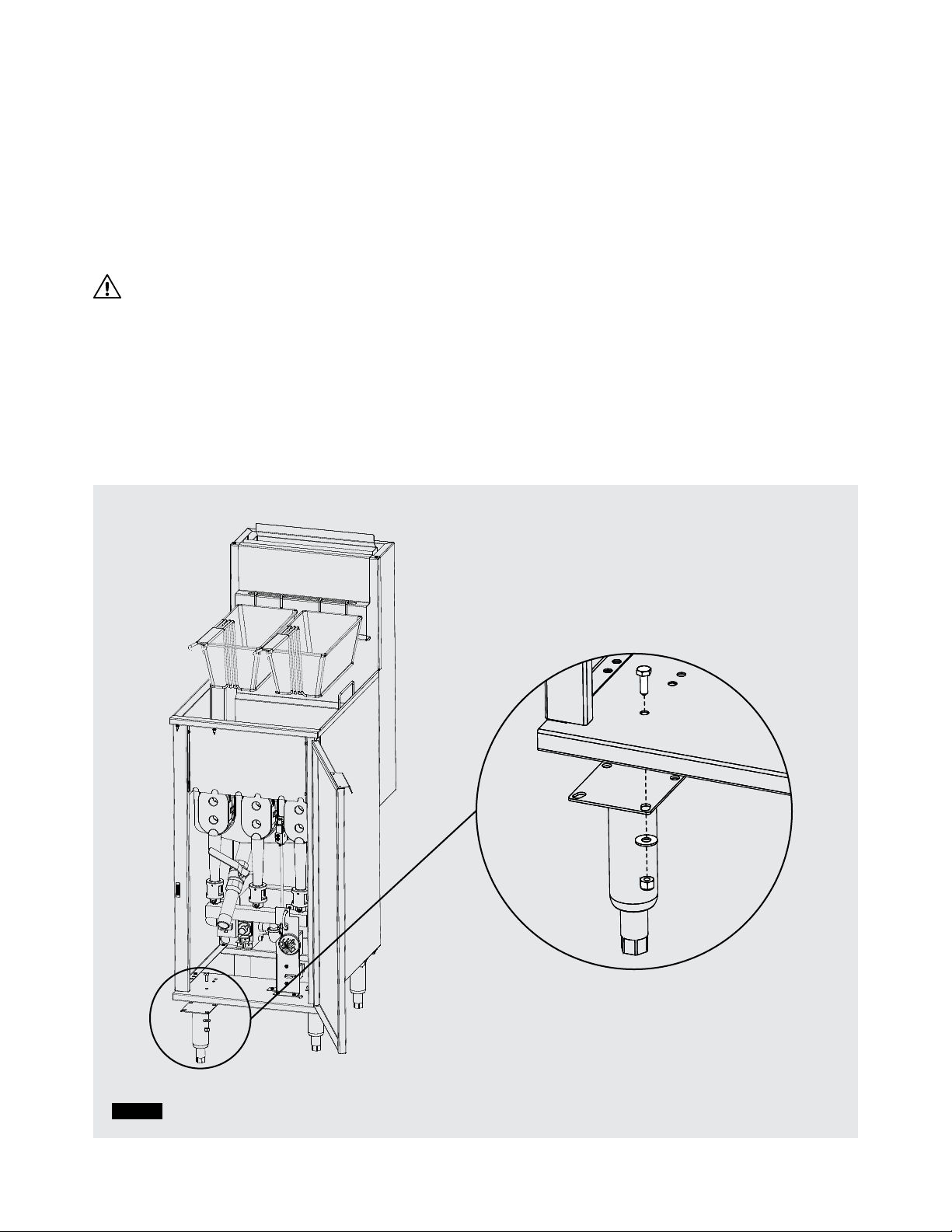
2.3. LEG INSTALLATION ................................................................................................... 6
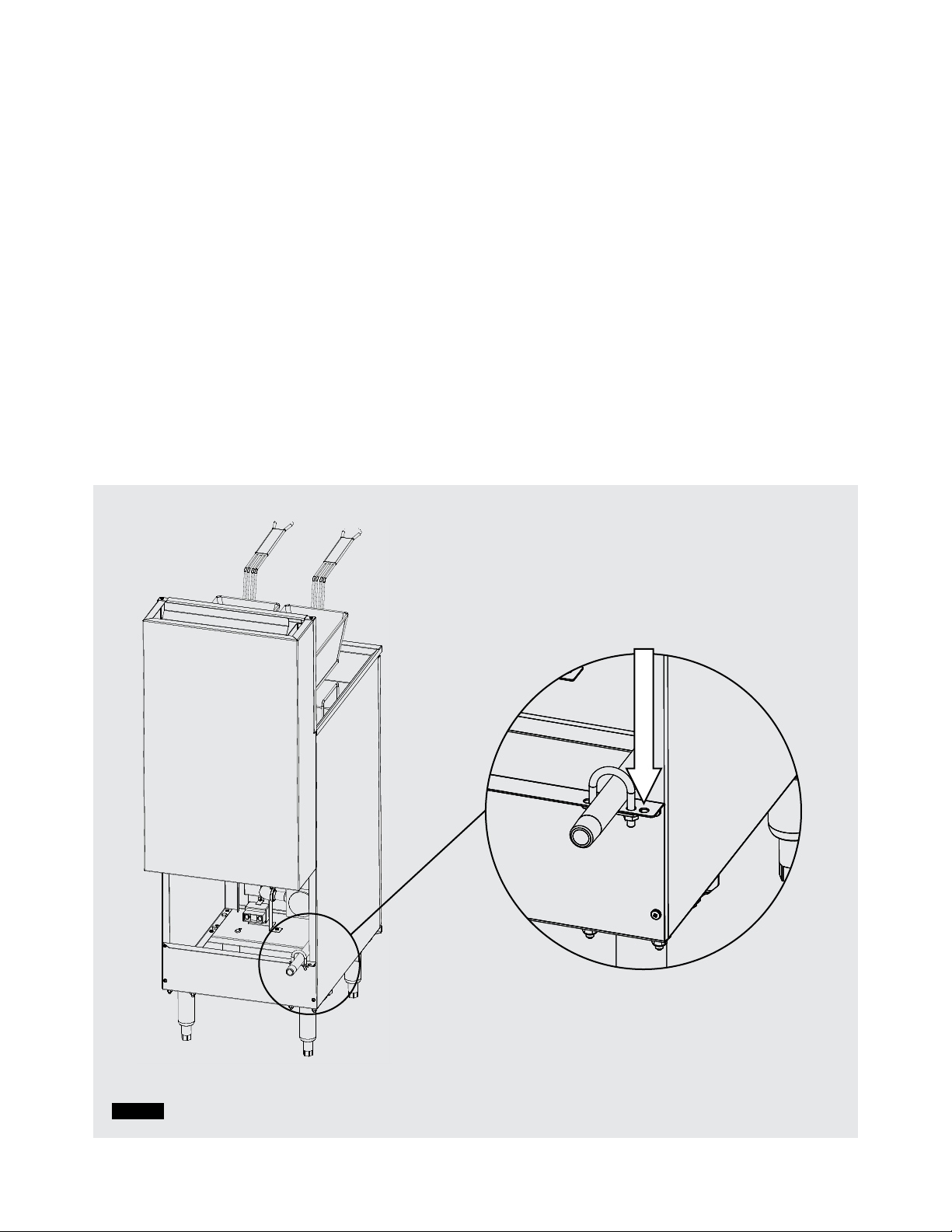
2.4. ATTACHMENT ........................................................................................................ 7
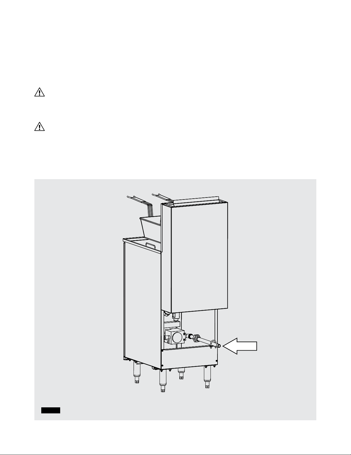
2.5. CONNECTION ........................................................................................................ 8
2.6. GAS PRESSURE CHECK .............................................................................................. 9
3. OPERATION . . . . . . . . . . . . . . . . . . . . . . . . . . . . . . . . . . . . . . . . . . . . . . . . . . . . . . . . . . . . . . . . . . . . . . . . . . . . . . . . . . . . . . . . . . . . . . . . . . . . . . . . . . . . . 10
3.1. FILLING .............................................................................................................. 10
3.2. IGNITION ............................................................................................................ 11
3.3. CLOSING ............................................................................................................ 12
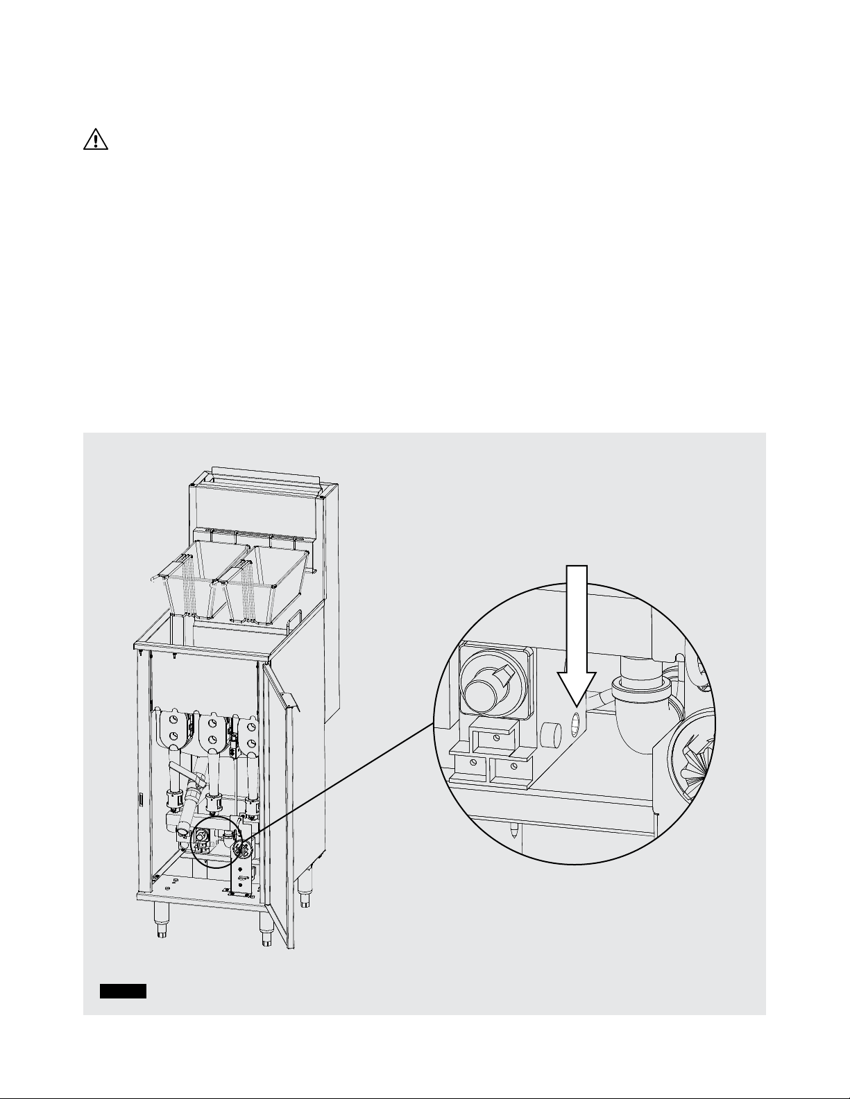
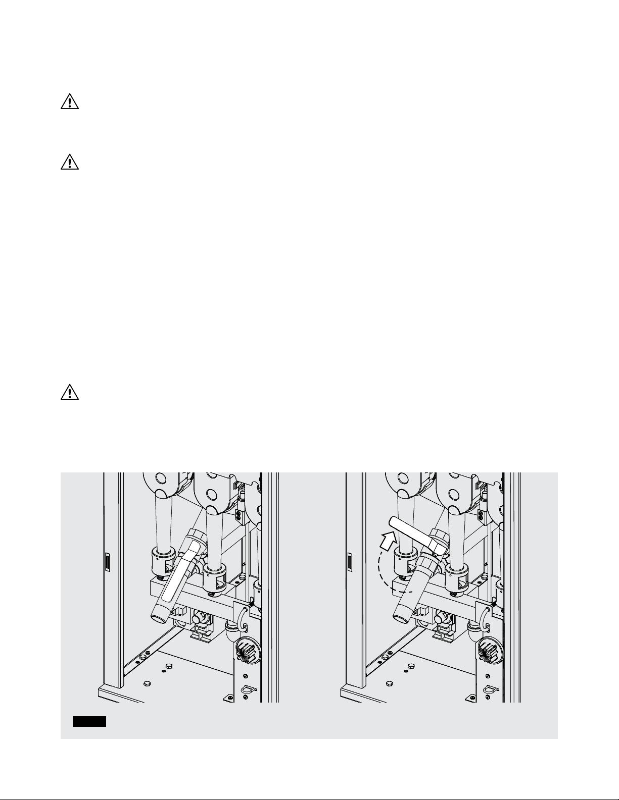
3.4. DRAINAGE ........................................................................................................... 12
4. CLEANING . . . . . . . . . . . . . . . . . . . . . . . . . . . . . . . . . . . . . . . . . . . . . . . . . . . . . . . . . . . . . . . . . . . . . . . . . . . . . . . . . . . . . . . . . . . . . . . . . . . . . . . . . . . . . . . 13
4.1. SURFACE CLEANING................................................................................................. 13
4.2. ACCESSORY CLEANING ............................................................................................. 13
4.3. FILTRATION .......................................................................................................... 13
4.4. TANK CLEANING ..................................................................................................... 14
5. PREVENTIVE MAINTENANCE . . . . . . . . . . . . . . . . . . . . . . . . . . . . . . . . . . . . . . . . . . . . . . . . . . . . . . . . . . . . . . . . . . . . . . . . . . . . . . . . . . . . . . . . . . . 15
5.1. MINIMUM INSPECTION .............................................................................................. 15
5.2. PROFESSIONAL INSPECTION ....................................................................................... 15
6. TROUBLESHOOTING . . . . . . . . . . . . . . . . . . . . . . . . . . . . . . . . . . . . . . . . . . . . . . . . . . . . . . . . . . . . . . . . . . . . . . . . . . . . . . . . . . . . . . . . . . . . . . . . . . . . . 16
6.1. GENERAL TROUBLESHOOTING ..................................................................................... 16
6.2. TROUBLESHOOTING CHART ........................................................................................ 17
7. SERVICE PARTS . . . . . . . . . . . . . . . . . . . . . . . . . . . . . . . . . . . . . . . . . . . . . . . . . . . . . . . . . . . . . . . . . . . . . . . . . . . . . . . . . . . . . . . . . . . . . . . . . . . . . . . . . . 18
7.1. RO-FFG-115-N and RO-FFG-115-P .................................................................................. 18
7.2. RO-FFG-160-N and RO-FFG-160-P ................................................................................. 20
8. SPECIFICATIONS . . . . . . . . . . . . . . . . . . . . . . . . . . . . . . . . . . . . . . . . . . . . . . . . . . . . . . . . . . . . . . . . . . . . . . . . . . . . . . . . . . . . . . . . . . . . . . . . . . . . . . . . 22
9. ELECTRICAL DIAGRAM . . . . . . . . . . . . . . . . . . . . . . . . . . . . . . . . . . . . . . . . . . . . . . . . . . . . . . . . . . . . . . . . . . . . . . . . . . . . . . . . . . . . . . . . . . . . . . . . . 23
CONTACT US . . . . . . . . . . . . . . . . . . . . . . . . . . . . . . . . . . . . . . . . . . . . . . . . . . . . . . . . . . . . . . . . . . . . . . . . . . . . . . . . . . . . . . . . . . . . . . . . . . . . . . . . . . . . . . . 24

4RO_FFG_GUIDE (08/22)
2.PLANNING AND INSTALLATION
Congratulations on purchasing your new Rosko gas floor fryer!
To maximize the use and durability of your unit, we recommend that you follow the instructions in this manual.
Installation, operation, and maintenance procedures must be followed for warranty protection to apply.
2.1. CLEARANCES
When planning and installing the unit, it is important to respect the following minimum distances with regards
to clearance:
•Construction with combustible materials
◽6" (152 mm) at the back of the unit
◽3" (76 mm) on each side of the unit
•Construction with non-combustible materials
◽0 '' (0 mm) at the back and on each side of the unit
•Provide adequate space for the operation and maintenance of the unit
2.2. AIR SUPPLY AND VENTILATION
Provide adequate ventilation above the unit. You must always place the fryer under a ventilation hood to evacuate
burnt gas fumes outside the building.
Never obstruct the chimney located at the back of the unit as it allows to evacuate the gases burnt
during operation.
WARNING
Installation of this appliance must comply with the requirements of the standard for venting fumes of cooking
equipments ANSI-NFPA 96 (latest edition).

5RO_FFG_GUIDE (08/22)
RECEPTION AND INSPECTION
This unit has been inspected and verified before shipment. Upon receipt, immediately check for damage
in the presence of the delivery person. If necessary, issue a claim immediately.
The warranty is limited to the replacement of defective parts under normal use. No claim will be accepted
for damage resulting from improper installation, inadequate operation, or unauthorized service prior to installation.
Before installation, make sure the gas floor fryer specifications match the type of gas supply. Refer to the nameplate
on the inside of the door.
Important: Confirm that you have received all the parts included with your fryer model.
All Gas Floor Fryer models
Material included:
•1 deep fryer
•4 adjustable legs
•16 hex nuts ⁄ - 20
•16 bolts ⁄ - 20
•16 flat washers ⁄
•1 drain pipe 1" x 5''
•2 baskets
•1 screen
•1 instruction guide

6RO_FFG_GUIDE (08/22)
Figure 1
2.3. LEG INSTALLATION
Tilt the fryer to gain access to the bottom of the unit. Using a 7/16" hex wrench, secure the legs to the base
of the fryer with the included 4 hex bolts. (Figure 1) Adjust the legs so that the fryer is level when in position.
NOTE: To avoid the risk of injury, two people are required to handle the unit.
For a moveable installation on casters, purchase the RO-ACC-FFG-4W 4-caster set (sold separately).
Caster installation instructions are included with the kit.
WARNING
In the case of a moveable installation on casters, the installation must meet the requirements of the standards below,
where applicable:
•In the United States, Standards for Connectors for Moveable Gas Appliances ANSI Z21.69
and Standards for Quick Disconnect Devices ANSI Z21.41
•In Canada, Standards for Connectors for Moveable Gas Appliances CSA 6.16
and Standard for Quick Disconnect Devices CSA 6.9
Figure 1

7RO_FFG_GUIDE (08/22)
Figure 2
2.4. ATTACHMENT
Do not use the connector or the gas supply hose to restrict fryer movement. Attachment can be done by inserting
the fryer into a battery of appliances or by securing the fryer to the back wall using a chain that is shorter than
the gas supply pipe and a ring. (Figure 2).
NOTE: Attachment material is not included.
ATTACHMENT

8RO_FFG_GUIDE (08/22)
2.5. CONNECTION
The 1/2" NPT gas connector is located at the back of the fryer. (Figure 3)
The connection must be made by a licensed technician.
When connecting the gas supply to the unit’s connector, use a second wrench to tighten to prevent
any movement of the internal piping.
WARNING
After connection and before ignition, open the gas supply valve and check the joints for any leaks with soapy water.
Never use a flame to check for gas leaks.
WARNING
Installation must meet the requirements of the codes below, where applicable:
•State codes or local codes, or in the absence of local codes:
•In the United States, national gas code ANSI Z223.1 / NFPA 54;
•In Canada, installation code for natural gas CSA B149.1 or propane gas CSA B149.2;
•In Canada, the electrical code CSA C22.1.
Figure 3
1/2'' NPT GAS
CONNECTOR

9RO_FFG_GUIDE (08/22)
2.6. GAS PRESSURE CHECK
WARNING
This unit and the gas valve located behind the door must be disconnected from the gas piping supply connected
to the unit during the system pressure test when testing more than ½ psi (3.45 kPa).
1. To measure gas pressure, use the designated opening on the safety valve. (Figure 4)
Normal pressure should be:
•3.5" W.C. for natural gas
•10" W.C. for propane gas
Make sure the burners are operating at maximum capacity while checking the pressure. Operate all other
equipment connected to the gas piping supply at maximum capacity, then read the pressure.
2. Shut off all other appliances and take a second pressure reading. If the pressure varies by more than 1" W.C.,
install a pressure regulator (not included) between the gas piping supply and the unit. (Figure 3)
3. Then adjust the system to the prescribed pressure.
Figure 4
OPENING OF
THE SAFETY VALVE

10 RO_FFG_GUIDE (08/22)
3. OPERATION
WARNING
Accidents associated with transporting the unit when the tank is filled with liquid can cause damage and serious injury.
To prevent an accident when transporting the unit, always empty the fry tank of its liquid as explained in the DRAINAGE
section of this guide.
WARNING
During use, it is very important not to press the ends of the baskets on the chimney of the fryer to prevent oil from
settling on the chimney walls. Oil build-up on the internal or external chimney walls can cause a fire in the fryer.
3.1. FILLING
Before using the fryer, clean the tank with a stainless steel cleaning product designed for fryer maintenance
so as not to contaminate the oil or grease.
1. Close the ball valve located at the front of the fryer. (Figure 5)
2. Fill the tank with 23 liters of oil or melted fat, until the level is one (1) inch from the rear edge of the tank.
(Figure 6)
For use with solid fat, be sure to follow the next steps to melt the fat:
1. Remove the baskets and the screen from the tank.
2. Cut the fat into slices thin enough to fit between the tubes.
3. Fill the tank with slices of fat.
4. Open the thermostat knob for 20 seconds.
5. Close the thermostat knob for 20 seconds.
6. Repeat the previous 2 instructions until the heating tubes are completely covered with melted fat.
WARNING
A melting cycle is necessary when using solid fat to avoid cracking the tank and voiding the warranty,
due to excess heat on the walls of the heating tubes. Excess heat is caused when the surface of the tubes
is not in contact with oil.
Figure 5 Open drain valve Closed drain valve

11RO_FFG_GUIDE (08/22)
3.2. IGNITION
1. Turn the thermostat knob to the “OFF” position. (Figure 7)
2. Press and turn the gas control knob to the “PILOT” position. (Figure 8)
3. Press and hold the gas control knob while manually lighting the pilot. (Figure 8)
4. Hold the knob down for 45 seconds.
5. If the pilot light does not stay on, repeat the procedure.
6. Place the gas control knob in the “ON” position.
7. Set the thermostat knob to the desired temperature.
Figure 7 Figure 8
Figure 6
— MAX —
OFF
PILOT
ON
ARRÊT-OFF
400
350
300
250
200
— MAX —

12 RO_FFG_GUIDE (08/22)
3.3. CLOSING
1. Turn the thermostat knob to the “OFF” position. (Figure 7)
2. Place the gas control knob in the “OFF” position. (Figure 9)
3. Close the gas supply valve connected to the unit.
3.4. DRAINAGE
1. Wait for the oil or grease to cool before emptying the tank.
2. Attach the 1” drain pipe to the ball valve located behind the door. (Figure 10)
3. Place a container that is large enough to catch all of the used oil under the drain pipe.
4. Open the ball valve and let the used oil or grease drain out.
5. Securely close the ball valve.
OFF
PILOT
ON
Figure 10
Figure 9
DRAIN PIPE
Figure 7
ARRÊT-OFF
400
350
300
250
200

13RO_FFG_GUIDE (08/22)
4.CLEANING
WARNING
The suggested maintenance procedures pose burn hazards to the user and those around them and therefore require
special attention. It is important not to splash cleaning solution or water into the tank when the oil is boiling and thus
avoid contaminating the oil or causing heavy splashing of boiling oil.
4.1. SURFACE CLEANING
Be sure to keep all surfaces of the fryer tank as clean as possible to avoid charring and thus contamination of the oil or
grease. Exposed stainless steel surfaces and exterior parts of the unit should be cleaned each day with a mild soap or a
commercial cleaner designed for this purpose.
WARNING
Check for oil build-up on the inner and outer walls of the chimney. If you find oil build-up on the chimney walls, have the
chimney cleaned by a maintenance service company to avoid a fire hazard.
4.2. ACCESSORY CLEANING
It is important to regularly clean your fryer accessories by hand using a commercial degreaser or with hot water and a
commercial dishwasher.
•The fry tank’s baskets, stand, and screens should be cleaned every day after service.
•Additional accessories such as a drip tray or lid should be cleaned weekly or when you clean the tank according
to the broil out procedure.
4.3. FILTRATION
Remember to change and filter the oil or grease regularly to avoid contaminating food, especially after using the fryer
to fry meat. It is possible to detect the deterioration of the oil by a change in colour, odour or by the presence of foam
when the oil is stirred.
Depending on the frequency of use, it is recommended that the oil be filtered daily. To do so, follow the steps below:
1. Wait for the oil to cool before emptying the tank.
2. Attach the 1" drain pipe to the ball valve behind the door. (Figure 10)
3. Place a large enough filter (not included) under the drain pipe.
4. Open the ball valve and let the used oil or grease drain.
5. Close the ball valve tightly.
6. Clean the bowl according to section 4.3. of the guide.
7. Fill the bowl with filtered oil up to the rear edge of the tank. (Figure 6)

14 RO_FFG_GUIDE (08/22)
4.4. TANK CLEANING
Boil out is a deep cleaning process that increases the durability and efficiency of your deep fryer cooking tank.
Proper maintenance will help prevent grime from forming while maintaining optimal cooking and food taste.
It is strongly recommended to perform the scald procedure at least once (1) a week. To do so, follow the steps below:
1. Drain the oil from the fryer according to section 3.4. of the guide and leave the drain valve open.
2. Use a cleaning rod to clear the drain hole.
3. Rinse off excess grease with hot water.
4. Close the drain valve and add water to the back edge of the tank.
5. Add a quantity of fryer tank cleaner.
6. Gently bring the water to a boil for twenty (20) minutes.
7. Turn off the unit and open the drain valve to let the water evacuate.
8. Clean the fronts and tubes of the bowl with a fryer brush (not included).
9. Rinse with water to remove the remaining residue.
10. Check the condition of the temperature bulb.
11. Close the drain valve and refill the bowl with oil.
WARNING
Make sure that the water is completely removed and that the tank has time to dry before filling it with oil.

15RO_FFG_GUIDE (08/22)
5. PREVENTIVE MAINTENANCE
WARNING
Any inspection or maintenance performed while the fryer is in operation must be done with care to avoid the risk
of burns, and when possible, with the unit and power supply completely shut off.
5.1. MINIMUM INSPECTION
This section is dedicated to the unit user
Preventive maintenance procedures that are intended for the fryer user are mostly listed threw the cleaning
procedures. However, even though you reduce the risk of complications with proper cleaning, some preventive
inspections are recommended for you.
•Check the condition of the temperature bulb in the fry tank when draining or filtering oil from the fryer.
•Inspect for charred spots around the chimney and fry tank.
•Inspect the condition of the unit’s internal components for wear or displacement.
WARNING
Heavy use and improper gas pressure can cause carbon dust to build up in the heat pipes. This effect can, in
particular, take the form of poor quality yellow flames or the appearance of soot coming out of the chimney.
To avoid complications and ensure proper operation of the unit, please contact a service company once (1) a year to
apply :
- Cleaning of the heat pipes.
- Cleaning of the burner orifices.
- Verification of the gas operating pressure.
5.2. PROFESSIONAL INSPECTION
This section is dedicated to authorized technicians only
Periodic maintenance and preventive inspections by a certified technician are strongly recommended to avoid
equipment failure in unexpected situations. Contact a service company to determine an annual inspection schedule
that will meet your needs.
These inspections include replacement or repair of parts, but they may also offer other types of support, as
summarized below:
•Inspecting the inside of the unit and detecting oil leaks.
•Inspecting the chimney for oil or particle build-up.
•Evaluating gas control operation.
•Calibrating the thermostat.
•Measuring the gas pressure of the appliance. (Section 2.7.)
•Detecting gas leaks.
•Cleaning the gas injectors.
•Inspecting the burner ports, heat tubes, and flame deflectors.

16 RO_FFG_GUIDE (08/22)
6. TROUBLESHOOTING
6.1. GENERAL TROUBLESHOOTING
This section is dedicated to the unit user
When a operating problem occurs with the unit, it may be resolved using the general troubleshooting checks listed
below. However, if the problem persists, or if you feel that the problem may present a hazard, contact an authorized
service technician immediately.
•Make sure your gas supply type respects the requirements of the name plate located behind the door of the unit.
•Look that the gas supply valve to the fryer is open.
•Look that the gas control knob is in the correct position for the ignition procedures.
•Make sure the pilot flame is lit when turning the thermostat.
•Look that the thermopile is straight and at a distance of 5 mm from the pilot.
6.2. TROUBLESHOOTING CHART
This section is dedicated to authorized technicians only
WARNING
Only qualified service personnel should use the troubleshooting chart to repair this fryer. Many operations require
knowledge of the unit and precautions to be taken with the gas supply to avoid serious injury.
The problems and possible solutions listed in the troubleshooting chart below are typical problems frequently
encountered. For any part replacement, we invite you to consult section 7 of the guide to find the associated
item number and the technical drawing of the unit.
The warrant will be considered expired and Rosko will not be charged responsible if :
1. A maintenance, a reparation or a part replacement is done by a non authorized technician.
2. Some parts not approved by Rosko are replaced in the appliance.

17RO_FFG_GUIDE (08/22)
NOTE: Be sure to have this chart in hand for any troubleshooting questions that may be directed to Rosko
Customer Service.
Problem Possible cause Possible solution
The pilot does not
light up.
1. The appliance is not compatible
with your type of power input.
2. The main gas supply is closed.
3. The devis gas pressure is not adjusted.
4. The pilot light is defective.
5. The multifunction gas control
is defective.
1. Ensure that your gas supply complies with
the devis nameplate.
2. Ensure the main supply valve is open.
3. Check and adjust the gas pressure according
to section 2.7.
4. Change the pilot light according to section 7.
5. Change the gas control according to section 7.
The pilot lights up
but goes out when
the gas control
knob is released.
1. The pilot orifice is clogged.
2. Suspended connection between
the gas control and the high limit.
3. Suspended connection between
the thermopile and the high limit.
4. The high limit protection devise
is defective.
5. The thermopile is defective.
1. Remove the pilot light and clean its orifice hole.
2. Check the condition of the wires and the
connectors between those components.
3. Check the condition of the wires and
the connectors between those components.
4. Ensure that the high limit contact is closed
or change it according to section 7.
5. Change the thermopile according to section 7.
The burners do not
light when the
thermostat is
turned on.
1. The gas control knob is not positioned
correctly.
2. The devis gas pressure is not adjusted.
3. The thermostat is defective.
4. The gas control devise is defective.
1. Ensure that the gas control is positioned to ‘’ON’’.
2. Check and adjust the gas pressure according
to section 2.7.
3. Change the thermostat according to section 7.
4. Change the gas control according to section 7.
Lack of heat when
operating
the appliance.
1. The gas pressure is too low.
2. The thermostat is not properly
adjusted.
3. The burners do not transmit heat
properly to the tank.
4. The thermostat is defective.
1. Check and adjust the gas pressure, then adjust
the regulator if necessary.
2. Check the temperature with an external
thermometer and adjust the devis thermostat.
3. Remove the burners to check all gas injectors
and check the condition of the flame deflectors.
4. Change the thermostat according to section 7.
The oil overheats
during the use and
the fryer does not
stop by itself.
1. A temperature bulb is defective.
2. The thermostat is defective.
3. The gas control is defective.
1. Remove the oil and check the condition
of the temperature bulbs in the tank
2. Adjust or change the thermostat according
to section 7.
3. Change the gas control according to section 7.

18 RO_FFG_GUIDE (08/22)
7. SERVICE PARTS
7.1. RO-FFG-115-N and RO-FFG-115-P
See figure 11 for identification of service parts
# Code Description Qty
1 202120003 Fry Tank for RO-FFG-115 1
2 930600141 1" Ball Valve 1
3 932150083 1" x 5" Drain Pipe 1
4
935150057 Natural Gas Pilot Light with Thermopile 1
935150058 Propane Gas Pilot Light with Thermopile 1
5 935900036 Flexible 1/4" x 18" SS Gas Tubbing 1
6 940450015 Magnetic Door Latch 1
7
935900035 Propane Gas Injector Hex 1/2" #51 3
935900037 Natural Gas Injector Hex 1/2" #34 3
8
935150056 Propane Gas Multifunction Gas Control 1
935150055 Natural Gas Multifunction Gas Control 1
9 913200021 Thermostat OFF/200-400 °F, 36" Capillary Tube 1
10 913900222 High Limit Safety Switch 460 °F 1
11 913900220 Control Knob for Commutable Ring 1
12 913900221 Knob Ring for Control OFF/200-400 °F 1
13 935350024 Cast Iron Burner for Gas Fryer, Left Slot 1
14 935350023 Cast Iron Burner for Gas Fryer, Right Slot 1
15 935350022 Cast Iron Burner for Gas Fryer 1
16 202120008 Flame Deflector for Gas Fryer 3

19RO_FFG_GUIDE (08/22)
4
15
14
13
2
3
5
6
7
8
11
12
9
10
1
16
Figure 11

20 RO_FFG_GUIDE (08/22)
7.2. RO-FFG-160-N et RO-FFG-160-P
See figure 12 for identification of service parts
# Code Description Qty
1 202101057 Fry Tank for RO-FFG-160 1
2 930600141 1" Ball Valve 1
3 932150083 1" x 5" Drain Pipe 1
4
935150057 Natural Gas Pilot Light with Thermopile 1
935150058 Propane Gas Pilot Light with Thermopile 1
5 935900036 Flexible 1/4" x 18" SS Gas Tubbing 1
6 940450015 Magnetic Door Latch 1
7
935900035 Propane Gas Injector Hex 1/2" #51 4
935900037 Natural Gas Injector Hex 1/2" #34 4
8
935150056 Propane Gas Multifunction Gas Control 1
935150055 Natural Gas Multifunction Gas Control 1
9 913200021 Thermostat OFF/200-400 °F, 36" Capillary Tube 1
10 913900222 High Limit Safety Switch 460 °F 1
11 913900220 Control Knob for Commutable Ring 1
12 913900221 Knob Ring for Control OFF/200-400 °F 1
13 935350024 Cast Iron Burner for Gas Fryer, Left Slot 2
14 935350023 Cast Iron Burner for Gas Fryer, Right Slot 2
15 202120008 Flame Deflector for Gas Fryer 4
This manual suits for next models
3
Table of contents
Other Rosko Commercial Food Equipment manuals