Ross CMA-8011A User manual

Ross Video Limited
CMA-8011A
Component Monitoring
Amplifier
User Manual
Ross Part Number: 8011ADR-004
Issue: 05

CMA-8011A •Component Monitoring Amplifier User Manual
• Ross Part Number: 8011ADR-004
• Document Issue: 05
• Release Date: November 22, 2005. Printed in Canada.
The information contained in this User Manual is subject to change without notice or obligation.
Copyright
© 2005 Ross Video Limited. All rights reserved.
Contents of this publication may not be reproduced in any form without the written permission of Ross
Video Limited. Reproduction or reverse engineering of copyrighted software is prohibited.
Notice
The material in this manual is furnished for informational use only. It is subject to change without
notice and should not be construed as a commitment by Ross Video Limited. Ross Video Limited
assumes no responsibility or liability for errors or inaccuracies that may appear in this manual.
Trademarks
•is a registered trademark of Ross Video Limited.
•Ross, ROSS, ROSS, and MLE are registered trademarks of Ross Video Limited.
•All other product names and any registered and unregistered trademarks mentioned in
this manual are used for identification purposes only and remain the exclusive property
of their respective owners.

Important Regulatory and Safety Notices
Before using this product and any associated equipment, refer to the “Important Safety Instructions”
listed below so as to avoid personnel injury and to prevent product damage.
Products may require specific equipment, and /or installation procedures be carried out to satisfy
certain regulatory compliance requirements. Notices have been included in this publication to call
attention to these Specific requirements.
Symbol Meanings
This symbol on the equipment refers you to important operating and maintenance
(servicing) instructions within the Product Manual Documentation. Failure to heed
this information may present a major risk of damage or injury to persons or
equipment.
Warning
The symbol with the word “Warning” within the equipment manual indicates a
potentially hazardous situation, which if not avoided, could result in death or serious
injury.
Caution
The symbol with the word “Caution” within the equipment manual indicates a
potentially hazardous situation, which if not avoided, may result in minor or
moderate injury. It may also be used to alert against unsafe practices.
Notice
The symbol with the word “Notice” within the equipment manual indicates a
situation, which if not avoided, may result in major or minor equipment damage or a
situation which could place the equipment in a non-compliant operating state.
ESD
Susceptibility
This symbol is used to alert the user that an electrical or electronic device or
assembly is susceptible to damage from an ESD event.
Important Safety Instructions
Caution
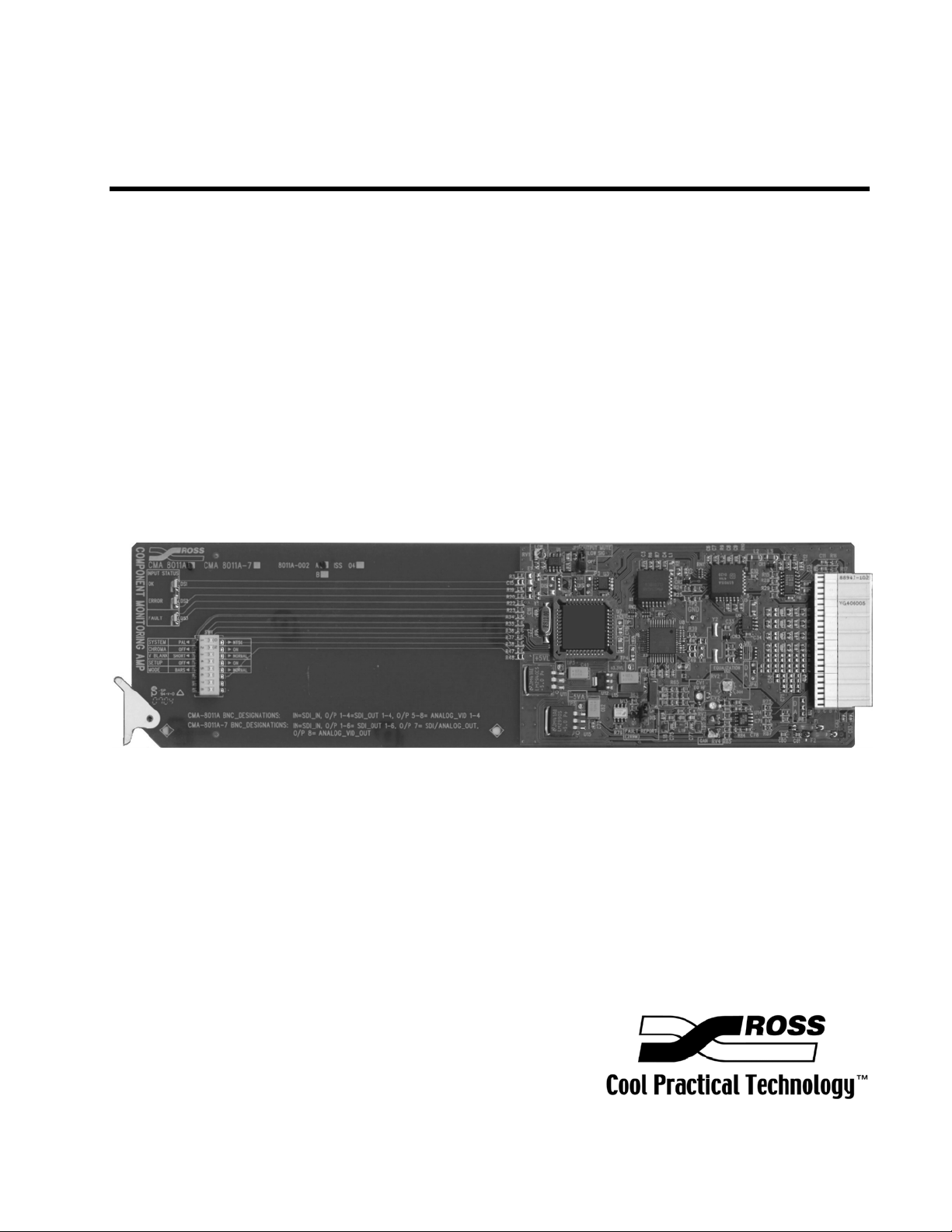
This product is intended to be a component product of the RossGear 8000 series
frame. Refer to the RossGear 8000 series frame User Manual for important safety
instructions regarding the proper installation and safe operation of the frame as well
as it’s component products.
Warning
Certain parts of this equipment namely the power supply area still present a safety
hazard, with the power switch in the OFF position. To avoid electrical shock,
disconnect all A/C power cords from the chassis' rear appliance connectors before
ervicing this area.s
Warning
Service barriers within this product are intended to protect the operator and service
personnel from hazardous voltages. For continued safety, replace all barriers after
any servicing.
This product contains safety critical parts, which if incorrectly replaced may present
a risk of fire or electrical shock. Components contained within the product’s power
supplies and power supply area, are not intended to be customer serviced and should
be returned to the factory for repair.
To reduce the risk of fire, replacement fuses must be the same type and rating.
Only use attachments/accessories specified by the manufacturer.

EMC Notices
US FCC Part 15
This equipment has been tested and found to comply with the limits for a class A Digital device,
pursuant to part 15 of the FCC Rules. These limits are designed to provide reasonable protection
against harmful interference when the equipment is operated in a commercial environment. This
equipment generates, uses, and can radiate radio frequency energy and, if not installed and used in
accordance with the instruction manual, may cause harmful interference to radio communications.
Operation of this equipment in a residential area is likely to cause harmful interference in which case
users will be required to correct the interference at their own expense.
Notice
Changes or modifications to this equipment not expressly approved by Ross Video
Ltd. could void the user’s authority to operate this equipment.
CANADA
This Class “A” digital apparatus complies with Canadian ICES-003.
Cet appareil numerique de classe “A” est conforme à la norme NMB-003 du Canada.
EUROPE
This equipment is in compliance with the essential requirements and other relevant provisions of CE
Directive 93/68/EEC.
INTERNATIONAL
This equipment has been tested to CISPR 22:1997 along with amendments A1:2000 and A2:2002 and
found to comply with the limits for a Class A Digital device.
Notice
This is a Class A product. In domestic environments this product may cause radio
interference in which case the user may have to take adequate measures.
Maintenance/User Serviceable Parts
Routine maintenance to this RossGear product is not required. This product contains no user
serviceable parts. If the module does not appear to be working properly, please contact Technical
Support using the numbers listed under the “Contact Us” section on the last page of this manual. All
RossGear products are covered by a generous 5-year warranty and will be repaired without charge for
materials or labor within this period. See the “Warranty and Repair Policy” section in this manual for
details.

Environmental Information
The equipment that you purchased required the extraction and use of natural resources for its
production. It may contain hazardous substances that could impact health and the environment.
To avoid the potential release of those substances into the environment and to diminish the need for
the extraction of natural resources, Ross Video encourages you to use the appropriate take-back
systems. These systems will reuse or recycle most of the materials from your end-of-life equipment in
an environmentally friendly and health conscious manner.
The crossed-out wheeled bin symbol invites you to use these systems.
If you need more information on the collection, reuse, and recycling systems, please contact your local
or regional waste administration.
You can also contact Ross Video for more information on the environmental performances of our
products.


Contents
Introduction 1-1
In This Chapter .......................................................................................................................1-1
A Word of Thanks....................................................................................................1-1
Overview ..................................................................................................................1-2
Functional Block Diagram .......................................................................................1-2
Features ....................................................................................................................1-3
Documentation Terms ..............................................................................................1-3
Installation and Setup 2-1
In This Chapter .......................................................................................................................2-1
Static Discharge........................................................................................................2-1
Unpacking ................................................................................................................2-1
Analog Output Setup Switches.................................................................................2-2
Output Mute Jumper.................................................................................................2-3
Fault Report (SMPTE 269M) Jumper ......................................................................2-3
Equalization Setting .................................................................................................2-3
Board Installation .....................................................................................................2-3
BNC Labels ..............................................................................................................2-3
Cable Connections....................................................................................................2-4
LEDs.........................................................................................................................2-4
SMPTE 269M Fault Reporting 3-1
In This Chapter .......................................................................................................................3-1
Overview ..................................................................................................................3-1
Jumper Setup ............................................................................................................3-2
Frame Connections...................................................................................................3-2
Details.......................................................................................................................3-2
Specifications 4-1
In This Chapter .......................................................................................................................4-1
CMA-8011A Technical Specifications ....................................................................4-2
Service Information 5-1
In This Chapter .......................................................................................................................5-1
Troubleshooting Checklist .......................................................................................5-1
Warranty and Repair Policy .....................................................................................5-2
Ordering Information 6-1
In This Chapter .......................................................................................................................6-1
CMA-8011A Component Monitoring Amp and Related Products ..........................6-1
CMA-8011A User Manual (Iss.05) Contents •i

ii •Contents CMA-8011A User Manual (Iss.05)

Introduction
In This Chapter
This chapter contains the following information sections:
• A Word of Thanks
• Overview
• Functional Block Diagram
• Features
• Documentation Terms
A Word of Thanks
Congratulations on choosing the Ross Video CMA-8011A Component Monitoring Amplifier. The
CMA-8011A is part of a full line of digital products within the RossGear Terminal Equipment family
of analog and digital products, backed by Ross Video’s experience in engineering and design expertise
since 1974.
You will be pleased at how easily your new CMA-8011A fits into your overall working environment.
Equally pleasing is the product quality, reliability and functionality. Thank you for joining the
worldwide group of satisfied Ross Video customers!
Should you have a question pertaining to the installation and operation of your CMA-8011A, please
contact us at the numbers listed on the last page of this publication. Our technical support staff is
always available for consultation, training, or service.
CMA-8011A User Manual (Iss.05) Introduction •1-1

Overview
The CMA-8011A Component Monitoring Amplifier provides a convenient and cost effective dual-
purpose solution for signal distribution and picture monitoring requirements in serial digital
component (4:2:2) systems. The complete unit occupies only a single card slot in a standard RossGear
8000 series digital products rack frame. Ten modules may be mounted in the 2RU frame, with four
modules in a 1RU frame.
The CMA-8011A addresses high quality imaging requirements by converting the 8 MsB's of an SDI
signal to analog composite video. It uses a 10-bit DAC with a 10MHz bandwidth, thereby achieving
low artifact video output.
The CMA-8011A provides four composite analog monitoring outputs and can work in either NTSC or
PAL environments. In addition to converting the digital signal, the CMA-8011A also outputs four
reclocked SDI streams. The SDI input has an exceptionally good cable equalizer that will give error-
free performance with up to 305 meters (1000 ft.) of Belden 8281 cable.
Several user-selectable settings are available to place the CMA-8011A into the proper operating mode.
Some of these modes are; setting the monitoring outputs to monochrome, output a 75% color bar
pattern and blanking the vertical interval.
Of special interest on the CMA-8011A is the inclusion of an adjustable analog cable equalizer for the
analog output signal. This adjustment can be set to equalize up to 90 meters (300 ft.) of Belden 8281
cable, thus ensuring that the monitoring signal is delivered to the destination without chroma loss.
The CMA-8011A has card-edge LED indicators to confirm adequate serial digital input signal
strength and to indicate monitoring errors.
Functional Block Diagram
Figure 1. Simplified Block Diagram of CMA-8011A Functions
1-2 •Introduction CMA-8011A User Manual (Iss.05)

Features
The following features make the CMA-8011A one of the finest Component Monitoring Amplifiers on
the market today:
• Input and conversion status indicator LED's
• Input level/strength detection
• Auto-reclocking of serial digital input
• Input equalization for up to 305 meters (1000 ft.) of cable
• Four serial digital outputs
• Four NTSC or PAL analog monitoring outputs
• Excellent chroma modulation accuracy
• Cable equalization for monitor outputs
• Fault Reporting (SMPTE 269M)
• Fits Ross Video 8000 series digital products frames
and Leitch*6800 series frames
• 5-year transferable warranty
Documentation Terms
The following terms are used throughout this guide:
• “Frame” refers to the DFR-8104A, and DFR-8110A frames that can house the
CMA-8011A cards. See the respective User Manuals for details.
• “Operator” and “User” both refer to the person who uses the CMA-8011A cards.
• “Board”, “Card”, and “Module” all refer to the CMA-8011A modules, including
all components.
• “System” refers to the mix of interconnected production and terminal equipment in
which the CMA-8011A cards operate.
*Leitch is a trademark of Leitch Technology Corporation
CMA-8011A User Manual (Iss.05) Introduction •1-3

1-4 •Introduction CMA-8011A User Manual (Iss.05)

Installation and Setup
In This Chapter
This chapter contains the following information sections:
• Static Discharge
• Unpacking
• Analog Output Setup Switches
• Output Mute Jumper
• Fault report Jumper
• Equalization Setting
• Board Installation
• BNC Labels
• Cable Connections
• LEDs
Static Discharge
Whenever handling the CMA-8011A cards and other related equipment, please observe all static
discharge precautions as described in the following note:
ESD
Susceptibility
Static discharge can cause serious damage to sensitive
semiconductor devices. Avoid handling circuit boards in high
static environments such as carpeted areas, and when wearing
synthetic fiber clothing. Always exercise proper grounding
precautions when working on circuit boards and related
equipment.
Unpacking
Unpack each CMA-8011A card you received from the shipping container, and check the contents
against the packing list to ensure that all items are included. If any items are missing or damaged,
contact your sales representative or Ross Video directly.
CMA-8011A User Manual (Iss.05) Installation and Setup •2-1

SW1 - Output Setup
JP5 - Fault Report
JP1 - Output Mute
RV2 - EQ
Figure 2. User Control Locations
Analog Output Setup Switches
Use figure 2, the card labeling, and the following discussion to adjust the switch settings to configure
the analog output signal.
Table 1. Switch Settings
Position Reference SW1 Label Description / Function
PAL For 625 line systems
1 SYSTEM
NTSC For 525 line systems
ON The normal position
2 CHROMA
OFF Used to output luminance only for the best picture on a
monochrome monitor.
NORMAL Blanks all vertical interval information signals (20-line
blanking).
3 V BLANK
SHORT
Passes all vertical interval signals occurring after the post-
equalizing pulses. If setup is ON, the signal will be non-
standard because set-up will be applied to the vertical interval.
ON For NTSC - North America
4 SETUP OFF For all other systems
NORMAL Normal operation
5 MODE BARS Produces an analog color bar output.
(Requires a valid 270Mb/s input signal.)
6 - 8 Reserved for future use.
2-2 •Installation and Setup CMA-8011A User Manual (Iss.05)

Output Mute Jumper
Select one of the following options on JP1 as follows, to enable or disable the Output Mute option:
• Low Sig — output will be muted if the input signal degrades to the point that the
input EQ can no longer guarantee error-free performance. When the red ERROR
LED is on, the outputs will be muted.
• Off — the card will work to the limits of the input stage (default setting).
Fault Report (SMPTE 269M) Jumper
Select SMPTE 269M Fault Reporting, ENABLED or DISABLED, via JP5. The default is EN.
See Chapter 3, “SMPTE 269M Fault Reporting” for complete details.
Equalization Setting
Use figure 2, the card labeling, and the following discussion to adjust the CMA-8011A equalization
setting.
Set the analog output EQUALIZATION adjustment (RV2) for the cable length used between the
amplifier and analog destination equipment. Plug the board into the frame and apply power.
The equalization control is calibrated for Belden 8281 cable. For other types of cable, put the board
on the extender, apply a D1 color bar signal and, using a scope, set the EQUALIZATION adjustment
for correct chroma level at the destination.
Board Installation
Use the following steps to install the CMA-8011A cards in a RossGear DFR-8104A or DFR-8110A
digital frame:
1. Refer to the User Manual of the RossGear frame to ensure that the frame is properly
installed according to instructions. If this module is to be installed in any compatible
frame other than a Ross Video product, refer to the frame manufacturer’s manual for
specific instructions.
2. Please note that heat and power distribution requirements within a frame may dictate
specific slot placement of cards. Cards with many heat-producing components
should be arranged to avoid areas of excess heat build-up, particularly in frames
using convectional cooling.
3. After selecting the desired frame installation slot, hold the CMA-8011A card by the
edges and carefully align the card edges with the slots in the frame. Then fully insert
the card into the frame until the rear connection plug is properly seated.
BNC Labels
Affix the supplied BNC label, as per the included instructions, to the BNC area on the rear of the rack
frame.
CMA-8011A User Manual (Iss.05) Installation and Setup •2-3

Cable Connections
The following diagram indicates the input and output connections for coax cables to the CMA-8011A
when mounted in RossGear 8000 series digital frames.
1
IN
3
5
7
2
4
6
8
SDI
Input
SDI
Out 2
SDI
Out 4
Composite
Out 2
Composite
Out 4
SDI
Out 1
SDI
Out 3
Composite
Out 1
Composite
Out 3
Figure 3. Cabling Designations for RossGear 8000 Series Frames
It is not necessary to terminate unused analog or digital outputs.
LEDs
The front edge of the module has several LED indicators, which show the status of the amplifier.
INPUT OK LED
ERROR LED
FAULT LED
Figure 4. LEDs
2-4 •Installation and Setup CMA-8011A User Manual (Iss.05)

The meanings of the LED indicators when lit are as follows:
Table 2. LED Status Indicators
LED Color Status Description
OK Green
The input signal is suitable for achieving error-free
performance. It is within the capability of the cable
equalizer and reclocking circuit to restore the signal.
ERROR Red
This indicates that the input signal is too low or absent.
In some circumstances, the signal may still be restored
correctly but the circuits will be working close to the
limit of their capability and reliability cannot be assured.
Red This indicator identifies a problem either with the input
signal or with the analog conversion section of the card.
Red long flash
90% duty cycle
There is no input signal, or the SDI equalizer is working
at, or beyond, its maximum capability.
FAULT
Red short flash
10% duty cycle
The monitoring amp is on "TEST" mode or the input
signal is not a 4:2:2, 270Mb/s signal (i.e. input signal is
143Mb/s 4Fsc).
CMA-8011A User Manual (Iss.05) Installation and Setup •2-5

2-6 •Installation and Setup CMA-8011A User Manual (Iss.05)

SMPTE 269M Fault Reporting
In This Chapter
This chapter contains the following sections:
• Overview
• Jumper Setup
• Frame Connections
• Details
Overview
The SMPTE 269M Fault Reporting system, also known as a SMPTE “alarm”, provides indication if
one or more frame modules encounter a fault or an abnormal condition. The CMA-8011A module
provides a jumper to enable SMPTE-269M fault reporting. The card connects by means of an internal
interface circuit to an auxiliary telco connector on RossGear 8000 series frames. When the frame
connection is interfaced with a customer-designed system of LEDs or audible alarms, faults can be
traced to a specific frame when a card fault occurs within that frame.
The following diagram illustrates a general arrangement for SMPTE 269M alarm reporting:
Figure 5. SMPTE 269M Alarm Reporting: Internal interface and typical connections
CMA-8011A User Manual (Iss. 05) SMPTE 269M Fault Reporting •3-1

Jumper Setup
If fault reporting for the CMA-8011A is desired, use jumper JP5 - FAULT REPORT (269M) to set
up the card.
1. To access the jumper, remove the card from the frame by pressing down the white
card ejector tab and pulling the card from the frame slot.
2. Observing all static discharge and handling precautions, place the card with the
component side facing up on a clean flat surface.
3. To enable SMPTE fault reporting, set jumper JP5 to EN position.
4. To disable SMPTE fault reporting, set jumper JP5 to DIS position.
JP5 - Fault Report
Figure 6. SMPTE 269M Alarm Reporting Jumper Location
Frame Connections
The SMPTE 269M Fault Reporting connection on RossGear 8000 series frames is provided by the
auxiliary telco connector, AUX A, for interfacing with a customer-designed alarm system.
AUX A Connector for SMPTE 269M
Fault Reporting
Figure 7. SMPTE 269M Alarm Reporting Frame Connections
Details
The fault report contacts are closed when the card detects an internal failure or a power loss condition.
The fault report will pulse closed for 1 to 2 ms every 16ms when the input signal is low, missing, or
invalid.
Some internal failures are:
• Failure of the card to initialize
• Failure in the fault reporting circuitry
• Failure to detect a valid input signal to the card
For additional information on alarm system design, refer to the SMPTE document ANSI/SMPTE
269M - 1999.
3-2 •SMPTE 269M Fault Reporting CMA-8011A User Manual (Iss. 05)
Table of contents
Other Ross Amplifier manuals

Ross
Ross ADA-8504 User manual

Ross
Ross GearLite CMA-9011-R User manual

Ross
Ross ADA-8503 User manual

Ross
Ross DRA-8204 User manual

Ross
Ross ADA-7801 User manual

Ross
Ross SEA-8008 User manual

Ross
Ross TRA-8206 User manual

Ross
Ross ADA-8405-C User manual

Ross
Ross QRA-8808 User manual

Ross
Ross VTA-8060 User manual

Ross
Ross PC6400B User manual

Ross
Ross openGear SRA-8201 User manual

Ross
Ross TEA-8207 User manual

Ross
Ross OpenGear DEA-8805 User manual

Ross
Ross SMA-8018 User manual

Ross
Ross SRA-8901 Series User manual

Ross
Ross ADA-8501 User manual

Ross
Ross GearLite SEA-9003 User manual

Ross
Ross openGear SEA-8203 User manual

Ross
Ross AMA-8511 User manual