Ross RXT250EX User manual

Protect yourself and others by observing all safety information, warnings, and cautions. Failure to
comply with instructions could result in personal injury and/or damage to product or property.
Please retain instructions for future reference!
250AMP
MIG /MMA
INVERTER WELDER
ROSSWELDING RXT250EX

CAUTION!
THIS is a Caution symbol. This symbol is used throughout the user guide whenever there is a risk of
damaging your product. Ensure that these warnings are read and understood at all times.
IMPORTANT
PLEASE read all of the safety and operating instructions carefully before using this product. Please
pay particular attention to all sections of this manual that carry warning symbols and notices.
WARNING!
THIS is a Warning symbol. This symbol is used throughout the manual whenever there is a risk of per-
sonal injury. Ensure that these warnings are read and understood at all times.
GENERAL DESCRIPTION
A general purpose MIG /MMA welder for general purpose workshop use. The power source is an
IGBT inverter.
PRODUCT SPECIFICATION
Item RXT250EX
Input Power 230V
Frequency 50Hz
Phase No. 1
Rated No-load Voltage 53V , < 15 DC (VRD mode)
Maximum Input Current 46 Amp
Rated Input Current 27.2 Amp
MIG
Rated Output 250 Amp
Rated Duty Cycle 35%
Output Range 30-250 Amp
MMA (STICK)
Rated output 225 Amp
Rated Duty Cycle 35%
Output Range 20-225 Amp
VRD Yes

The user of this welder is responsible for his own and the safety of others. It is most important to
read, learn and respect the rules in this user guide.
When using this welder, basic safety precautions, including the following, should be followed
to reduce the risk of re, electric shock and personal injury. Make sure that you have read all of
these instructions before using this welder. Keep this booklet in a safe place for future reference.
Persons who are not familiar with this booklet should not use the welder.
WARNING! SAFETY INSTRUCTIONS
TRAINING
The operator should be properly trained to use the welding machine safely and should be in-
formed about the risks relating to arc welding procedures. This manual does not attempt to cover
welding technique. Training should be sought from qualied/experienced personnel on this as-
pect especially for any welds requiring high integrity for safety.
SERIOUS FIRE RISK
The welding process produces sparks, droplets of fused metal, metal projectiles and fumes. This
constitutes a serious re risk. Make sure that the area around the work piece is clear of all inam-
mable materials. It is advisable to have a re extinguisher to hand.
WORK AREA
Ensure a clear work area with unrestricted movement for the operator. Always maintain easy ac-
cess to the On/Off switch and the mains supply.
THE WORK PIECE
The work piece will remain at a high temperature for a relatively long period. Do not touch the
weld or the work piece unless you are wearing welding gloves. Always use pliers or tongs. Never
touch the welded material with bare hands until it has been allowed to cool.
WELDING SURFACES
Do not weld on containers or pipes that hold, or have held, ammable liquids or combustible
gases.
Do not weld coated, painted or varnished surfaces as the coatings may ignite and or can give off
dangerous fumes.
VENTILATE THE WORK AREA
Arc welding (especially using uxed core wire) emits fumes which can be dangerous. Make sure
that the work area is well ventilated.
AVOID ELECTRICAL CONTACT
Use adequate electrical insulation with regard to the electrode, the work piece and any accessi-
ble) earthed metal parts in the vicinity. Avoid direct contact with the welding circuit. The no load
voltage between the earth clamp and the torch can be dangerous under certain circumstances.
FOR ADDITIONAL PROTECTION FROM ELECTRIC SHOCK
It is recommended that this tool be used in conjunction with a residual current device (RCD)
with a rated residual current of 30mA or less.
CONSIDER WORK AREA ENVIRONMENT
Do not expose the welder to rain. Do not use it in damp, or wet locations. Keep the work area
well lit.

SAFETY INSTRUCTIONS … cont
DRESS PROPERLY
Use protective gloves and re resistant protective clothing when using the welder. Avoid exposing
skin to the ultraviolet rays produced by the arc.
ALWAYS USE THE WELDING MASK
Under no circumstances should the welder be operated unless the welding mask is protecting
the eyes and face. There is a serious risk of eye damage if the mask is not used. The sparks and
metal projectiles can cause serious damage to the eyes and face. The light radiation produced
by the arc can cause damage to eyesight and burns on the skin. Never remove the welding mask
whilst welding. Move the torch away from the work piece and release the trigger switch before
removing the welding mask.
SAFETY GLASSES
After welding use safety glasses when brushing, chipping grinding the slag from the weld.
OTHER PERSONS
Ensure that other persons are screened from the welding arc and are at least 15 metres away
from the work piece. Always ensure that the welding arc is screened from onlookers, or people
just passing by. Use screens if necessary, or non reecting curtains.
KEEP CHILDREN AND ANIMALS AWAY
Do not let children or animals have access to the welding equipment or to the work area.
SWITCHING OFF
When you have nished welding switch off the welder. Do not put the torch down with the welder
switch On and with the wire tted. When leaving the welder unattended, move the On/Off switch
to the Off position and disconnect the welder from the mains supply. Do not leave hot material
unattended after welding.
WELDING CABLES
Keep the welding cables, earth clamp and torch in good condition. Failure to can result in poor
welding quality and could be dangerous in structural situations.
CHECK DAMAGED PARTS
Before further use of the welder, any part that is damaged should be carefully checked to deter-
mine that it will operate properly and perform its intended function. Check for breakage of parts
and any other conditions that may affect its operation. Any part that is damaged should be prop-
erly repaired, or replaced, by an authorised service centre.
IMPROPER USE
Do not use this welder for pipe thawing.
HANDLING
Ensure the handle is correctly tted and always use safe lifting practices when lifting.
CAUTION! - VENTILATE THE WELDER
THERE must always be a sufcient air passage around the welder to allow for the cooling
of the transformer. If the cooling process is obstructed the welder will overheat and the overload
cut out protector will activate and cut off the welding current. If the overload cut out protector activates leave
the welder for at least 15 minutes to cool down before further use.

ADDITIONAL PRECAUTIONS
WELDING OPERATIONS:
In environments with increased risk of electric shock;
In conned spaces; In the presence of ammable or explosive materials;
MUST BE evaluated in advance by an “expert supervisor” and must always be carried
out in the presence of other people trained to intervene in emergencies.
POSITION and HANDLING
Position the welding machine on a horizontal surface that is able to support the weight:
otherwise (e.g. inclined or uneven oors etc.) there is danger of overturning.
The welder MUST NOT be supported by the operator (e.g using belts).
The operator MUST NOT BE ALLOWED to weld in raised positions unless safety plat-
forms are used.
VOLTAGE BETWEEN ELECTRODE HOLDERS OR TORCHES:
Working with more than one welding machine on a single piece or on pieces that are
connected may generate a dangerous accumulation of no-load voltage between two
different electrode holders or torches, the value of which may reach double the allowed
limit.
IMPROPER USE:
It is hazardous to use the welding machine for any work other than that for which it was
designed. Example do not use this welder for pipe thawing. The safety guards and
moving parts of the covering of the welding machine and of the wire feeder should be in
their proper positions before connecting the welding machine to the power supply.
WARNING!
Any manual operation carried out on the moving parts of the wire feeder, for example:
Replacing rollers and/or the wire guide; Inserting wire in the rollers; Loading the wire reel;
Cleaning the rollers and the area underneath them.
Should be carried out with the welding machine switched off and disconnected from the
power supply outlet . Never lift the welding machine when connected to the mains
supply.

WARNING!
When using this welder, provide adequate ventilation or facilities for the removal of weld-
ing fumes near the arc; a systematic approach is needed in evaluating the exposure
limits for the welding fumes, which will depend on their composition, concentration and
the length of the exposure itself. Do not operate on materials cleaned with chlorinated
solvents or near such substances. Remove all ammable materials (e.g. wood, paper,
rags etc.) from the working area.
WARNING!
Do not weld on containers or piping that contains or has contained ammable liquids or
gaseous products. Do not weld on containers under pressure.
WARNING!
This welding machine complies with the requirements of the technical standard for the
product for use only and exclusively in industrial environments and for professional
purposes. It is not guaranteed to meet electromagnetic compatibility requirements in the
home.
WARNING!
When using this welder, always use a welding helmet . Use special re resistant pro-
tective clothing and do not allow the skin to be exposed to the ultra violet and infrared
rays produced by the arc; other people in the vicinity of the arc should be protected by
shields of non-reecting curtains.
WARNING! Do not use in rain or store in locations affected by rain.
WARNING SYMBOLS
The following warning symbols are to remind you of the safety precautions you should take when
using the welder.
WARNING!
Read this User Guide carefully before using the welder and keep it in a safe
place for future reference.
WARNING!
When using this welder, avoid direct contact with the welding circuit. The no-
load voltage supplied by the welding machine can be dangerous in certain
circumstances.

THE RATING PLATE
The rating plate is tted to the welder and displays the following symbols and information.
Mains supply, single phase
A.C. 50/60Hz
Regulatory compliance mark.
Welding Modes
MIG/MMA
Single phase input, frequency
conversion, rectier
X Duty Cycle I2 Welding Current
I1max Maximum Input current U2 Welding Voltage
I1eff Rated input current U0 Open circuit output voltage
U1 Rated input voltage IP21S Protection class

KNOW YOUR WELDER
1
234
5
6
7
8
9
10
14
15
16
17 18
19
20
21
22
23
24
25
11
12
13
REAR PANEL
Wire feed side

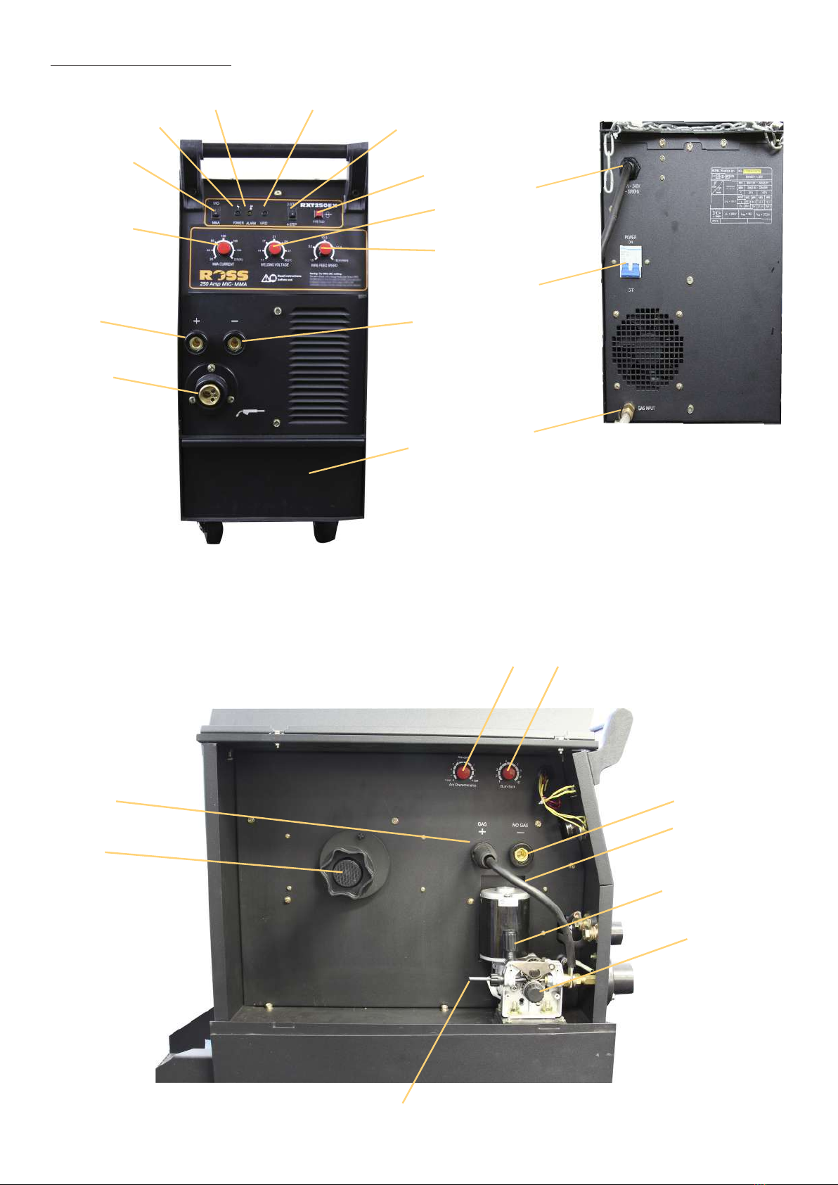
[1] Mode switch MIG /MMA
[2] GREEN Power lamp
[3] ORANGE Alarm/ Temperature lamp
[4] GREEN VRD indicator (MMA mode)
[5] 2 STEP / 4 STEP selector switch (MIG
MODE)
[6] Manual Wire feed. (MIG MODE)
[7] Welding power (MIG MODE)
[8] Wire feed speed control (MIG MODE)
[9] Negative output terminal.
[10] Tool Draw
11 Euro torch connector
12 Positive output terminal
[13] Welding current control (MMA MODE)
[14] Mains input
[15] Power switch
[16] Gas input.
[17] ARC Characteristics
[18] Burn Back control
[19] Positive output terminal
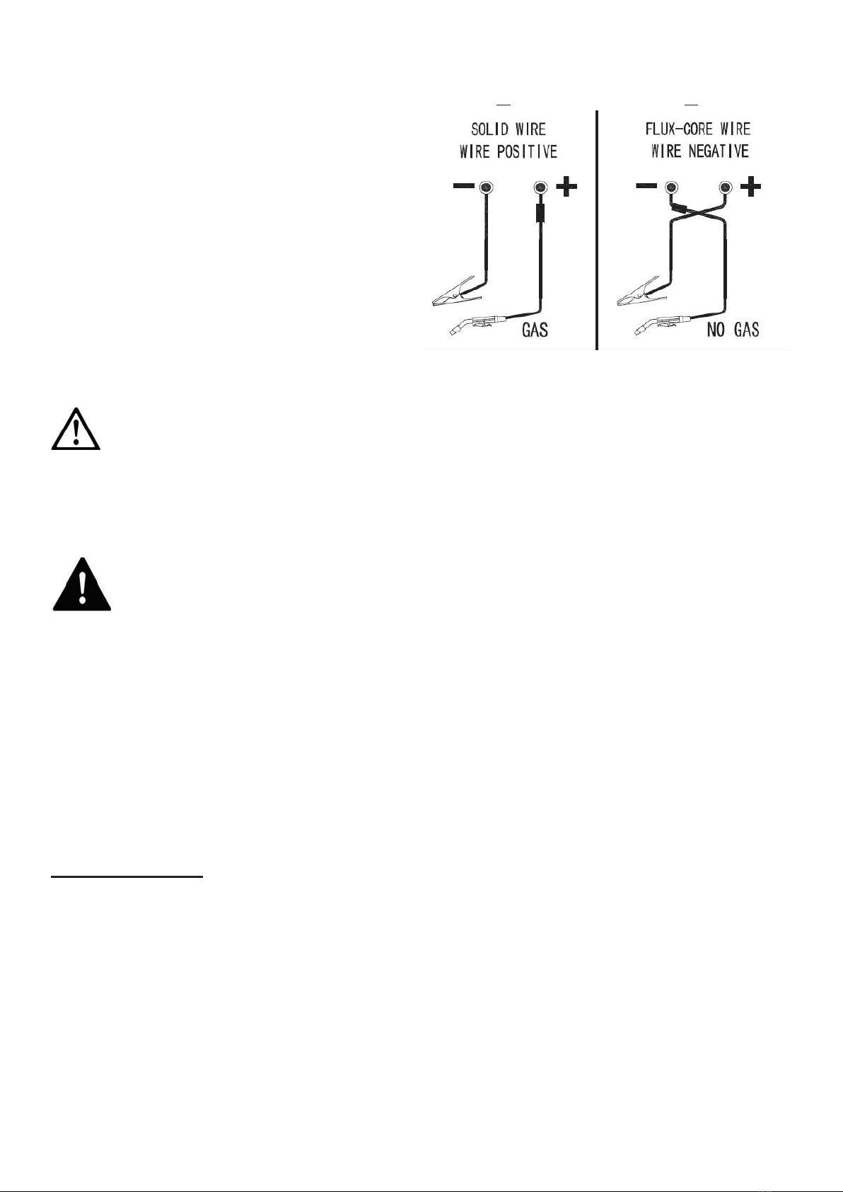
[20] MIG welding polarity selection cable.
[21] Tension screw
[22] Wire feed roller
[23] Guide tube
[24] Reel Holder
[25] Negative output terminal.
LOADING THE WIRE
• SelectMIGmodewiththemodeswitchonthefrontpanel.
• Setthe2 STEP / 4 STEP selector switch [5] to 2 Touch
• Fitthetorchtotheeurotting[11]andrmlytighten.
• Openthesidecoveroftheunit
• Removetheknobfromthewirereelholder[24]andtthewirespoolontothewirereelsothatthewirewill
exitthespoolfromthebottom
• Rettheknob[24].
• Release the tension screw [21] and open the upper roller arm.
• Without letting the wire un-spool, cut the end of the wire of cleanly leaving no kinks the feed
about 30cm of the wire through the guide tube and into the wire liner by hand.
• Thewirefeedroller[22]hastwodifferentsizegroves.Checkthatthewireisalignedwiththecorrectsize
groveinthewirefeedrollerforthetypeofwireandthencarefulclosetheupperrollerandtensionscrew.If
necessaryremovethewirefeedrollerandturnitovertoaccesstheothergroveandret.
At the end of the torch
• Twistthenozzleclockwiseandpulltoremove.
• Unscrew the contact tip counterclockwise and remove. Check that the correct tip size is being
used for the wire being tted.
• Lay the torch sheath out in a straight line so that the wire move through it easily
WARNING! The following steps require applying power to the welder. Do not touch anything with the
torch or wire as it may result in accidental arcing.
• Plugthepowercord[14]intoitselectricaloutlet,setthewirefeedspeedcontrol[8]midwayandturnthe
welderON[15].
• Pressthewirefeedbutton[6]orliftthetorchhandleandcontinuepressingthetrigger
untilthewirefeedsthroughtheendofthetorchabout50mm
Note:Ifthewiredoesnotfeedthrough,viewthewirefeedunitandseeifthewireisbeingpushed.Ifitis
not,turnthewelderOFFandaddmoretensiontothewirefeedadjustingspringandtryagain.
• Oncethewireisexposed,releasethewirefeedbutton[6]orthetrigger
• Slidethecontacttipoverthewireandscrewitintotorchhandle
• Replacethenozzleandcutoffanyexcesswireover10mm
MIG MODE

POLARITY SELECTION
• Thecorrectpolaritymustbesetforthetypeof
welding.
When using solid wire in conjunction with weld-
ing gas, connect the torch to the positive ter-
minal and the earth clamp to the negative. See
diagram A.
When using ux cored wire (gasless) connect
the negative terminal to the welding torch and
the earth clamp to the positive. see diagram B.
CAUTION! Check that the dinse terminals are tight before
commencing to weld to prevent burning
To commence the welding process proceed as follows.
• MakesurethattheearthclampisrmlyconnectedtotheWorkpiece.
WARNING! Ensure that you have your protective clothes, gloves and welding helmet
correctly tted before welding. Do not start welding before your eyes are properly pro-
tected by the welding helmet.
• TurnthewelderswitchedONandtheweldinggasifapplicable.
You are now ready to execute the weld.
• Selecttherequiredweldingvoltage[7]settingweldforthejobathand.
• Bringthewireintocloseproximityoftherequiredweldstartposition.Keepthetipapproximately10-15mm
awayfromtheworkpieceandsqueezethetriggeronthetorchtocommencewelding.
• Adjustthewirefeed[8]ratetoobtaintheoptimumweld
2 STEP / 4 STEP
The 2 STEP /4 STEP switch [5] controls how the machine reacts to the trigger switch on the weld-
ing torch.
2 STEP mode
• Squeezethetriggertostartweldingandreleaseittostop.
4 STEP mode
• Squeezethetriggerandreleasetostartwelding.ToStop,Squeezethetriggerandreleaseagain
A B

THERMOSTATIC PROTECTION
This welder is automatically protected from overheating by a thermal overload cut out protector. If
the transformer overheats the overload cut out protector will activate and cut off. The amber light
will illuminate to show that the cut out has operated.
After cooling the protector will reconnect the supply circuit and the welder will be ready for fur-
ther use.
NOTE: If the duty cycle of the machine is exceeded the thermostatic protection will activate.
There are no user serviceable parts inside the welder. Refer to qualied service personnel if any
internal maintenance is required.
WARNING! Before starting any cleaning, or maintenance procedures on the welding ma-
chine, make sure that it is switched Off and disconnected from the mains supply.
TORCH
Do not put the torch or its cable on hot work pieces; this would cause the insulating materials to
melt, making the torch unusable.
Every time the wire reel is changed, clean out the wire-guide and check the wire liner for build up
of dust and other contaminants. This increases friction and can lead to erratic wire feed and jam-
ming. Replace when necessary.
Daily: Check the wear and correct assembly of the consumable parts at the end of the torch;
swan neck, nozzle, contact tip. Replace when necessary.
WIRE FEEDER
Make frequent checks on the state of wear of the wire feed rollers, regularly remove the metal
dust deposited in the feeder area (rollers and wire-guide in-feed and out- feed)
OTHER
Make sure that the earth clamp is kept clean and in good working order.
Keep the cooling vents clear and clean the outer casing with a soft cloth.
MAINTENANCE CHECKS

GAS BOTTLE AND REGULATOR
For gas shield welding connect the
output of the regulator to the barb at the
rear of the unit and secure.
Welding gas
Eg.
Co2 or Co2/ Argon
WARNING! - Secure the gas bottle
MMA (ARC) WELDING
Warning ! For MMA (ARC) welding.
This unit is fitted with a Voltage Reduction Device (VRD).
TheVRDlamponthefrontpanelisILLUMINATEDwhenoperationinreducedvoltagemode.Then
thislampisOFFindicatesthattheoutputvoltagemaynotbereduced.
VRD (MMA mode)
The VRD is an addition safety feature which reduces the open circuit voltage at the output terminal
when then the unit is not welding.
Note:
This feature can not be turned OFF.
• SelectMMAmodeonthemodeselectionswitch[1].
• ConnecttheNegative (-) output terminal [9] to the earth clamp lead.
• Connect the earth clamp to the job.
• Connect the Positive (+) output terminal [12] to the electrode holder.
Note the electrode holder and cable is not supplied and must be purchased separately.
• Turn the power on [15]
• Select the desired welding current using the welding current control [13]
CAUTION!
When tting the welding leads to the unit, twist the plugs clockwise and ensure that they are
tight in the sockets. Loose connectors will overheat, damage the unit and void warranty.

Welding gas
Eg.
Co2 or Co2/ Argon
ARC WELDING PROCEDURE
Before commencing, make sure that your hand held welding mask or welding helmet is in position to
protect your eyes. It is also advisable to wear gloves and clothing, which cover the hands and arms to
prevent ash burns.
Striking Arc. This is done by bringing the electrode into contact with the work piece using a light tap-
ping action and withdrawing to create a gap of (1.5 mm – 3.00 mm.).
Maintaining Arc. Having created an arc, all that is necessary to maintain it is to proceed steadily in one
direction keeping the gap between the electrode and the work piece constant. The electric current
will ow through the electrode, across the arc gap, and in doing so will melt the electrode core wire
and protective ux. The electrode length will gradually decrease as the metal is transferred to the work
piece under a protective slag formed by the ux. This slag can then be removed when cooled by lightly
tapping with a pointed tool or a welders chipping hammer.
To stop welding, all that is required is to withdraw the electrode from the work piece - thus break-
ing the circuit. Be careful with the end of the electrode, as it will be hot! Provided the current setting
is correct, the surface of the work piece will also melt by the intensity of the electric arc. A degree of
“penetration” is thereby obtained and a complete “fusion” of the work piece and the deposited elec-
trodes met
Selection of electrode. There is no hard and fast rule by which a particular gauge of electrode is select-
ed. Usually this is determined by, the type of weld required and the thickness of the work piece. E.g. a
butt weld in (1.5mm.) sheet metal can be done by a 1.6mm or 2.5mm electrode, the difference being
that the 2.5mm electrode will do the job quicker. The table below Gives guidance as to which elec-
trode is most suitable according to the material thickness. This table is only a guide, and values given
are an indication only.
Tip! Keep the welding current as low as possible for the job at hand to maintain the best duty cycle
from you welding machine, prevent the ux from burning and make removal of slag easier.
Amperage Selection Guide
Rod Size Welding Current
1.6mm 40 - 50 Amps
2.0mm 50 - 75 Amps
2.5mm 75 - 105 Amps
3.2mm 105 - 135 Amps
4.0mm 135 - 190 Amps

No. Breakdown Analysis Solutions
1 No current output No voltage input Check the fuse and or
circuit breaker
Wrong Fuse or break-
er rating
Replace with correct
rating fuse or breaker
Thermal over load
lamp lit
Allow the unit to cool
2 Bad wire feed Low wire feed pres-
sure
Tighten the wire ten-
sion adjustment nut
No back tension on
reel
Check the wire spool
clip
Wire is oxidised Replace wire spool.
Replace liner
3 Poor weld penetration Low input voltage Check that if input
voltage is the same
with rated voltage
Bad connection Check grounding ca-
ble/ clamp, make sure
of a good connection.
Contact tip worn Replace contact tip
4 Porosity in weld No gas ,little gas or
wrong gas
Check all gas
Blockage of gas line Use compress air to
clear the Blockage
Torch valve has been
blocked
Open the welding
torch and check
Bad gas and wire Gas must be dry, use
another type wire
5 No wire feed Control wire broken
or Faulty switch in the
handle
Check by inspection
Wire Control PCB
faulty
Replace the PCB
TROUBLESHOOTING GUIDE

Notes

For information on all ROSS products
please visit: www.rosstools.com.au
The ROSS logo and Bull device are trademarks of J.W. Ross Pty Ltd.
WARRANTY
Our goods come with guarantees that cannot be excluded under the Australian Consumer Law.
You are entitled to a replacement or refund for a major failure and for compensation for any other
reasonably foreseeable loss or damage. You are also entitled to have the goods repaired or re-
placed if the goods fail to be of acceptable quality and the failure does not amount to a major
failure.
This product is guaranteed against faulty materials and workmanship for 12 months from the date
of purchase.
Please retain your receipt as proof of purchase.
This warranty does not cover defects caused by or resulting from:
(a) misuse, abuse or neglect;
(b) trade, professional or hire use;
(c) repairs attempted by anyone other than our authorised repair centres; or
(d) damage caused by foreign objects, substances or accident.
WARRANTY EXCLUSIONS
Wear parts or service related parts required when performing normal and regular maintenance
of this product are not covered by warranty unless it is found to be defective by an Authorised
Service Centre.
Consumable items such as swan necks, nozzles, contacts tips, wire liners etc are not covered by
warranty.
Distributed in Australia by WHITE INTERNATIONAL
PO Box 304 Milperra LPO, NSW, Australia, 2214
Inquiries phone 1800 251 338
THE WHITE INTERNATIONAL policy is one of continuous improvement and the company
reserves the right to the alter designs, colours and specications without notice.
Table of contents
Other Ross Welding System manuals

Ross
Ross RXT150E Instruction manual

Ross
Ross RXT140P User manual

Ross
Ross RXT180ACDC User manual

Ross
Ross RXT100P Instruction manual

Ross
Ross RXT175P User manual

Ross
Ross RXT180E User manual

Ross
Ross RXT150P Quick start guide

Ross
Ross RXT200EX User manual

Ross
Ross RXT170P User manual

Ross
Ross RXT135E User manual