Rosslare R-805 Series User manual

Introduction
The RSDP-805 series expansion boards can be installed directly on top of the AC-825IP or installed on the wall and
fitted on a DIN rail as an expansion board with RS-485 communication to the AC-825IP OSDP/RSDP-Bus (serial bus).
When an RSDP-805 expansion board is used with Rosslare’s AxTraxPro™ Access Control Management Software, the
expansion board supports SIA Open Supervised Device Protocol (OSDP V2) including OSDP-SC (secure channel).
The available RSDP-805 models are:
•R-805 Series: 16-Output Expansion Board
•S-805 Series: 16-Input Expansion Board
•D-805 Series: 4-Door Expansion Board
•P-805 Series: 16-Input, 8-Output Expansion Board
www.rosslaresecurity.com 1
RSDP-805 Series
Expansion Boards for
AC-825IP
Installation Guide

R-805 Series
Expansion Boards for AC-825IP
Installation Guide
1. Introduction
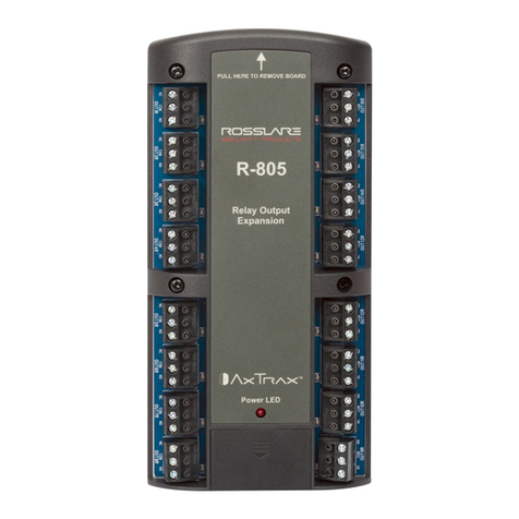
The R-805 is a 16-output expansion board for the AC-825IP access control panel.
The expansion board supports 16-relays (5 A Form-C) for general purpose and security application .
2. Technical Specifications
Electrical Characteristics
Input Voltage 12 to 16 VDC
Input Current
(not including attached devices)
Standby: 65 mA, 12 VDC
Maximum: 700 mA
Number of Outputs 16
Output Relays 5 A with N.O., N.C., and COM contacts Form-C Relays
RS-485 Communication Ports OSDP/RSDP bus (S-bus)
Tamper Input
(from enclosure) 4-pin tamper connector
Environmental Characteristics
Operating Environment Indoor
Operating Temp. Range 0°C to 50°C (32°F to 122°F)
Operating Humidity Range 0% to 85% (non-condensing)
Physical Characteristics
Dimensions (H x W x D) 178 x 87 x 38 mm (7.0 x 3.4 x 1.5 in.)
Weight 315 g (11.2 oz)
Relays Characteristics
Operation Voltage 12 VDC
Operation Current 40 mA
Number of Relays 16
Relay Type Form-C (NO/COM/NC)
Relay Out[put Rated 5 A @ 30 VDC or 5 A @ 30 VAC, 0.6 power factor
LED Indicators
Power LED Active when connected to a power source
Output LED 16 LEDs
Each output LED is active when an output relay is energized.
RSDP-805 Series Installation Guide
www.rosslaresecurity.com 2

3. Wiring Instructions
To wire the R-805 expansion board:
1. Connect the RS-485 communication terminal block to the OSDP/RSDP-bus (serial bus) on the AC-825IP panel.
For more information, see the AC-825IP Hardware Installation and User Manual.
2. Connect the 16-outputs to your various applications.
For RS-485 communication, use a maximum of 1,200 m (4,000 ft) cable length and minimum 22 AWG.
4. Operating the R-805
When a R-805 expansion board is used with a AC-825IP access control panel, it is necessary to define output types
from the Groups element in the tree view in the AxTraxNG/AxTraxPro Access Control Management Software. Output
functions are defined using the Links element within each panel tree menu item.
For more information, see the AxTraxNG User Guide or the AxTraxPro Desktop Client User Guide.
When a R-805 expansion board is used with a AC-825IP access control panel, the unit must be set to installation
mode in the AxTraxNG/AxTraxPro Access Control Management Software as given below .
1. Turn off power.
2. Set all four DIP switches to ON.
3. Turn on power.
4. Wait three seconds. In 30 seconds or less set all four DIP switches to OFF.
The Transmit Data (TX) LED light blinks red.
RSDP-805 Series Installation Guide
www.rosslaresecurity.com 3

S-805 Series
Expansion Boards for AC-825IP
Installation Guide
1. Introduction
The S-805 is a 16-input expansion board for the AC-825IP access control panel.
The expansion board supports 16-supervised inputs for general purpose and security application .
2. Technical Specifications
Electrical Characteristics
Input Voltage 12 to 16 VDC
Input Current
(not including attached devices)
Standby: 70 mA, 12 VDC
Maximum: 75 mA
Number of Inputs 16
Supervised Inputs Voltage 5 VDC maximum voltage
RS-485 Communication Ports OSDP/RSDP bus (S-bus)
Tamper Input
(from enclosure) 4-pin tamper connector
Environmental Characteristics
Operating Environment Indoor
Operating Temp. Range 0°C to 50°C (32°F to 122°F)
Operating Humidity Range 0% to 85% (non-condensing)
Physical Characteristics
Dimensions (H x W x D) 178 x 87 x 38 mm (7.0 x 3.4 x 1.5 in.)
Weight 232 g (8.2 oz)
Output Power Characteristics
Output Voltage 10-12 VDC
Maximum Output Current 800 mA
LED Indicators
Power LED Active when connected to a power source
RSDP-805 Series Installation Guide
www.rosslaresecurity.com 4

3. Wiring Instructions
To wire the S-805 expansion board:
1. Connect the RS-485 communication terminal block to the OSDP/RSDP-bus (serial bus) on the AC-825IP panel.
For more information, see the AC-825IP Hardware Installation and User Manual.
2. Connect the 16-inputs to your various applications.
For RS-485 communication, use a maximum of 1,200 m (4,000 ft) cable length and minimum 22 AWG.
4. Operating the S-805
When a S-805 expansion board is used with a AC-825IP access control panel, it is necessary to define input types
from the Groups element in the tree view in the AxTraxNG/AxTraxPro Access Control Management Software. Input
functions are defined using the Links element within each panel tree menu item.
For more information, see the AxTraxNG User Guide or the AxTraxPro Desktop Client User Guide.
When a S-805 expansion board is used with a AC-825IP access control panel, the unit must be set to installation
mode in the AxTraxNG/AxTraxPro Access Control Management Software as given below .
1. Turn off power.
2. Set all four DIP switches to ON.
3. Turn on power.
4. Wait three seconds. In 30 seconds or less set all four DIP switches to OFF.
The Transmit Data (TX) LED light blinks red.
RSDP-805 Series Installation Guide
www.rosslaresecurity.com 5

D-805 Series
Expansion Boards for AC-825IP
Installation Guide
1. Introduction
The D-805 is a 4-door expansion board for the AC-825IP access control panel.
The expansion board supports four Wiegand readers and four doors with two supervised inputs, including one relay
output for each door.
2. Technical Specifications
Electrical Characteristics
Input Voltage 12 to 16 VDC
Input Current
(not including attached devices)
Standby: 65 mA, 12 VDC
Maximum: 220 mA
Number of Reader Ports 4
Number of Inputs 8
Number of Outputs 4
Output Relays 5 A with N.O., N.C., and COM contacts Form-C Relays
Supervised Inputs Voltage 5 VDC maximum voltage
RS-485 Communication Port OSDP/RSDP-bus (S-bus)
Tamper Input
(from enclosure) 4-pin tamper connector
Environmental Characteristics
Operating Environment Indoor
Operating Temp. Range 0°C to 50°C (32°F to 122°F)
Operating Humidity Range 0% to 85% (non-condensing)
Physical Characteristics
Dimensions (H x W x D) 178 x 87 x 38 mm (7.0 x 3.4 x 1.5 in.)
Weight 268 g (9.5 oz)
Reader Characteristics
Reader Output Voltage 10-12 VDC
Maximum Reader Current 245 mA
LED Control Output Open collector, Active Low
Tamper Input TTL input 5 VDC
Supported Formats Various (see the AxTraxNG User Guide or the AxTraxPro Desktop Client User Guide)
LED Indicators
Power LED Active when connected to a power source
Output LED Four LEDs
Each output LED is active when an output relay is energized.
RSDP-805 Series Installation Guide
www.rosslaresecurity.com 6

3. Wiring Instructions
The reader terminal supports the reader's two data lines. For Wiegand readers, these are data lines D0 and D1. For
Clock & Data readers, D0 is the DATA line and D1 is the CLOCK line.
There is also support for a tamper signal input from the reader and for one LED control output to the reader.
Proximity and keypad readers are supplied with a limited cable. The color of the cable cover represents the cable’s
function.
In general, the cable length should be no more than 150 m (500 ft) with an 18 AWG cable. See each reader's
installation guide for specific details.
To wire the D-805 expansion board:
1. Connect the RS-485 communication terminal block to the OSDP/RSDP-bus (serial bus) on the AC-825IP panel.
For more information, see the AC-825IP Hardware Installation and User Manual.
For RS-485 communication, use a maximum of 1,200 m (4,000 ft) cable length and minimum 22 AWG.
4. Operating the D-805
When a D-805 expansion board is used with a AC-825IP access control panel, it is necessary to define input and
output types from the Groups element in the tree view in the AxTraxNG/AxTraxPro Access Control Management
Software. Input and output functions are defined using the Links element within each panel tree menu item.
For more information, see the AxTraxNG User Guide or the AxTraxPro Desktop Client User Guide.
When a D-805 expansion board is used with a AC-825IP access control panel, the unit must be set to installation
mode in the AxTraxNG/AxTraxPro Access Control Management Software as given below .
1. Turn off power.
2. Set all four DIP switches to ON.
RSDP-805 Series Installation Guide
www.rosslaresecurity.com 7

P-805 Series
Expansion Boards for AC-825IP
Installation Guide
1. Introduction
The P-805 is a 16-Input, 8-Output expansion board for the AC-825IP access control panel.
The expansion board supports 16-supervised inputs and 8 relays (5 A Form-C) for general purpose and security
application .
2. Technical Specifications
Electrical Characteristics
Input Voltage 12 to 16 VDC
Input Current
(not including attached devices)
Standby: 65 mA, 12 VDC
Maximum: 380 mA
Number of Inputs 16
Supervised Inputs Voltage 5 VDC maximum voltage
Number of Outputs 8
Output Relays 5 A with N.O., N.C., and COM contacts Form-C Relays
RS-485 Communication Port OSDP/RSDP-bus (S-bus)
Tamper Input
(from enclosure) 4-pin tamper connector
Environmental Characteristics
Operating Environment Indoor
Operating Temp. Range 0°C to 50°C (32°F to 122°F)
Operating Humidity Range 0% to 85% (non-condensing)
Physical Characteristics
Dimensions (H x W x D) 178 x 87 x 38 mm (7.0 x 3.4 x 1.5 in.)
Weight 284 g (10 oz)
Reader Characteristics
Operation Voltage 10-12 VDC
Operation Current 40 mA
Number of Relays 8
Relay Type Form-C (NO/COM/NC)
Relay Out[put Rated 5 A @ 30 VDC or 5 A @ 30 VAC, 0.6 power factor
LED Indicators
Power LED Active when connected to a power source
Output LED 8 LEDs
Each output LED is active when an output relay is energized.
RSDP-805 Series Installation Guide
www.rosslaresecurity.com 9

3. Wiring Instructions
To wire the P-805 expansion board:
1. Connect the RS-485 communication terminal block to the OSDP/RSDP-bus (serial bus) on the AC-825IP panel.
For more information, see the AC-825IP Hardware Installation and User Manual.
2. Connect the 16 inputs and 8 outputs to your various applications.
For RS-485 communication, use a maximum of 1,200 m (4,000 ft) cable length and minimum 22 AWG.
4. Operating the P-805
When a P-805 expansion board is used with a AC-825IP access control panel, it is necessary to define input and
output types from the Groups element in the tree view in the AxTraxNG/AxTraxPro Access Control Management
Software. Input and output functions are defined using the Links element within each panel tree menu item.
For more information, see the AxTraxNG User Guide or the AxTraxPro Desktop Client User Guide.
When a P-805 expansion board is used with a AC-825IP access control panel, the unit must be set to installation
mode in the AxTraxNG/AxTraxPro Access Control Management Software as given below .
1. Turn off power.
2. Set all four DIP switches to ON.
3. Turn on power.
4. Wait three seconds. In 30 seconds or less set all four DIP switches to OFF.
The Transmit Data (TX) LED light blinks red.
RSDP-805 Series Installation Guide
www.rosslaresecurity.com 10

UL 294 7th Edition
The following labeled R-805, S-805, D-805, P-805 are UL listed to UL 294 7th Edition Standard for Access Control
System Units. It has the following Access Control Performance Ratings:
Destructive Attack Level I
Endurance Level IV
Line Security Level I
Standby Power Level II
Limited Warranty
The full ROSSLARE Limited Warranty Statement is available in the Quick Links section on the ROSSLARE website at
www.rosslaresecurity.com.
Rosslare considers any use of this product as agreement to the Warranty Terms even if you do not review them.
www.rosslaresecurity.com 11
0706-0960603+03
RSDP-805 Series Installation Guide
All product names, logos, and brands are property of their respective owners.
DISCLAIMER: The data contained within Rosslare’s materials or documentation is intended to provide only general information about products available for purchase from Rosslare Enterprises Ltd. and
its associated companies (“Rosslare”). Reasonable efforts have been made to ensure the accuracy of this information. However, it might contain typographic errors, inaccuracies, or omissions that may
relate to product descriptions, visual pictures, specifications, and other details. All technical specifications weights, measures and colors shown, are best approximations. Rosslare can not be held
responsible and assumes no legal liability for the accuracy or completeness of the information provided. Rosslare reserves the right to change, delete, or otherwise modify the information, which is
represented, at any time, without any prior notice.
© 2022 Rosslare Enterprises Ltd. All rights reserved.
For more information regarding support, visit https://support.rosslaresecurity.com.
Other manuals for R-805 Series
2
This manual suits for next models
7
Table of contents
Other Rosslare Computer Hardware manuals