Rosslare R-805 Series User manual

R/S/D/P-805 Family
Expansion Boards for AC-825IP
Installation Manual
Models:
R-805 – 16-Output Expansion Board
S-805 – 16-Input Expansion Board
D-805 – 4-Door Expansion Board
P-805 – 16-Input, 8-Output Expansion Board
R-805 S-805 D-805 P-805

R-805
16-Output Expansion Board
Installation Manual
2
1. Introduction
The R-805 is a 16-output expansion board for the AC-825IP access
control panel.
The R-805 can be installed directly on top of the AC-825IP or installed
on the wall and fitted on a DIN rail as an expansion board with RS-485
communication to the AC-825IP OSDP/RSDP-Bus (S-Bus).
The expansion board supports 16-relays (5 A Form-C) for general
purpose and security application
Figure 1: R-805
2. Technical Specifications
2.1 Electrical Characteristics
Input Voltage 12–16 VDC
Input Current
(not including attached devices)
Standby: 65 mA, 12 VDC
Maximum: 700 mA
Number of Outputs 16
Output Relays 5
A with N.O., N.C., and COM contacts
Form-C Relays
RS-485 Communication Port OSDP/RSDP-bus (S-bus)
Tamper Input (from enclosure) 4-pin tamper connector
2.2 17BEnvironmental Characteristics
Operating Environment Indoor
Operating Temp. Range 0°C to 50°C (32°F to 122°F)
Operating Humidity Range 0 to 85% (non-condensing)
2.3 18BPhysical Characteristics
Dimensions (L x W x D) 178 x 87 x 38 mm (7.0 x 3.4 x 1.5 in.)
Weight 315 g (11.2 oz)
2.4 19BRelays Characteristics
Operation Voltage 12 VDC
Operation Current 40 mA
Number of Relays 16
Relay Type Form-C (NO/COM/NC)
Relay Output Rated 5 A @ 30 VDC or 5 A @ 30 VAC, 0.6 power
factor
2.5 20BLED Indicators
Power LED Active when connected to a power source
Output LEDs 16 LEDs
Each output LED is active when an output relay is
energized
3. 2BWiring Instructions
To wire the R-805 expansion:
1. Connect the RS-485 communication terminal block to the AC-
825IP OSDP/RSDP-bus (S-bus) using daisy chain methodology.
2. Connect the 16-outputs to your various applications (Figure 2).
For RS-485 communication, use a maximum of 1,200 m (4,000
ft) cable length and minimum 22 AWG.
Figure 2: Wiring the R-805 Outputs
4. 3BOperating the R-805
When using AC-825IP and R-805 with AxTraxNG, define output types
from the Groups element in the Tree View. Output functions are
defined using the Links element within each Panel tree menu item.
For more information, refer to the
AxTraxNG Software Manual
.

S-805
16-Input Expansion Board
Installation Manual
3
5. Introduction
The S-805 is a 16-input expansion board for the AC-825IP access
control panel.
The S-805 can be installed directly on top of the AC-825IP or installed
on the wall and fitted on a DIN rail as an expansion board with RS-485
communication to the AC-825IP OSDP/RSDP-Bus (S-Bus).
The expansion board supports 16-supervised inputs for general
purpose and security application.
Figure 3: S-805
6. Technical Specifications
6.1 Electrical Characteristics
Input Voltage 12–16 VDC
Input Current
(not including attached devices)
Standby: 70 mA, 12 VDC
Maximum: 75 mA
Number of Inputs 16
Supervised Inputs Voltage 5 VDC maximum voltage
RS-485 Communication Port OSDP/RSDP-bus (S-bus)
Tamper Input (from enclosure) 4-pin tamper connector
6.2 Environmental Characteristics
Operating Environment Indoor
Operating Temp. Range 0°C to 50°C (32°F to 122°F)
Operating Humidity Range 0 to 85% (non-condensing)
6.3 Physical Characteristics
Dimensions (L x W x D) 178 x 87 x 38 mm (7.0 x 3.4 x 1.5 in.)
Weight 232 g (8.2 oz)
6.4 Output Power Characteristics
Output Voltage 10–12 VDC
Max. Output Current 800 mA
6.5 LED Indicators
Power LED Active when connected to a power source
7. Wiring Instructions
To wire the S-805 expansion:
1. Connect the RS-485 communication terminal block to the AC-
825IP OSDP/RSDP-bus (S-bus) using daisy chain methodology.
2. Connect the 16-inputs to your various applications (Figure 4).
For RS-485 communication, use a maximum of 1,200 m (4,000
ft) cable length and minimum 22 AWG.
Figure 4: Wiring the S-805 Inputs
8. Operating the S-805
When using AC-825IP and S-805 with AxTraxNG, define input types
from the Groups element in the Tree View. Input functions are defined
using the Links element within each Panel tree menu item.
For more information, refer to the
AxTraxNG Software Manual
.

D-805
4-Door Expansion Board
Installation Manual
4
9. Introduction
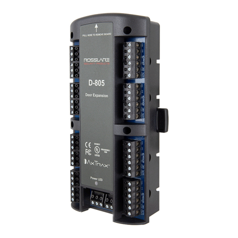
The D-805 is a 4-door expansion board for the AC-825IP access control
panel.
The D-805 can be installed directly on top of the AC-825IP or installed
on the wall and fitted on a DIN rail as an expansion board with RS-485
communication to the AC-825IP OSDP/RSDP-Bus (S-Bus).
The expansion board supports four Wiegand readers and four doors
with two supervised inputs, including one relay output for each door.
Figure 5: D-805
10. Technical Specifications
10.1 Electrical Characteristics
Input Voltage 12–16 VDC
Input Current
(not including attached devices)
Standby: 65 mA, 12 VDC
Maximum: 220 mA
Number of Reader Ports 4
Number of Inputs 8
Number of Outputs 4
Output Relays 5
A with N.O., N.C., and COM contacts
Form-C Relays
Supervised Inputs Voltage 5 VDC maximum voltage
RS-485 Communication Port OSDP/RSDP-bus (S-bus)
Tamper Input (from enclosure) 4-pin tamper connector
10.2 27BEnvironmental Characteristics
Operating Environment Indoor
Operating Temp. Range 0°C to 50°C (32°F to 122°F)
Operating Humidity Range 0 to 85% (non-condensing)
10.3 28BPhysical Characteristics
Dimensions (L x W x D) 178 x 87 x 38 mm (7.0 x 3.4 x 1.5 in.)
Weight 268 g (9.5 oz)
10.4 29BReader Characteristics
Reader Output Voltage 10–12 VDC
Max. Reader Current 245 mA
LED Control Output Open collector, Active low
Tamper Input TTL input 5 VDC
Supported Formats Various (refer to the AxTraxNG™ software manual)
10.5 30BLED Indicators
Power LED Active when connected to a power source
Output LEDs Four LEDs
Each output LED is active when an output relay is
energized
11. 10BWiring Instructions
The reader terminal supports the reader's two data lines. For Wiegand
readers, these are data lines D0 and D1. For Clock & Data readers, D0
is the DATA line and D1 is the CLOCK line.
There is also support for a tamper signal input from the reader and for
one LED control output to the reader.
Proximity and keypad readers are supplied with a limited cable. The
color of the cable cover represents the cable’s function.
In general, the cable length should be no more than 150 m (500 ft)
with an 18 AWG cable. Refer to each reader's installation guide for
specific details.
To wire the D-805 expansion:
1. Connect the RS-485 communication terminal block to the AC-
825IP OSDP/RSDP-bus (S-bus) using daisy chain methodology as
shown in Figure 6.
For RS-485 communication, use a maximum of 1,200 m (4,000
ft) cable length and minimum 22 AWG.
Figure 6: Wiring the D-805
12. 11BOperating the D-805
When using AC-825IP and D-805 with AxTraxNG, define input and
output types from the Groups element in Tree View. Input and output
functions are defined using the Links element within each Panel tree
menu item.
For more information, refer to the
AxTraxNG Software Manual
.

P-805
16-Input, 8-Output Expansion Board
Installation Manual
5
13. Introduction
The P-805 is a 16-Input, 8-Output expansion board for the AC-825IP
access control panel.
The P-805 can be installed directly on top of the AC-825IP or installed
on the wall and fitted on a DIN rail as an expansion board with RS-485
communication to the AC-825IP OSDP/RSDP-Bus (S-Bus).
The expansion board supports 16-supervised inputs and 8 relays (5 A
Form-C) for general purpose and security application.
Figure 7: P-805
14. Technical Specifications
14.1 Electrical Characteristics
Input Voltage 12–16 VDC
Input Current
(not including attached devices)
Standby: 65 mA, 12 VDC
Maximum: 380 mA
Number of Inputs 16
Supervised Inputs Voltage 5 VDC maximum voltage
Number of Outputs 8
Output Relays 5
A with N.O., N.C., and COM contacts
Form-C Relays
RS-485 Communication Port OSDP/RSDP-bus (S-bus)
Tamper Input (from enclosure) 4-pin tamper connector
14.2 32BEnvironmental Characteristics
Operating Environment Indoor
Operating Temp. Range 0°C to 50°C (32°F to 122°F)
Operating Humidity Range 0 to 85% (non-condensing)
14.3 33BPhysical Characteristics
Dimensions (L x W x D) 178 x 87 x 38 mm (7.0 x 3.4 x 1.5 in.)
Weight 284 g (10 oz)
14.4 34BReader Characteristics
Operation Voltage 10–12 VDC
operation Current 40 mA
Number of Relays 8
Relay Type Form-C [NO/COM/NC]
Relay Output Rated 5 A @ 30 VDC or 5 A @ 30 VAC, 0.6 power
factor
14.5 35BLED Indicators
Power LED Active when connected to a power source
Output LEDs 8 LEDs
Each output LED is active when an output relay is
energized
15. 14BWiring Instructions
To wire the P-805 expansion:
1. Connect the RS-485 communication terminal block to the AC-
825IP OSDP/RSDP-bus (S-bus) using daisy chain methodology.
2. Connect the 16 inputs and 8 outputs to your various applications
(Figure 8).
For RS-485 communication, use a maximum of 1,200 m (4,000
ft) cable length and minimum 22 AWG.
Figure 8: Wiring the P-805 Inputs and Outputs
16. 15BOperating the P-805
When using AC-825IP and P-805 with AxTraxNG, define input and
output types from the Groups element in the Tree View. Input and
output functions are defined using the Links element within each Panel
tree menu item.
For more information, refer to the
AxTraxNG Software Manual
.

6
Limited Warranty
The full ROSSLARE Limited Warranty Statement is available in the Quick
Links section on the ROSSLARE website at www.rosslaresecurity.com.
Rosslare considers any use of this product as agreement to the
Warranty Terms even if you do not review them.
Contact Information
Asia Pacific, Middle East, Africa
Rosslare Enterprises Ltd.
Kowloon Bay, Hong Kong
Tel: +852 2795-5630
Fax: +852 2795-1508
support.apac@rosslaresecurity.com
United States and Canada
Rosslare Security Products, Inc.
Southlake, TX, USA 76092
Toll Free: +1-866-632-1101
Local: +1-817-305-0006
Fax: +1-817-305-0069
support.na@rosslaresecurity.com
Europe
Rosslare Israel Ltd.
Rosh HaAyin, Israel 48091
Tel: +972 3 938-6838
Fax: +972 3 938-6830
support.eu@rosslaresecurity.com
Latin America
Rosslare Latin America
Buenos Aires, Argentina
Tel: +54-11-4001-3104
support.la@rosslaresecurity.com
China
Rosslare Electronics (Shenzhen) Ltd.
Shenzhen, China
Tel: +86 755 8610 6842
Fax: +86 755 8610 6101
support.cn@rosslaresecurity.com
India
Rosslare Electronics India Pvt Ltd.
Tel/Fax: 91 20 40147830
Mobile: 91 9975768824
sales.in@rosslaresecurity.com
www.rosslaresecurity.com
0706-0960603+00
Other manuals for R-805 Series
2
This manual suits for next models
3
Table of contents
Other Rosslare Computer Hardware manuals