ROSTEC Station 6 User manual

Station 6 Preamplifier and Monitor Controller
1
ROSTEC Station 6
Mic/Line Preamplifier and Monitor Controller
Revision 7, September 15, 2017

Station 6 Preamplifier and Monitor Controller
2
Table of contents
General
Front page……………………………………………………..…........ 1
Contents………………………………………………………........…. 2
Features ………………………………………………………............ 3
General description …………………......…………………………… 3
Microphone and line Inputs............................……………………… 4
Insert points….………………………......…………………….....…… 5
Direct outputs........................................................................ ........ 5
Monitor outputs…………………………….....………………….…… 5
Headphone outputs………………………….....………………..…… 6
Digital mode vs. Analog mode....................................................... 7
Examples
Studio set-up with DAW................................................................ 8
Using external A/D and D/A converters........................................ 9
Personal set-up for guitar player.................................................. 10
Operational description
Quick guide, front and back panels.……..................................... 11
Front panel controls...….……...................................................... 12
Back panel connections and controls.….…………...................... 17
Balanced cabling for instrument inputs….………….................... 20
Mechanical and electrical specifications …………...…..….… 21
Technical section
Clipping characteristics............. ………………………....……...... 22
Impulse response........................................................................ 22
Noise performance and crosstalk................................................ 23
Classical distortion analysis........................................................ 24
FFT distortion analysis................................................................ 28

Station 6 Preamplifier and Monitor Controller
3
Features
•2 microphone/line inputs at the back panel
•2 auxiliary line inputs at the back panel
•2 auxiliary cue inputs at the back panel
•2 high impedance instrument inputs at the front
•Automatic switching between instrument input
and mic/line input
•Balanced insert points for microphone channels
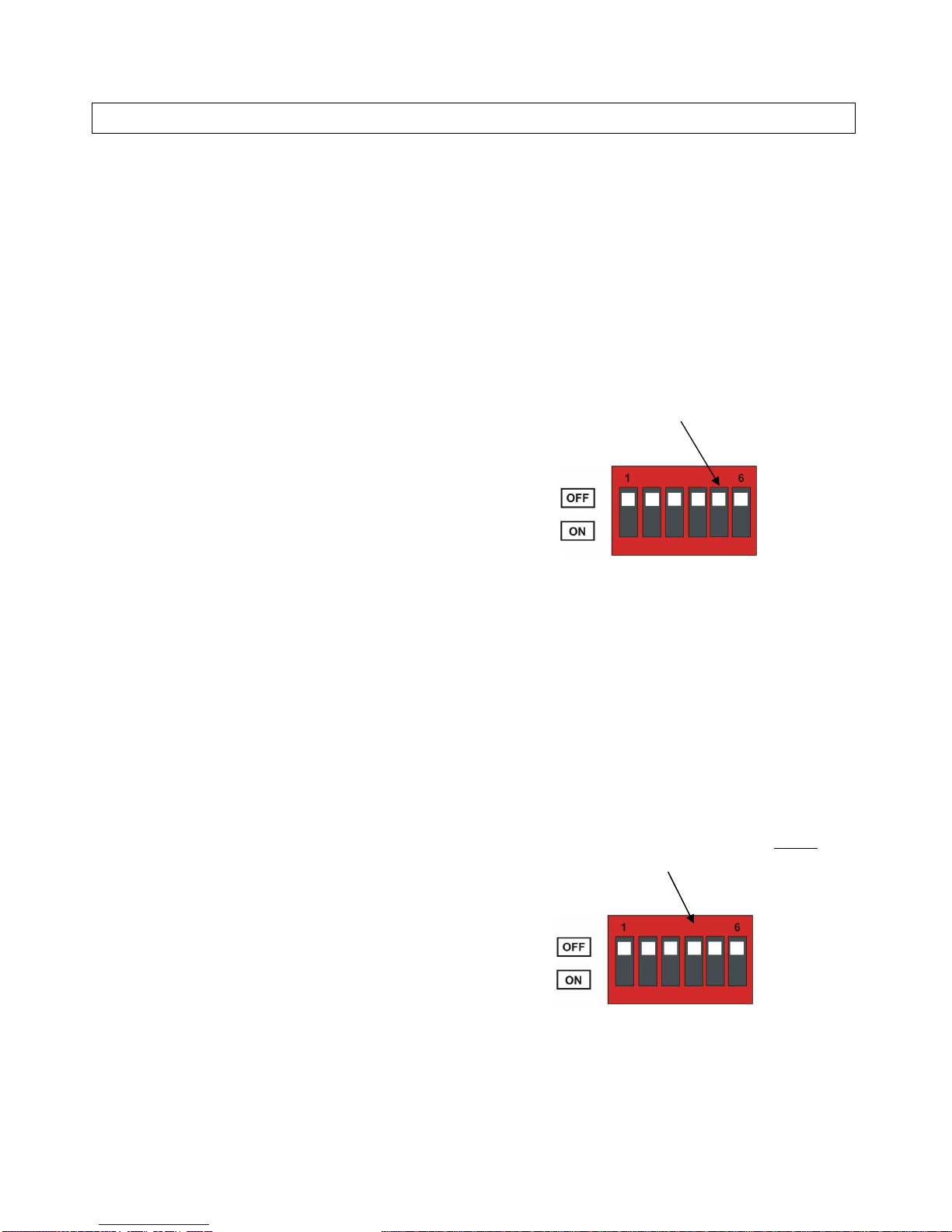
•Insert points bypass function at the front panel
•Signal switching by sealed gold contact relays
•True balanced architecture throughout the unit
•Ultra low noise and distortion
•+30 dBu microphone preamp input headroom
•Exceptionally open and transparent sound
•Input circuits have vacuum tube characteristics
•Smooth mic gain adjustment from +10 to +70 dB
by potentiometer, no clicks.
•Built-in +48 Volts Phantom Power
•Linear low noise power supply. No Switchmode!
•Slot for optional USB/AES/LAN digital interface.
•Inputs and outputs are ESD protected to 23 kV
IEC 61000-4-2 and 15 A surge IEC 61000-4-5.
•Sturdy steel metal casing, electrically and
magnetically screened.
•Stand-alone desktop or with mountable 19” rack
mount flanges
General description
Station 6 is an ultra low noise and ultra low distortion
mic/line preamplifier and monitor controller designed
with the professional sound engineer in mind.
Station 6 is constructed by using modern day's cutting
edge technology, but the basic design philosophy is
inspired by the very best sounding audio equipment that
have been manufactured over the past 50 years.
Station 6 uses the same highly acclaimed preamplifiers
as the LMA8 mic/line preamp, which gives the unit a
basic sound quality of extraordinary high class.
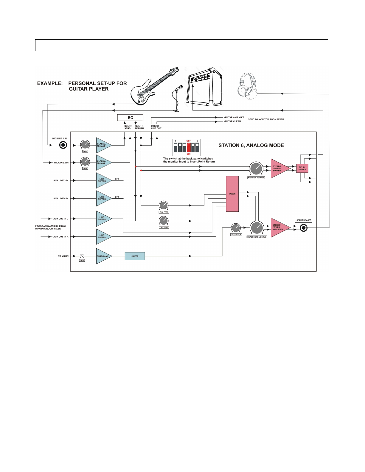
The unit is extremely versatile. It can operate in analog
mode as a personal audio center for the performing
artist, or it can operate in digital mode as a control center
for a recording studio or a video dubbing facility.
It has two high performance Class-A microphone/line
preamps, two auxiliary line inputs, two monitor line
outputs to speakers and a powerful headphone amplifier
with talk-back facility.
It also features zero latency feed forward controls from
the mic/line inputs to the headphones.
Two cue direct line inputs are available for zero latency
monitoring of external signals.
With the USB module installed, Station 6 communicates
with the DAW via USB full-speed. The USB connection
is compatible with USB 2.0, USB 3.0 and USB-C.
With the AES module installed, Station 6 communicates
with the DAW via a standard AES3 110 ohm transformer
balanced interface.
With the LAN module installed, Station 6 communicates
with the DAW via standard Gigabit Ethernet.
Station 6 features an unusual large input headroom on
all inputs, enabling it to handle fast transient and large
dynamic level changes. At the same time it reproduces
micro-details and environmental depth perspective with
a natural openness and an impressive accuracy.
The microphone input circuits are designed so input
clipping cannot be experienced. The input circuits have a
clipping limit (headroom) at +30 dBu, and because there
is always at least +10 dB of gain in the signal path, the
output (or the connected equipment) will simply always
clip before the input.
The line inputs also have +30 dBu clipping limit and
communicates with the DAW at the standard level of
+20 dBu as Digital Full Scale.
Again, under normal circumstances, input clipping
cannot be experienced.
Station 6 is a purist's dream come true. The design is
based on a very stringent philosophy, meaning the
shortest possible signal path and the highest possible
quality components. The microphone input circuit is a
true class A differential gain stage, and it has a transfer
characteristic that resembles that of a vacuum tube,
giving the unit a natural, relaxed and open sound, yet it
maintains high-speed and precise response.
The architecture is fully balanced throughout the unit,
which means that the signals between the various
circuits are routed as a positive and a negative signal,
not using ground to transfer audio signals at all.
This architecture keeps the audio path free from non-
linear distortion from currents running in the ground
mesh or from “non musical” signals from external
electrical fields, power supply noise, crosstalk from other
channels etc.
All signal routing and gain regulations are performed by
analog components. There are no digital switching and
no digital gain regulation to compromise the sound
quality. High grade conductive plastic potentiometers
and hermetically sealed relays with gold contacts are
used throughout the unit. No compromise!

Station 6 Preamplifier and Monitor Controller
4
Microphone, instrument and line inputs
The 2 microphone inputs are available at the 25 pin
D-SUB female connector on the back panel.
The gain is set by a potentiometer at the front panel
from +10 dB to +70 dB in one turn (no clicks!).
The +48 V Phantom Power is switched on/off at the front
panel. A Phantom Power block function is provided by
setting the DIP switch 3 at the back panel.
In the OFF position, Phantom Power is allowed.
In the ON position phantom power is blocked for both
microphone channels. The +48 V LED at the front will
flash briefly if switching on phantom power at the front is
attempted while the block function is ON.
The microphone inputs also work as line inputs.
The 6 kohm input impedance is perfect for line signals
(mind the phantom power though).
The 2 instrument inputs are available at the 1/4" Jack
connectors on the front panel.
They are direct inputs to the microphone preamplifier
and follows the gain setting at the front panel.
Plugging in a Jack connector automatically switches off
the microphone input at the back panel and changes the
input impedance to 1 Mohm, which is perfect for electric
guitars and electric bass. The input is equally well suited
for line level equipment, such as keyboards and the like.
An unusual feature of the instrument inputs is that they
are fully balanced. They work equally well with standard
unbalanced instrument cables as well as balanced
cables. However, using a balanced cable with result in a
substantial noise reduction.
This feature is highly advantageous on stages, and in
electrically noisy environments. (the cabling is described
in detail on page 20)
The 2 auxiliary line inputs are available at the 25 pin
D-SUB female connector on the back panel.
They have fixed gain, and are direct feeds to the DAW in
digital mode, and direct feeds to the monitor outputs in
analog mode.
The sensitivity is the standard + 20dBu for 0 dBFS and
the maximum input level is +30 dBu.
The 2 auxiliary cue inputs are available at the 25 pin
D-SUB female connector on the back panel.
They have fixed gain, and are direct feeds to the
cue/headphone outputs. The signal is mixed in hardware
with the cue signal from the DAW.
The sensitivity is the standard + 20dBu for 0 dBFS and
the max. input level is +30 dBu
The talk-back input is available at the back panel via a
3.5 mm mini jack connector. The input is intended for
dynamic microphones, but a +5 V phantom power for
electret or lavaliere microphones can be selected by
setting the DIP switch 1 at the back panel.
In the OFF position, no phantom power is provided.
In the ON position +5 V phantom power is provided.
The microphone input gain is set by a trim-potentiometer
at the back panel from +26 dB to +70 dB.

Station 6 Preamplifier and Monitor Controller
5
Insert points
The 2 microphone channels each have an analog insert
point available at the 25 pin D-SUB female connectors
on the back panel.
The direct output of the microphone channels is routed
to the insert send, and the insert return is routed
directly to the digital module and subsequently to the
DAW.
The insert point can be bypassed by pressing a switch at
the front panel.
The direct output from the mic channel is always
available at the insert send point, no matter whether the
insert point is bypassed or active.
There are two obvious advantages to having these
insert points:
It means that an old beloved analog compressor,
equalizer or similar can be inserted in the signal chain
between the microphone preamp output and the DAW.
It also means that the user has a direct line input to the
DAW via the insert return, when the insert point is
activated.
The insert points operate at standard level:
Insert send output is + 20dBu for 0 dBFS. Insert return
input is + 20dBu for 0 dBFS. Max input level is +30 dBu.
Direct outputs
The 2 direct outputs from the insert points are available
at the 25 pin D-SUB female connector on the back
panel.
The direct outputs are intended for external monitoring of
the inputs and outputs of the insert points.
There are two signal paths:
When the insert point is active, i.e. the inserted analog
equipment is inserted in the signal chain, the direct
output is sourced from the output of the equipment.
When the insert point is bypassed, i.e. the inserted
analog equipment is not inserted in the signal chain, the
direct output is sourced from the input of the equipment.
Monitor outputs
The monitor outputs (monitor L/R) are available at the
25 pin D-SUB female connector on the back panel.
The monitor outputs are intended for use with active
control room monitors.
Two different sets of monitors, SPKRS1 or SPKRS2, can
be selected by the pushbutton at the front panel.
The monitor outputs feature high performance balanced
floating industrial buffers, able to handle any impedance
from 600 ohm to infinite.
The nominal output level at 0 dBFS is selected by setting
the DIP switch 5 at the back panel.
OFF position is +8 dBu, ON position is +20 dBu.
The max output level is +28 dBu, which means that
under normal conditions, the buffers always have extra
headroom and thus no output clipping will occur.
3 signal paths of the monitor signals are possible:
1. In digital mode, the outputs are sourced from the
digital module (from the DAW) as default.
2. In analog mode the outputs are sourced directly from
the auxiliary line 3 and 4 inputs as default.
3. In both digital and analog mode, the outputs can be
switched to be sourced from the insert return points by
setting the DIP switch 4 at the back panel.
In the OFF position, the monitor outputs are sourced as
described above in point 1 and 2.
In the ON position, the monitor outputs are always
sourced from the insert return point
.

Station 6 Preamplifier and Monitor Controller
6
Cue headphone outputs
The cue outputs (headphone L/R) are available at two
1/4" Jack connectors, one at the front panel and one at
the back panel.
The outputs are intended for dynamic headphones and
features an unusual high output capability, able to drive
any impedance from 4 ohm to infinity. The outputs have
a maximum output swing of 45 V peak-peak and a
maximum output current of 1.2 Amp.
The headphone amplifier is protected against short
circuit and thermal overload. If the maximum current
draw is exceeded on either channel, both output signals
are muted for approx. 2 seconds after which they are
un-muted again.
No limiting or compression of the signals is used. When
the signals are present, they are clean and undistorted.
In order to avoid burning your headphones, two power
levels are available, selected by a switch at the front
panel.
LO is for the smaller in-ear headphones and for semi-pro
headphones typically with impedances ranging from 32
to 100 ohms.
HI is for professional headphones with impedances from
100 to 600 ohms.
Observe that these are only guidelines!
The meter can assist you. If you are on LO setting and
the RED clipping LEDs light up and you still feel the
need for more power, turn down the volume first, then go
to the HI setting.
Be careful! you don't want to burn your headphones (!)
The headphone amp is unusually powerful.
The cue/headphone outputs have 4 signal sources.
1. In digital mode, the signals are sourced from the
digital module (from the DAW). In analog mode, these
signals are disabled.
2. Direct feed from the microphone channels, controlled
by the volume potentiometers at the front panel.
3. Auxiliary cue inputs, available at the 25 pin D-SUB
female connector on the back panel. These input are
mixed directly into the signal path.
4. Talk-back signal from the microphone connected to
the 3.5 mm mini jack at the back. The signal is activated
by a pushbutton at the front and mixed into the
cue/headphone signals via its own volume control.

Station 6 Preamplifier and Monitor Controller
7
Digital Mode versus Analog Mode
Station 6 can operate in two modes, digital mode and
analog mode. The inputs and outputs are basically the
same in the two modes, but there are some notable
differences in the internal signal flow.
Digital mode:
Station 6 operates in digital mode as default when a
digital module is installed.
This mode is intended for a studio set-up with a DAW
with 4 channel recording and 4 channel monitoring.
Analog mode can be selected by setting DIP switch 6
at the back panel. When analog mode is selected, the
digital module goes into standby, and all clocks and
digital processing is halted.
In the OFF position, the unit operates in digital mode if a
digital module is present. If no digital module is present,
the unit automatically selects analog mode.
In the ON position, the unit enters analog mode and puts
any installed digital module in standby.
Analog mode:
When no digital module is installed, or if DIP switch 6 at
the back panel is set, Station 6 enters analog mode.
This mode is intended for the creative and technically
knowledgeable artist, technician or engineer.
In analog mode the digital module is disabled and the
A/D and D/A converters are bypassed, but all inputs and
outputs are still available.
The signal flow can be configured in lots of various
ways. Some examples are shown on the next pages, but
only the imagination sets the limits.

Station 6 Preamplifier and Monitor Controller
8
In the typical studio set-up with a DAW, the 4 signals from the inputs Mic1, Mic2, AUX Line3 and AUX Line4, are sent to
the A/D converter and subsequently to the DAW via the USB link.
The 4 output signals from the DAW are sent to the D/A converter via the USB link, and subsequently sent to the Monitor
and Cue(headphone) outputs. Channel 1 and 2 are sent to Monitor left and right, and channel 3 and 4 are sent to Cue left
and right.
Each of the inputs Mic1 and Mic2 have an Insert Point for use with analog equipment like Equalizers, compressors, filters,
what not. Note that the inserted analog equipment is placed in the signal chain before the A/D and the DAW.
The Line3 and Line3 signals are routed directly to the A/D and the DAW.
The Cue(headphone) outputs receive the signals from a local mixer, which has 4 input sources.
1. The main Cue outputs from the DAW and the D/A
2. The direct feeds from the microphone channels via potentiometers at the front, sourced from the Insert Point Returns.
3. The AUX Cue inputs Left and Right, straight into the mixer and to the Cue(headphones) output.
4. The Talk Back Input from the TB microphone input, controlled by the TB switch and volume potentiometer at the front.

Station 6 Preamplifier and Monitor Controller
9
When Station 6 is used with external A/D and D/A converters, it must operate in analog mode. There is no need to install
a digital module. With no digital module installed, the unit automatically enters analog mode.
If a digital module is installed, just set the DIP switch 6 to position ON. This will activate analog mode and deactivate the
digital module.
Inputs Mic1 and Mic2 are sent to the external A/D converter and to the DAW. Each of the inputs Mic1 and Mic2 have an
Insert Point for use with analog equipment like Equalizers, compressors, filters, what not. Note that the analog equipment
is placed in the signal chain before the external A/D and the DAW.
The monitor (master) outputs from the DAW and the external D/A are connected to the AUX Line 3 and AUX line 4 inputs
and directly routed to the Monitor Left and Right outputs.
The Cue outputs from the DAW and the external D/A are connected to the AUX Cue Left and Right inputs and routed, via
the mixer, to the Cue(headphones) Left and Right outputs.
The Cue(headphone) outputs receive the signals from a local mixer, which has 3 input sources.
1. The main Cue output from the DAW and the external D/A, via the AUX Cue Left and Right inputs
2. The direct feeds from the microphone channels via potentiometers at the front, sourced from the Insert Point Returns.
3. Talk Back Input from the TB microphone input, controlled by the TB switch and volume potentiometer at the front.

Station 6 Preamplifier and Monitor Controller
10
Above is an example showing Station 6 used as a personal center for the guitar player. The example is based on analog
mode, but it works equally well in digital mode.
If no digital module is installed, the unit automatically selects analog mode. If a digital module is installed, you can choose
between analog and digital mode by the DIP switch 6 at the back panel.
At a glance, the example seems complicated, but it is actually pretty much straight forward.
First, set DIP switch 3 to ON position. This will connect the monitor outputs Left and Right to the Insert Point Return. It
will also disconnect the Auxiliary Line 3 and 4 inputs in analog mode. (In digital mode the inputs are still connected to the
A/D)
The guitar is plugged into Mic1 Jack input (high-Z) at the front. The signal it then routed through the insert point to the
monitor left output, and to the direct output to the control room mixer. The monitor left output is then connected to the
guitar amp input.
The microphone in front of the guitar amp is connected to Mic2 input. The signal it then routed through the insert point to
the monitor left output, and to the direct line output to the control room mixer.
Program material from the control room mixer is sent to AUX Cue Left and Right input. The guitar player can then listen to
the program material from the monitor room, and mix the signals from the guitar direct/guitar-amp by the feed
potentiometers at the front.

Station 6 Preamplifier and Monitor Controller
11
Operational description
Quick guide, front and back controls and connections

Station 6 Preamplifier and Monitor Controller
12
Front panel
Instrument/line input
Each channel has a ¼" Jack instrument/line input on the
front panel. The input is for use with instruments (like
guitar, bass etc) and it can be used in a balanced as well
as an unbalanced configuration.
When a Jack is plugged-in, the input circuit automatically
de-activates the mic input at the back panel, switches to
high impedance mode and activates the line input.
Plugging in a mono Jack enables the normal unbalanced
input configuration.
Plugging in a stereo Jack enables the balanced input
configuration.
For further information about using the balanced
configuration see page 8, Remote ground connection
Insert point switch
The toggle switch controls the bypass function of the
insert point. The insert point exists electrically between
the output of the preamp and the input to the digital
module.
When the LED is ON, the signal chain between the
preamp and the digital module is “open” which means
that external equipment can be inserted between the
insert send and the insert return.
At the same time, the signal at the insert return point is
also sent to the direct line output.
When the LED is OFF, the signal is routed directly from
the preamp to the digital module. The insert return input
is then inactive.
At the same time, the signal from the insert send point
(preamp out) is also sent to the direct line output.
+48V Phantom Voltage
The toggle switch turns the Phantom Voltage at the mic
input on and off. The LED indicates the status.
When phantom voltage blocking is selected by setting
DIP switch 3, the +48V LED will flash briefly if you push
the button. No phantom voltage will be applied.

Station 6 Preamplifier and Monitor Controller
13
Input gain adjust
Turning the knob controls the input gain from minimum
to maximum in one smooth movement. No clicks and no
jumps. It works for both instrument/line input and
microphone input.
The gain range is +10 to +70 dB from input to the line
output on the D-SUB connector at the back.
Monitor volume control
Turning the knob controls the monitor output level from
minimum to maximum in one smooth movement. No
clicks and no jumps.
The output level range is from -80 dBu to +8 dBu,
(to + 20 dBu if DIP switch 5 is set)
Monitor speaker select
Two different sets of speaker sets can be connected.
The toggle switch controls which speaker set is active.
Only one speaker set at a time can be activated.
The switching is performed by relays with gold contacts,
and the levels at both outputs are identical.
Monitor mono/stereo switch
The toggle switch selects stereo or mono mode of the
monitor output.
When the LED lights up, mono mode is selected. No
light indicates stereo mode.
When switching between mono and stereo, odd phase
relationships in the signal can be revealed. The average
output level to the speakers remain unchanged.

Station 6 Preamplifier and Monitor Controller
14
Monitor and cue signal routing
A practical way of interchanging the monitor and cue
signals is available by two toggle switches.
In a studio set-up, the function comes in handy, when
the sound engineer wants to hear in the monitor
speakers what the artist hears in the headphones.
Or when the artist want to hear how the monitor mix
sounds in the headphones.
When pressing the Cue To Mon switch, the headphone
signal is sent to the monitor speakers. The cue signal in
the headphones is not affected. Pressing the switch
again brings back the monitor signal into the speakers.
When pressing the Mon To Cue switch, the monitor
signal is sent to the headphones. The monitor signal in
the speakers is not affected. Pressing the switch again
brings back the cue signal into the headphones.
Activating both functions at the same time will simply
swap the monitor and the cue signals.
A LED lights up when the corresponding routing
functions is activated. The NORM LED lights up when
none of the routing functions are activated.
Zero Latency Monitoring
Direct signal feed from the 2 microphone channels to the
headphones is provided. The signal are instantaneous
analog feed-forward and do not pass any switches or
digital circuitry.
The signals are mixed directly into the cue signal, and
the volume is controlled by two potentiometers at the
front. CH1FEED is sent to cue left and CH2FEED is sent
to cue right.
This means that a stereo recording from Mic1 and Mic2
can be sent directly to the headphones with zero latency.
In case only one mic channel is used, it would be quite
annoying to hear the signal only in one side of the
headphones. To get the signal in both sides, mono mode
can be selected by a toggle switch at the front.
Note that this switch do not reduce the left and right
signals to half level, like a standard mono function would
do to keep the sound impression at the same level.
Consider this switch as a standard routing function of the
signal, with no reduction of signal level. The signal goes
to one side or the signal goes to both sides.

Station 6 Preamplifier and Monitor Controller
15
Talk Back
The talk back function is controlled by a pushbutton and
a volume potentiometer at the front. The talk-back signal
is mixed directly into the cue signal.
The pushbutton is a standard momentary switch. Push it
and the talk back is active. Release it and the talk back
is muted.
However, if you push and release it quickly, within 0.5
second, it "sticks" and the talk-back is kept active. Push
it again and the talk-back is muted again.
A red LED lights up as a warning when the talk-back is
active.
Headphone output
The cue signal is sent to the headphone amplifier and
the output to headphones is sent to the 1/4" Jack at the
front panel and to the 1/4" Jack at the back panel.
The volume is controlled by the potentiometer and the
two level switch. The switch is a toggle switch, that
switches between high and low output level. The switch
has a 3 seconds delay in order to protect against
unintentional use.
The headphone amplifier is powerful. At high setting it is
able to give out 45 Volt peak to peak and a maximum
current of 1.2 Amp.
The high setting is for professional headphones. It will
easily burn semi-pro and budget headphones.
Hence a low setting is provided so you can use your in-
ear headphone from you mobile phone or use other low
wattage headphones from unknown origins.
The output is quite tolerant of abuse. It is protected
against short circuit or excessive current draw, and
allows wild an uncontrolled clipping and overdrive.
If the output meets unacceptable conditions, it will simply
mute for 2 seconds. When it opens up again, it first tests
the conditions before letting the audio through.
It never uses any kind of limiting to degrade the signal
quality. If the sound is there, it is pure and clean.
Meter
The meter is a 2x16 LED bar graph stereo peak meter
with fast attack and slow release
The pushbutton selects the input source to the meter:
There are 4 stereo sources available:
1: INP. The output of the input channels mic1 and mic2.
The signal is sourced at the insert send point.
2. DAW. The signal sent to the DAW. The signal is
sourced at the insert return point. When the insert point
is bypassed, the signals INP and DAW are identical.
When the insert point is active, INP and DAW are the
signals at the input and output of the external equipment.
3. MON. The signal sent to the monitor output,
measured after the volume control.
3. CUE. The signal sent to the headphones output
measured after the volume control.

Station 6 Preamplifier and Monitor Controller
16
Status indicators
The 4 status LEDs show the internal status of the unit.
1. SYNC. The LED lights up when the digital module is
locked and synchronized to an external word clock. If no
digital module is installed, or if analog mode is selected,
this indicator has no function.
2. COMM. The LED light up when a working handshake
link is established between the digital module and the
DAW. If no digital module is installed, or if analog mode
is selected, this indicator has no function.
3. DIGITAL. The LED lights up when the unit is operating
in digital mode.
4. ANALOG. The LED lights up when the unit is
operating in analog mode
Monitor dim during talk-back
The dim level of the monitor output signal, during talk-
back, can be programmed.
4 dim levels are available.0 dB, 6 dB, 12 dB or 18 dB.
Here is how:
1. Push and hold the Talk-Back button and the Meter
button simultaneously.
2. All these LEDs will light up to indicate that the unit is
in programming mode: HI, LO, SYNC, COMM, DIGITAL
and ANALOG.
3. The Meter source LEDs will now show the dim level.
From left to right, 0 dB, 6 dB, 12 dB or 18 dB.
Push the meter switch repeatedly to select the dim level
you want. You can freely push the TB button to test
while listening to the monitor.
4. When you are satisfied, push the headphone power
switch, and the unit returns to normal operation

Station 6 Preamplifier and Monitor Controller
17
Back panel
Mains input
The mains power inlet is a IEC 60320 receptacle for use
with a standard IEC 60320 C14 connector.
The acceptable voltage is 190 - 264 Volt AC, 50-60 Hz.
OBS: Always use the unit with safety earth.
Headphone output
The headphone amplifier output is sent to the 1/4" Jack
connector at the back panel and the 1/4" Jack connector
at the front panel.
The output signals at the two headphone Jacks, front
and back, are identical.
Talk Back input
The talk back microphone input can be found at the
3.5 mm stereo mini-jack at the back panel. The input is
balanced, and the input impedance is 1.2 kohm.
The input gain can be adjusted from +26 dB to +70 dB
by the trimmer potentiometer.
The TB mic input is mainly intended for dynamic
microphones, but a +5 V phantom voltage for electret or
lavaliere condenser microphones can be applied by
setting DIP switch 1.

Station 6 Preamplifier and Monitor Controller
18
Function switch summary
Switch 1:
Applies +5V Phantom voltage to the Talk Back mic input.
OFF position: No +5 V phantom voltage is applied. This
is for use of dynamic microphones.
ON position: +5 V phantom voltage is applied. This
setting is for use of lavaliere condenser microphones.
Switch 2: No function (optional future use)
Switch 3:
Controls +48V phantom voltage blocking. Default is OFF
OFF position: The use of +48 V phantom voltage at the
mic/line inputs is allowed.
ON position: The use of +48 V phantom voltage on the
mic/line inputs is blocked.
If you push the +48 V button at front anyway, the +48V
LED flashes briefly. No phantom voltage will be applied.
This is an essential safety feature to protect line
equipment, connected to the mic/line input, from
accidentally getting +48 V phantom voltage.
Switch 4
Controls monitor signal source. Default is OFF
OFF position: In digital mode, the signal to the monitor is
sourced from the DAW,
In analog mode, the signal to the monitor is sourced
from AUX line 3 and 4 inputs.
ON position: The signal to the monitor is always sourced
from the Insert Return Point, regardless of whether the
unit is in digital mode or in analog mode.
Switch 5
Controls monitor output level. Default is OFF.
OFF position: The signal level at the monitor output is
+8 dBu at 0 dBFS (digital full scale)
ON position: The signal level at the monitor output is
+20 dBu at 0 dBFS (digital full scale)
Switch 6
Controls digital or analog mode. Default is OFF.
OFF position: Selects digital mode when a digital module
is installed. If no digital module is installed, analog mode
is automatically selected.
ON position: Selects analog mode. Any installed digital
module is disabled and put into standby mode.

Station 6 Preamplifier and Monitor Controller
19
Analog outputs
The analog outputs can be found at the back panel at
the 25 pin female D-SUB connector.
The pin connections follow the Tascam Standard for
analog signals.
The list of signals and their corresponding pin
connections is listed below.
Analog inputs
The analog inputs can be found at the back panel at the
25 pin female D-SUB connector.
The pin connections follow the Tascam Standard for
analog signals.
The list of signals and their corresponding pin
connections is listed below.

Station 6 Preamplifier and Monitor Controller
20
Balanced cabling for instrument input
The balanced instrument/line input opens up the unique possibility to use a balanced configuration with instruments like
guitar, bass etc. The configuration will cancel out a large portion of the electrical noise induced in the cables. This is quite
advantageous when using long cables on stage or in an electrically noisy environment near light dimmers, high power
mains installations or nearby radio stations blasting megawatt into the air.
A guitar or bass hook-up is a high impedance system, and as such, it is very sensitive to electrical interference. Using a
balanced cable instead of a single core cable, introduces one additional wire to "receive" the environmental noise. This
additional noise signal is fed into the balanced input at the negative input terminal, canceling out the noise signal from the
positive terminal, all without affecting the sound signal from the instrument.
The configuration will in most cases give a substantial noise reduction, depending on the electrical characteristics of the
instrument pick-up. The negative and positive signal lines are terminated by different impedances at the instrument so a
total noise cancellation will not take place. The noise reduction is typically in the range of -15 dB to -20 dB.
Note that the noise from the instrument pick-ups is not reduced. Only the noise induced into the cable is reduced.
Table of contents
Other ROSTEC Amplifier manuals