36 MONTH/36,000 MILE LIMITED WARRANTY
Rostra Precision Controls, Inc. (the Company) warrants to the original retail purchaser of this product
that should this product or any part thereof, under normal use and conditions, be proven to have
defective material or workmanship within 36 months or 36,000 miles of the original purchase, such
defect(s) will be repaired or replaced (at the Company’s option) without charge for the parts. This
warranty does not apply to batteries or normal wear and tear associated with the Product.
To obtain repair or replacement with the terms of this Warranty, the product is to be delivered with
proof of warranty coverage (e.g. dated bill of sale), specification of defect(s), transportation prepaid, to
the installing dealer and/or retailer.
This Warranty does not cover costs incurred for the removal or reinstallation of the product, and/or
related components, and/or damage to the vehicle’s electrical system or components.
This Warranty does not apply to any product or part thereof which in the opinion of the Company has
been damaged through alteration, improper installation, misuse, neglect, accident, or customer abuse.
This Warranty is in lieu of all other express warranties or liabilities. ANY IMPLIED WARRANTIES,
INCLUDING ANY IMPLIED WARRANTY OF MERCHANTABILITY, SHALL BE LIMITED TO THE
DURATION OF THIS WRITTEN WARRANTY. ANY ACTION FOR BREACH OF ANY WARRANTY HERE-
UNDER INCLUDING ANY IMPLIED WARRANTY OF MERCHANTABILITY MUST BE BROUGHT WITHIN
A PERIOD OF 18 MONTHS FROM DATE OF ORIGINAL PURCHASE. IN NO CASE SHALL THE
COMPANY BE LIABLE FOR ANY CONSEQUENTIAL OR INCIDENTAL DAMAGES FOR BREACH OF
THIS OR ANY OTHER WARRANTY, EXPRESS OR IMPLIED, WHATSOEVER. No person or
representative is authorized to assume for the Company any liability other than expressed herein in
connection with the sale of this product.
THE EXTENT OF THE COMPANY’S LIABILITY UNDER THIS WARRANTY IS LIMITED TO THE REPAIR
OR REPLACEMENT PROVIDED ABOVE AND, IN NO EVENT, SHALL THE COMPANY’S LIABILITY
EXCEED THE PURCHASE PRICE PAID BY THE PURCHASER FOR THE PRODUCT.
Some states do not allow limitations on how long an implied warranty lasts or the exclusion or
limitation of incidental or consequential damage so the above limitations or exclusions may not apply
to you. This Warranty gives you specific legal rights and you may also have other rights which vary
from state to state.
ROSTRA PRECISION CONTROLS INC.
2519 Dana Drive * Laurinburg, NC 28352 * (910) 276-4853
OWNER’S WARRANTY RECORD
(To be completed by selling dealer and retained by customer)
Customer’s Name ________________________________________________________________
Address ________________________________________________________________________
Dealer Name ____________________________________________________________________
Dealer Address ___________________________________________________________________
City ____________________________________ State ____________ Zip ___________________
Date Purchased ________ Date Installed __________ Make & Year of Car __________________
Mileage at Installation ____________________________________________________________
The information in this manual has been carefully compiled through actual
vehicle testing and manufacturers service manual research and to the best of our
ability is accurate . However, we do not warrant the accuracy of this information
against changes in vehicle design, the use or misuse of this information or typograph-
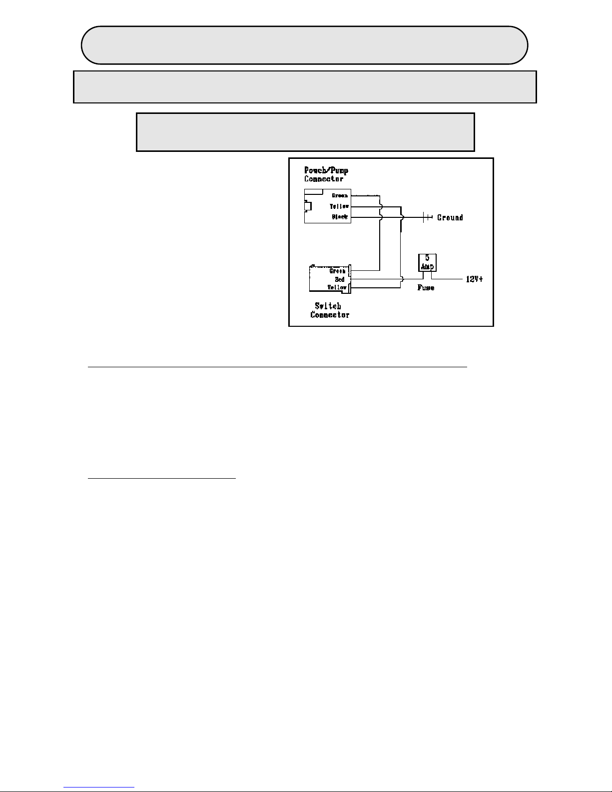
ical errors. It is the responsibility of the installer to verify the proper wire attachments
prior to and after the installation of the Lumbar System to assure proper operation.
We do not accept any responsibility for damage to the vehicle or injury to its occu-
pants caused by the use of this information. Improper installation and/or connection
to the incorrect wires could cause Lumbar System or vehicle malfunction, component
damage and/or personal injury for you and/or your passengers.
WARNING:
!