Rotary RWC1200 Leverless Pro Manual

O
P
E
R
A
T
I
O
N
&
M
A
I
N
T
E
N
A
N
C
E
M
A
N
U
A
L
© July 2021 by Vehicle Service Group. All rights reserved. CO11550.1
IMPORTANT Any damage caused by failure to follow the instructions in this manual or improper machine
use shall relieve the manufacturer of all liability.
O
P
E
R
A
T
I
O
N
&
M
A
I
N
T
E
N
A
N
C
E
M
A
N
U
A
L
RWC1200 Leverless Pro
7105-M012-01
Rev. n. 01 (07/2021)

SUMMARY
GENERAL DESCRIPTION __________________________ 3
SYMBOLS USED IN THE MANUAL __________________ 4
INFORMATION PLATE LOCATION DRAWING __________ 5
1.0 GENERAL INTRODUCTION ___________________ 7
1.1 Introduction __________________________________ 7
2.0 INTENDED USE ____________________________ 7
2.1 Training of personnel ___________________________ 7
3.0 SAFETY DEVICES___________________________ 8
3.1 Residual risks_________________________________ 8
4.0 IMPORTANT SAFETY INSTRUCTIONS __________ 9
4.1 General safety rules____________________________ 9
5.0 PACKING AND MOBILIZATION FOR TRANSPORT _ 10
6.0 UNPACKING _____________________________ 11
7.0 MOBILIZATION ___________________________ 11
8.0 WORKING ENVIRONMENT CONDITIONS _______ 12
8.1 Working position _____________________________ 12
8.2 Working area ________________________________ 12
8.3 Lighting ____________________________________ 12
9.0 MACHINE ASSEMBLY______________________ 13
9.1 Anchoring system ____________________________ 13
9.2 Assembly procedures _________________________ 14
9.3 Air connection _______________________________ 15
10.0 ELECTRICAL CONNECTIONS_________________ 16
10.1 Electrical checks _____________________________ 17
11.0 CONTROLS ______________________________ 17
11.1 Control unit _________________________________ 17
11.2 Control for bead breaking roller release ___________ 18
11.3 Bead pressing device operating unit ______________ 19
11.4 Pedalboard _________________________________ 19
12.0 USING THE MACHINE______________________ 20
12.1 Precaution measures during tire removal and fitting__ 20
12.2 Preliminary operations - Preparing the wheel _______ 20
12.3 Use of the lifting device ________________________ 20
12.4 Wheel clamping______________________________ 21
12.4.1 Rim blocking with tire down _________________ 23
12.4.2 Reverse wheel pan protection _______________ 23
12.5 Bead breaking operations ______________________ 24
12.6 Demounting the tire ___________________________ 25
12.7 Mounting the tire _____________________________ 28
12.7.1 Mounting the upper bead of the tire with the
bead pusher _____________________________ 29
12.8 Tire inflation with machine without tubeless inflation _ 30
12.9 Tire inflation with machine with tubeless inflation____ 30
12.10 Special use of the bead-breaker _________________ 31
13.0 ROUTINE MAINTENANCE___________________ 31
13.1 Rim arms calibration __________________________ 33
14.0 TROUBLESHOOTING TABLE _________________ 34
15.0 TECHNICAL DATA _________________________ 36
15.1 Technical electrical data _______________________ 36
15.2 Technical mechanical data _____________________ 36
15.3 Dimensions _________________________________ 37
16.0 STORING ________________________________ 38
17.0 SCRAPPING _____________________________ 38
18.0 REGISTRATION PLATE DATA_________________ 38
19.0 FUNCTIONAL DIAGRAMS ___________________ 38
Drawing A - Wiring diagram __________________________ 39
Drawing B - Pneumatic diagram _______________________ 43
2

GENERAL DESCRIPTION FIG. 1
13
18
17
2
3
14
7
8
9
5
15
16
12
1
10
6
11
19
4
20 21
KEY
1 - Chuck
2 - Tool
3 - Upper bead roller
4 - Lower bead roller
5 - Control unit / Storage box
6 - Pedal support
7 - Release push button for bead rollers horizontal and tool
movement
8 - Column unit
9 - Inflation pressure gauge unit
10 - Locking shaft unit
11 - Bead depressor with traction tool
12 - Tubeless inflation unit
13 - Rotating bead pressing device
14 - Lifting device
15 - Reverse wheels protection
16 - Two-faced cone
17 - Presser roller
18 - Bead pressing device operating unit
19 - Lateral lifting device
20 - Mounting grease
21 - Brush
3

SYMBOLS USED IN THE MANUAL
Symbols Description
Read instruction manual.
Wear work gloves.
Wear work shoes.
Wear safety goggles.
Mandatory. Operations or jobs to be per-
formed compulsorily.
Danger! Be particularly careful.
Symbols Description
Warning. Be particularly careful (possible
material damages).
Move with fork lift truck or pallet truck.
Lift from above.
Technical assistance necessary.
Do not perform any intervention.
Note. Indication and/or useful information.
4

INFORMATION PLATE LOCATION DRAWING
VSB1594000
VSB2166000
VSB2668000
VS999915200 VSB1541000
VSB2166000
VS999914700
VSB2170000
VSB2167000
VSB2168000
VSB1541000
VSB2166000
VS999924370
VS999924330
VSB4221000
VSB4244000 VS99990758
VS710211210
VSB3691000
VSB2166000
VSB1541000
VS999916450
VSB1541000
VS99990758
VSB1541000
VSB4244000
VS999916880
VSB1541000
VS999916311
VS999924390
VS999930150
VS999923400
VS999923160
VS999923300
VS999922390
VS999923350
VS999923360
VS999915200
VSB4221000
5

VSB1541000 Danger plate
VSB1594000 Date indicating plate
VSB2166000 Bead breaker danger plate
VSB2167000 Protective clothing plate
VSB2168000 Tire burst plate
VSB2170000 Max inflation pressure rating plate
VSB2668000 Wheel lifting device danger plate
VSB3691000 Inflation pedal plate
VSB4221000 Grounding plate
VSB4244000 Rotating parts danger plate
VS710211210 Rotation direction plate
VS99990758 Electricity danger plate
VS999914700 Bead depressing roller controls plate
VS999915200 Serial number plate
VS999916311 Rubbish skip plate
VS999916450 Lifting device pedal plate
VS999916880 Max. capacity load 80 Kg plate (176 lbs)
VS999930150 Rotary plate
VS999922390 Overload protection plate
VS999923160 Prop 65 Attention plate
VS999923300 1Ph 220V 20A 60 Hz voltage plate
VS999923350 For indoor use plate only
VS999923360 Disconnect power supply plate
VS999923400 UL-CSA ready plate
VS999924330 Up/down tool carriage plate
VS999924370 Up/down bead rollers plate
VS999924390 Rotary plate
IF ONE OR MORE PLATES DISAPPEAR FROM THE MACHINE OR BECOMES DIFFICULT TO READ. REPLACE IT AND QUOTE
ITS/THEIR CODE NUMBER/S WHEN REORDERING.
6

SOME OF THE PICTURES PRESENT IN THIS MAN-
UAL HAVE BEEN OBTAINED FROM PICTURES
OF PROTOTYPES, THEREFORE THE STANDARD
PRODUCTION MACHINES AND ACCESSORIES
CAN BE DIFFERENT IN SOME COMPONENTS.
1.0 GENERAL INTRODUCTION
This manual is an integral part of the product and must be retained
for the whole operating life of the machine.
Carefully study the warnings and instructions contained in this
manual. It contains important instructions regarding functioning,
SAFE USE and MAINTENANCE.
KEEP THE MANUAL IN A KNOWN, EASILY AC-
CESSIBLE PLACE FOR ALL ACCESSORY OPERA-
TORS TO CONSULT IT WHENEVER IN DOUBT.
THE MANUFACTURER DISCLAIMS ALL RESPON-
SIBILITY FOR ANY DAMAGE OCCURRED WHEN
THE INDICATIONS GIVEN IN THIS MANUAL ARE
NOT RESPECTED: AS A MATTER OF FACT, THE
NON-COMPLIANCE WITH SUCH INDICATIONS
MIGHT LEAD TO EVEN SERIOUS DANGERS.
1.1 Introduction
Thank you for purchasing electro-hydraulic tire-changer. We feel
sure you will not regret your decision. The machine has been de-
signed for use in professional workshops and in particular it stands
out for its reliability, safe and rapid operation: with just a small
degree of maintenance and care, this will give you many years of
trouble-free service and lots of satisfaction. This manual contains
all operating instructions and details on how to service and use the
machine correctly.
2.0 INTENDED USE
The machines described in this manual and their different
versions, are tire-changers for car tire projected to be used
exclusively for the mounting, demounting, and inflation of wheels
with dimension and width values mentioned in “Technical speci-
fications” chapter.
THIS MACHINE MUST BE USED STRICTLY FOR
THE INTENDED PURPOSE IT WAS DESIGNED
FOR (AS INDICATED IN THIS MANUAL).
THE MANUFACTURER CANNOT BE HELD RE-
SPONSIBLE FOR ANY DAMAGE CAUSED BY IM-
PROPER, ERRONEOUS, OR UNACCEPTABLE USE.
2.1 Training of personnel
The machine may be operated only by suitably trained and author-
ized personnel.
Given the complexity of the operations necessary to manage the
machine and to carry out the operations safely and efficiently, the
personnel must be trained in such a way that they learn all the
information necessary to operate the machine as intended by the
manufacturer.
A CAREFUL READING OF THIS INSTRUCTION
MANUAL FOR USE AND MAINTENANCE AND
A SHORT PERIOD OF TRAINING WITH SKILLED
PERSONNEL CAN BE ENOUGH PREVENTIVE
PREPARATION.
7

• Additionalsafetydeviceforprotectionagainstfuseexcesscurrent
(see figure below).
3.1 Residual risks
The machine was subjected to a complete analysis of risks accord-
ing to reference standard EN ISO 12100.
Risks are as reduced as possible in relation with technology and
product functionality.
This manual stresses possible residual risks, also highlighted in
pictograms on the present manual and adhesive warning signals
placed on the machine: their location is represented in “PLATE
LOCATION ON MACHINE INFORMATION DRAWING” on page 5.
3.0 SAFETY DEVICES
DAILY CHECK THE INTEGRITY AND THE FUNC-
TIONALITY OF THE SAFETY AND PROTECTION
DEVICES ON THE MACHINE.
All the machines are equipped with:
• “man-operated”controls(immediatestopofoperationwhenthe
control is released) for all operating devices;
• chuckrotation;
• toolmovement;
• beadbreakingrollermovement.
• Logicdispositionofcontrols.
Its function is to prevent the operator from dangerous mistakes.
• Fixedprotectionsandguards
The machine is fitted with a number of fixed guards intended to
prevent potential crushing, cutting and compression risks.
These protections have been realized after risks evaluation and
after all machine operative situations have been considered.
All protections, specially the rubber ones, have to be periodically
checked in order to evaluate their wear state.
PERIODICALLY, AT LEAST MONTHLY, CHECK
THE INTEGRITY AND THE FUNCTIONALITY OF
THE SAFETY AND PROTECTION DEVICES ON
THE MACHINE.
• Non-adjustable(balancing valve)pressure relief device.
This allows inflation of tires in reasonable safety. Inflation of tires
to over 4.2 ± 0.2 bar (60 ± 3 psi) is not allowed.
8

4.1 General safety rules
• Anytamperingwithor modication tothemachinenot previ-
ously authorized by the manufacturer exempts the latter from all
responsibility for damage caused by or derived from said actions.
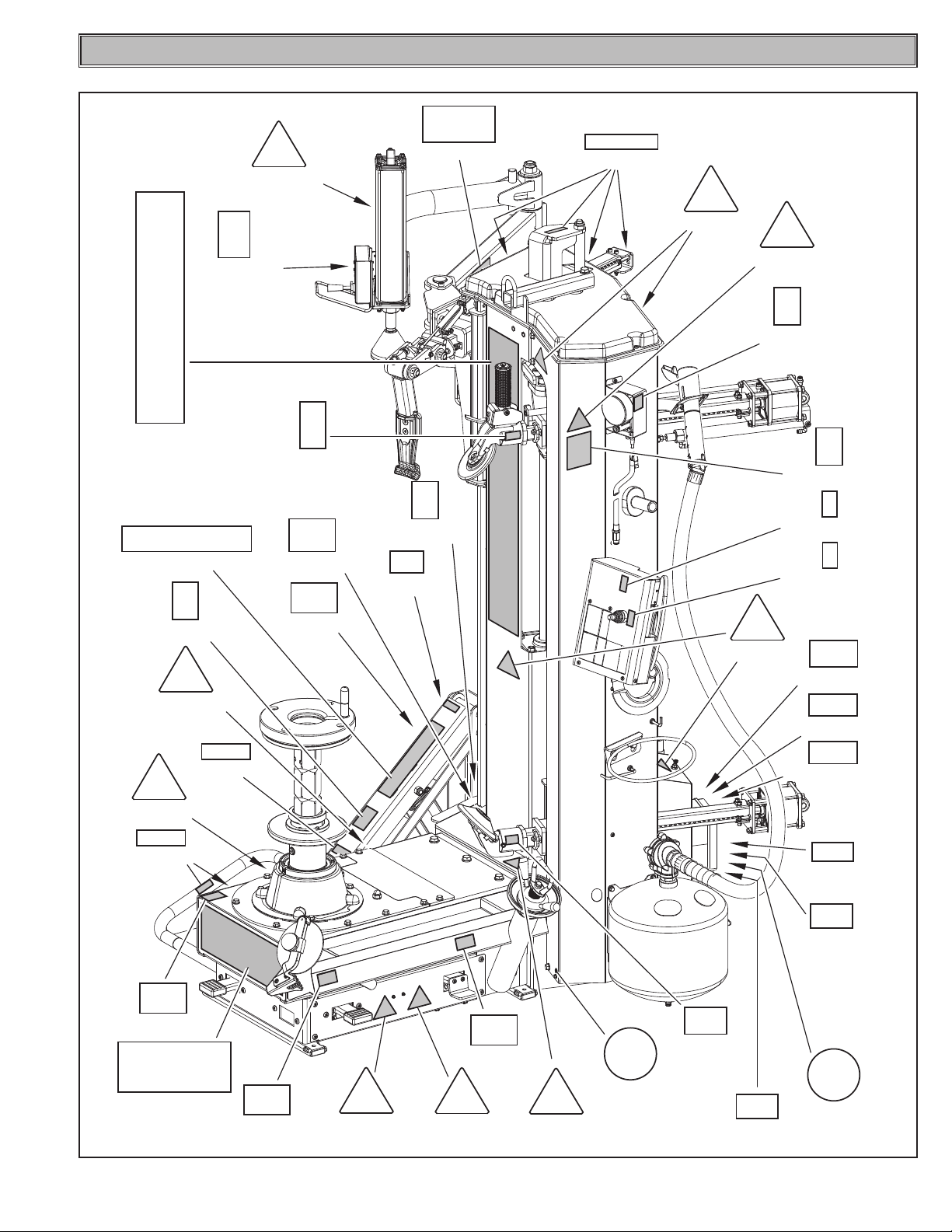
• Removingofortampering with thesafetydevicesorwith the
warning signals placed on the machine leads to serious dangers
and represents a transgression of OSHA safety standards.
• Useofthemachineisonlypermittedinplacesfreefromexplosion
or fire hazard and in dry places under cover.
• Originalsparepartsandaccessoriesshouldbeused.
THE MANUFACTURER DENIES ANY RESPON-
SIBILITY IN CASE OF DAMAGES CAUSED BY
UNAUTHORIZED MODIFICATIONS OR BY THE
USE OF NON ORIGINAL COMPONENTS OR
EQUIPMENT.
• Theinstallationmustbeperformedbyqualiedandauthorized
personnel in full compliance with the instructions given below.
• Ensurethattherearenodangeroussituationsduringthemachine
operating manoeuvres. Immediately stop the machine if it miss-
functions and contact the customer service of an authorized
dealer.
• Inemergencysituationsandbeforecarryingoutanymaintenance
or repairs, disconnect all supplies to the machine by using the
main switch.
• Themachinepowersupplysystemmustbeequippedwithanap-
propriate earthing, to which the yellow-green machine protection
wire must be connected.
• Ensurethattheworkareaaroundthemachineisfreeofpotentially
dangerous objects and that there is no oil since this could damage
the tire. Oil on the floor is also a potential danger for the operator.
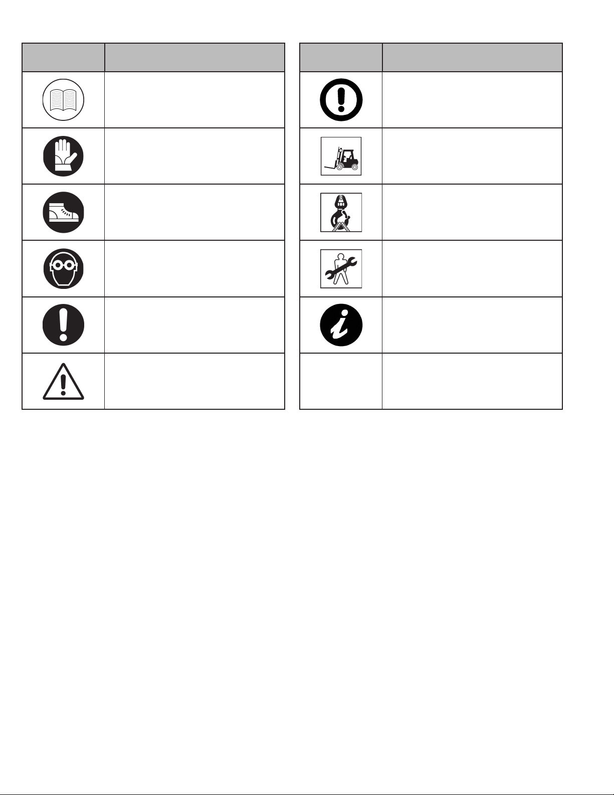
OPERATORS MUST WEAR SUITABLE WORK
CLOTHES, PROTECTIVE GLASSES AND GLOVES,
AGAINST THE DANGER FROM THE SPRAYING
OF DANGEROUS DUST, AND POSSIBLY LOWER
BACK SUPPORTS FOR THE LIFTING OF HEAVY
PARTS. DANGLING OBJECTS LIKE BRACELETS
MUST NOT BE WORN, AND LONG HAIR MUST
BE TIED UP. FOOTWEAR SHOULD BE ADEQUATE
FOR THE TYPE OF OPERATIONS TO BE CAR-
RIED OUT.
4.0 IMPORTANT SAFETY INSTRUCTIONS
When using your garage equipment, basic safety precautions should
always be followed, including the following:
1. Read all instructions.
2. Care must be taken as burns can occur from touching hot parts.
3. Do not operate equipment with a damaged cord or if the equip-
ment has been dropped or damaged – until it has been examined
by a qualified service person.
4. Do not let a cord hang over the edge of the table, bench, or
counter or come in contact with hot manifolds or moving fan
blades.
5. If an extension cord is necessary, a cord with a current rating
equal to or more than that of the equipment should be used.
Cords rated for less current than the equipment may overheat.
Care should be taken to arrange the cord so that it will not be
tripped over or pulled.
6. Always unplug equipment from electrical outlet when not in use.
Never use the cord to pull the plug from the outlet. Grasp plug
and pull to disconnect.
7. Let equipment cool completely before putting away. Loop cord
loosely around equipment when storing.
8. To reduce the risk of fire, do not operate equipment in the vicinity
of open containers of flammable liquids (gasoline).
9. Adequate ventilation should be provided when working on
operating internal combustion engines.
10. Keep hair, loose clothing, fingers, and all parts of body away
from moving parts.
11. To reduce the risk of electric shock, do not use on wet surfaces
or expose to rain.
12. Use only as described in this manual. Use only manufacturer’s
recommended attachments.
13. ALWAYS WEAR SAFETY GLASSES. Everyday eyeglasses only
have impact resistant lenses, they are not safety glasses.
SAVE THESE INSTRUCTIONS
9

• Themachinehandlesandoperatinggripsmustbekeptcleanand
free from oil.
• Theworkshopmustbekeptcleananddry.Makesurethatthe
working premises are properly lit.
The machine can be operated by a single operator. Unauthor-
ized personnel must remain outside the working area, as shown
in Fig. 4.
Avoid any hazardous situations. Do not use air-operated or elec-
trical equipment when the shop is damp or the floor slippery and
do not expose such tools to atmospheric agents.
• Duringinationdonotleanonthetireorstandonit;whenbeading
in the tire, keep hands away from tire and rim edge.
• Duringinationalwaysstaytothesideofthemachineandnever
in front of it.
• Whenoperatingandservicingthismachine,carefullyfollowall
applicable safety and accident-prevention precautions.
The machine must not be operated by untrained personnel.
•Neveractivatetheinationdevice(onlyonmodelswithtubeless
inflation) if the tire has not been correctly locked.
IN CASE OF A CHANCE SUPPLY FAILURE
(WHETHER ELECTRICITY OR COMPRESSED
AIR), MOVE THE PEDALS TO THE NEUTRAL
POSITION.
5.0 PACKING AND MOBILIZATION FOR TRANSPORT
HAVE THE MACHINE HANDLED BY SKILLED PERSONNEL ONLY.
THE LIFTING EQUIPMENT MUST WITHSTAND A MINIMUM
RATED LOAD EQUAL TO THE WEIGHT OF THE PACKED MACHINE
(see paragraph “TECHNICAL SPECIFICATIONS”).
The machine is packed partially assembled.
Handling must be by pallet-lift or fork-lift trolley.
The fork lifting points are indicated on the packing.
Fig. 2
10

7.0 MOBILIZATION
THE LIFTING EQUIPMENT MUST WITHSTAND A MINIMUM
RATED LOAD EQUAL TO THE WEIGHT OF THE MACHINE (SEE
PARAGRAPH TECHNICAL SPECIFICATIONS). DO NOT ALLOW
THE LIFTED MACHINE TO SWING.
During the machine handling from the unpacking position to the
installation one, follow the instructions listed below.
• Protecttheexposed corners with suitablematerial(Pluribol/
cardboard).
• Donotusemetalliccablesforlifting.
• Makesurethatthepowersupplyisnotconnected.
• Liftandtransportwithsuitabledevicewithadequatedimensions,
as indicated in Fig._3.
Fig. 3
6.0 UNPACKING
DURING UNPACKING, ALWAYS WEAR GLOVES
TO PREVENT ANY INJURY CAUSED BY CON-
TACT WITH PACKAGING MATERIAL (NAILS,
ETC.).
The cardboard box is supported with plastic strapping. Cut the
strapping with suitable scissors. Use a small knife to cut along the
lateral axis of the box and open it like a fan.
It is also possible to unnail the cardboard box from the pallet it is
fixed to. After removing the packing, and in the case of the machine
packed fully assembled, check that the machine is complete and
that there is no visible damage.
If in doubt do not use the machine and refer to professionally quali-
fied personnel (to the seller).
The packing (plastic bags, expanded polystyrene, nails, bolts, timber,
etc.) should not be left within reach of children since it is potentially
dangerous. These materials should be deposited in the relevant
collection points if they are pollutants or non biodegradable.
THE BOX CONTAINING THE FIXTURES IS CON-
TAINED IN THE WRAPPING. DO NOT THROW
IT AWAY WITH THE PACKING.
11

8.0 WORKING ENVIRONMENT CONDITIONS
The machine must be operated under proper conditions as follows:
• temperature:+5°C+40°C(+41°F÷+104°F)
• relativehumidity:30-95%(dew-free)
• atmosphericpressure:860-1060hPa(mbar)(12.5÷15.4psi).
The use of the machine in ambient conditions other than those
specified above is only allowed after prior agreement with and ap-
proval of the manufacturer.
8.1 Working position
In Figure 4 it's possible to define work positions A and B which will be
referred to during the description of the machine operating phases.
Position A is the main position for wheel fitting and removal with the
chuck, while position B is ideal to follow tire inflation operations.
Working in these positions allows better precision and speed during
operating phases as well as greater safety for the operator.
8.2 Working area
Fig. 4
A
B
~ 1000 mm
~ 39.37"
~ 1000 mm
~ 39.37"
~ 1000 mm
~ 39.37"
USE THE MACHINE IN A DRY AND ADEQUATELY LIT PLACE,
POSSIBLY INDOORS OR IN A ROOFED AREA, THIS PLACE MUST
BE IN COMPLIANCE WITH APPLICABLE SAFETY REGULATIONS.
The location of the machine requires a usable space as indicated
in Figure 4. The positioning of the machine must be according to
the distances shown. From the control position the operator is able
to observe all the machine and surrounding area. He must prevent
unauthorized personnel or objects that could be dangerous from
entering the area. The machine must be secured on a flat floor
surface, preferably of cement or tiled. Avoid yielding or irregular
surfaces. The base floor must be able to support the loads transmit-
ted during operation. This surface must have a capacity load of at
least 500 Kg\m² (102 lb/ft2).
The depth of the solid floor must be sufficient to guarantee that the
anchoring bolts hold.
8.3 Lighting
The machine does not require its own lighting for normal working op-
erations. However, it must be used in an adequately lit environment.
12

9.0 MACHINE ASSEMBLY
EACH MECHANICAL INTERVENTION MUST BE
CARRIED OUT BY PROFESSIONALLY QUALIFIED
STAFF.
After having freed the various components from the packing check
that they are complete, and that there are no anomalies, then comply
with the following instructions for the assembly of the components
making use of the attached series of illustrations.
9.1 Anchoring system
The packed machine is secured to the support pallet through the
holes prearranged on the frame. Such holes can be used also
to secure the machine to the ground, through floor anchor small
blocks (excluded from supply). Before carrying out the definitive
fastening, check that all the anchor points are laid down flat and
correctly in contact with the fixing surface itself. If not so, insert
shimming profiles between the machine and the fixing lower surface,
as indicated in Fig. 5.
Fig. 5
a = 651 mm / 25.63”
b = 440 mm / 17.32”
• Execute4holeswith12mmdiameterontheoorbytheholeson
the bottom floor;
• insertthesmallblocks(excludedfromsupply)intotheholes;
• securethemachinetothegroundwith4M12x120mmbolts(ex-
cluded from supply) (Fig. 5 ref. 1) (or with 4 12x80 mm stud bolts
(excluded from supply)). Tighten the bolts with an approximate
tightening torque of 70 Nm (52 ft•lbs).
• Beforeclampingcompletelythemachinetotheoor,levelitsrear
part rotating the feet (Fig. 6 ref. 1).
Fig. 6
1
13

3. Fit the grease holder ring (Fig._9 ref._1) with the 2 supplied bolts
(Fig._9 ref._2), to the threaded inserts provided on the machine
(Fig._9 ref._3), as shown in Fig._9.
Fig. 9
4. Mount the side tray (Fig._10 ref._1) to the machine frame using
the supplied bolts (Fig._10 ref._2), as shown in Fig._10.
Fig. 10
12
2
5. Remove the handle control unit (Fig._11 ref._1), complete with
support (Fig._11 ref._2), from the bracket (Fig._11 ref._3). Remove
the bracket (Fig._11 ref._3) from the machine frame and remove
it upwards. Reassemble the manipulator unit (Fig._11 ref._1) on
the machine frame by manually accompanying the set of cables/
pipes (Fig._11 ref._6) inside the prepared opening, as indicated
in Fig._11.
PLACE THE SET OF CABLES/PIPES (Fig. 11
ref. 6) INSIDE THE MACHINE BRINGING THE
EXCESS LENGTH DOWNWARDS.
9.2 Assembly procedures
1. Fit the tank (Fig._7 ref._1) of the Tubeless inflation unit by tighten-
ing the supplied bolts (Fig._7 ref._2) to the threaded inserts on
the machine (Fig._7 ref._3), as shown in Fig._7.
Fig. 7
2. Connect the black pipe (Fig._8 ref._1) and the blue pipe (Fig._8
ref._2) on the provided quick couplings as shown in figure Fig._8.
Fig. 8
14

Secure the handle unit (Fig._11 ref._1) with the bolts (Fig._11
ref._4) to the threaded inserts on the machine (Fig._11 ref._5).
THE CABLES/PIPES (Fig. 11 ref. 6) MUST
NEVER COME INTO CONTACT WITH THE BEAD
BREAKERS CARRIAGES.
MAKE SURE TO CORRECTLY SECURE THE SET
OF CABLES/PIPES TO THE FRAME USING THE
PROVIDED FASTENERS.
Fig. 11
6. Fit the wheel support (Fig._12 ref._1) to the lift frame (Fig._12
ref._2) using the bolts (Fig._12 ref._3), washers (Fig._12 ref._4),
nuts (Fig._12 ref._5) placing the spacers between the support
and the frame (Fig._12 ref._6).
1
2
3
4
4
5
6
6
Fig. 12
9.3 Air connection
ANY PNEUMATIC INTERVENTION MUST BE
CARRIED OUT BY PROFESSIONALLY QUALI-
FIED STAFF.
Connect the mains pneumatic supply through the fitting (Fig._13
ref._1) placed on the machine filter unit. The pressurized pipe
(Fig._13 ref._2) coming from the mains must have a section of 10x19
(see Fig.13).
Fig. 13
IF OTHER PNEUMATIC CONNECTIONS SHOULD
BE EXECUTED, REFER TO THE PNEUMATIC DIA-
GRAMS ILLUSTRATED IN CHAPTER 19.
IN CASE OF A CHANCE SUPPLY FAILURE, AND/
OR BEFORE ANY PNEUMATIC CONNECTIONS,
MOVE THE CONTROLS TO THE NEUTRAL PO-
SITION.
15

10.0 ELECTRICAL CONNECTIONS
EVEN THE TINIEST PROCEDURE OF AN ELEC-
TRICAL NATURE MUST BE CARRIED OUT BY
PROFESSIONALLY QUALIFIED STAFF.
BEFORE CONNECTING THE MACHINE MAKE
SURE THAT:
• POWER LINESPECIFICATIONSCORRE-
SPOND TO MACHINE REQUIREMENTS AS
SHOWN ON THE MACHINE PLATE;
• ALLMAINPOWERCOMPONENTSARE IN
GOOD CONDITION;
• THEELECTRICALSYSTEM IS PROPERLY
GROUNDED (GROUND WIRE MUST BE THE
SAME CROSS-SECTION AREA AS THE LARG-
EST POWER SUPPLY CABLES OR GREATER);
• MAKESURETHATTHEELECTRICALSYSTEM
FEATURES A CUTOUT WITH DIFFERENTIAL
PROTECTION SET AT 30 MA.
As envisaged by the regulations in force, the machine is not
equipped with a master circuit breaker, but simply has a plug-socket
connection to the electrical mains.
The machine is supplied with a cable. A plug corresponding to the
following requirements must be connected to the cable:
FIT A TYPE-APPROVED PLUG TO THE MACHINE
CABLE (THE GROUND WIRE IS YELLOW/GREEN
AND MUST NEVER BE CONNECTED TO ONE OF
THE PHASE LEADS).
MAKE SURE THAT THE ELECTRICAL SYSTEM
IS COMPATIBLE WITH THE RATED POWER AB-
SORPTION SPECIFIED IN THIS MANUAL AND
APT TO ENSURE THAT VOLTAGE DROP UNDER
FULLLOADWILLNOTEXCEED4%OFRATED
VOLTAGE(10%UPONSTART-UP).
IN CASE OF A CHANCE SUPPLY FAILURE, AND/
OR BEFORE ANY POWER SUPPLY CONNEC-
TIONS, MOVE THE PEDALS TO THE NEUTRAL
POSITION.
Models Type Voltage Amperage Poles Minimum IP
rating
Inverter NEMA L6-20P 200/265V 16A 2Poles+Ground IP 44
16

10.1 Electrical checks
BEFORE STARTING UP THE TIRE-CHANGER, BE
SURE TO BECOME FAMILIAR WITH THE LOCA-
TION AND OPERATION OF ALL CONTROLS AND
CHECK THEIR PROPER OPERATION (SEE PAR.
“CONTROLS”).
CARRY OUT A DAILY CHECK OF MAINTAINED-
TYPE CONTROLS CORRECT FUNCTIONING,
BEFORE STARTING MACHINE OPERATION.
11.0 CONTROLS
11.1 Control unit
It consists of two levers (Fig. 14 ref. A) and of two push buttons
(Fig. 14 ref. B) and a lever (Fig. 14 ref. C), with different functions,
fit onto a single control block.
The control unit can be used to move the upper and lower bead-
breakers and the tool and place them in the working position.
The control unit therefore governs all the movements necessary for
a complete bead-breaking, assembly and disassembly operation:
•
bead rollers vertical shift movement.
•
introduction of the bead breaker rollers inside the rim,
•
mounting tool vertical shift movement.
The upper lever and button (A-B (UPP)) control the upper bead
breaker roller, vice versa the lower lever and button (A-B (LOW))
control the lower bead breaker roller.
Each lever has three positions:
- the first one (Fig. 14 ref. 1) is rest position, that keeps the bead
rollers into their current position.
- the second one (Fig. 14 ref. 2) (pressed lever, maintained-type
control) operates upper bead breaker roller descent (UPP. lever)
and/or lower bead breaker roller rise (LOW. lever).
- the third one (Fig. 14 ref. 3) (lever’s lifting) operates upper bead
breaker roller’s rise (UPP. lever) and/or lower bead breaker roller’s
descent (LOW. lever).
Pressing UPP. or LOW. maintained-type push buttons (Fig. 14
ref. B), the corresponding cam introduces the bead breaker roller
into the rim.
The control unit is also equipped with the lever (Fig. 14 ref. C) which
controls the ascent and descent of the tool:
- lift the lever to move the tool upwards;
- lower the lever to move the tool downwards.
17

Fig. 14
A (UPP)
A
(LOW)
B
(LOW)
B (UPP)
C
C
2
1
3
A
11.2 Control for bead breaking roller release
This is done completely manually. Press the release push button
(Fig. 15 ref. 1), then operate the handle (Fig. 15 ref. 2), for the
manual positioning of the upper and lower bead rollers and the tool
on the correct diameter of the wheel fixed onto the chuck, through a
concurrent lever’s thrust and return movement. Releasing the push
button, the rollers lock into their current position.
The cylinder (Fig. 15 ref. 3) makes the entire operation described
above easier. The cylinder is activated when, after pressing the
button (Fig. 15 ref. 1), a slight pulling or pushing movement of the
knob is performed (Fig. 15 ref. 2). The intervention force of the
cylinder can be adjusted (Fig. 15 ref. 3) by acting on the regulator
(Fig. 15 ref. 4), located on the solenoid valve protection casing
(Fig. 15 ref. 5).
Fig. 15
18

11.3 Bead pressing device operating unit
It is made up of an handle control (Fig. 16 ref. 1), positioned on the
device. This handle control allows to operate the vertical movement
of the presser roller (Fig. 16 ref. 3). Lift the lever (Fig. 16 ref. 2) to
operate the upwards movement, and lower the lever (Fig. 16 ref. 2)
to perform the downwards movement. The device arm positioning
next to the tire is a completely manual operation.
Fig. 16
11.4 Pedalboard
“Pedal A” has two maintained action operative positions. When
it is pushed downwards it controls chuck motor clockwise rotary
movement. When the pedal is lifted upwards it operates the op-
posite movement.
THE CHUCK UNIT SPEED CAN BE CONTINU-
OUSLY ADJUSTED UP TO THE MAXIMUM
SPEED THROUGH A PROGRESSIVE PRESSURE
ON THE PEDAL, ONLY IN CLOCKWISE DIREC-
TION.
“Pedal B” has a different function according to the version present
on the machine.
Version with inflation with pressure gauge
The inflation pedal in this version has only one function. A continu-
ous pressure supplies air at a controlled pressure (max 4.2 ± 0.2
bar / 60 ± 3 psi).
DO NOT CHANGE THE SET OPERATING PRES-
SURE VALUE BY MEANS OF THE MAXIMUM
PRESSURE VALVES. THE MANUFACTURER
SHALL NOT BE RESPONSIBLE FOR INJURY
OR DAMAGE ARISING FROM UNAUTHORISED
CHANGES.
Version with tubeless inflation
The inflation pedal has two functions. The supply of air at max. con-
trolled pressure as in the previous version, and a second function of
a jet of air from the inflation nozzle to assist the beading in of the tire.
DO NOT CHANGE THE SET OPERATING PRES-
SURE VALUE BY MEANS OF THE MAXIMUM
PRESSURE VALVES. THE MANUFACTURER
SHALL NOT BE RESPONSIBLE FOR INJURY
OR DAMAGE ARISING FROM UNAUTHORISED
CHANGES.
Fig. 17
KEY (pedal ref._B)
ref. 1 - Tire inflation with pressure gauge
ref.2-Tireinationwithpressuregauge+inationnozzle
19

12.0 USING THE MACHINE
12.1 Precaution measures during tire removal and fitting
Before fitting a tire, observe the following safety rules:
• rimandtiremustalwaysbeclean,dryandingoodcondition;if
necessary, clean the rims and check that:
- neither the bead nor the tread of the tire are damaged;
- the rim does not produce dents and/or deformation (especially
for alloy rims, dents can cause internal micro-fractures, that
pass unobserved at visual inspection, and can compromise the
solidity of the rim and constitute danger even during inflation);
• adequatelylubricatethecontactsurfaceofrimandthetirebeads,
using specific tire lubricants only;
• replacetheinnertubevalvewithanewvalve,ifthetiretubehas
a metal valve, replace the grommet;
• alwaysmakesurethat tire andrimsizesarecorrect for their
coupling; on the contrary, never fit a tire unless you are sure it is
of the right size (the rated size of rim and tire is usually printed
directly on them);
• donotusecompressedairorwaterjetstocleanthewheelson
the machine.
12.2 Preliminary operations - Preparing the wheel
• Removethewheelbalancingweightsfrombothsidesofthewheel.
REMOVE THE VALVE STEM AND ALLOW THE
TIRE TO COMPLETELY DEFLATE.
• Establishfromwhichsidethetireshouldbedemounted,checking
the position of the groove.
• Findtherimlockingtype.
• Trytoestablishthespecialtypesofwheels,suchas“EH2”and
“EH2+”,inordertoimprovelocking,beadbreaking,assemblyand
disassembly performances.
WHEN HANDLING WHEELS WEIGHING MORE
THAN 10 KG (22 lbs) AND/OR WITH A FRE-
QUENCY OF MORE THAN 20/30 WHEELS PER
HOUR, THE LIFTING DEVICE SHOULD BE USED.
12.3 Use of the lifting device
CARRY OUT A DAILY CHECK OF MAINTAINED-
TYPE CONTROLS CORRECT FUNCTIONING,
BEFORE STARTING MACHINE OPERATION.
1. After placing the wheel on the lifting plate (see Fig. 18), press
the lifting device drive pedal (Fig. 19 ref._1) downwards and
bring the wheel to a level where it can be shifted to the chuck
by hand (see Fig. 19).
Fig. 18
Fig. 19
1
20
Table of contents
Popular Industrial Equipment manuals by other brands

Edge
Edge EDGE-1830 Original service manual

GULLCO
GULLCO KBM-18 PARTS LIST & OPERATING INSTRUCTIONS

api technologies corp.
api technologies corp. 4205A Series Operation and installation manual

Wieland
Wieland SLC Series operating instructions

Mayr
Mayr ROBA-stop-S Installation and operational instructions

Schmalz
Schmalz SCPMb Maintenance Instruction