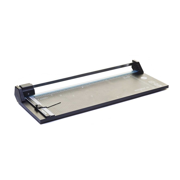
RotaTrim PT Series User manual

1
P T SERIES POWERCUTTER
PART 1
OPERATORS MANUAL
ROTATRIM LTD
8 CAXTON PARK
BEDFORD MK41 0TY
UNITED KINGDOM
Tel. 01234 224545
Fax. 01234 224550
DECEMBER 2005
Issue 5

2
CONTENTS
1. UNPACKING PAGE 3
2. INSTALLATION PAGE 3
3. HOW TO USE YOUR POWERCUTTER PAGE 4
4. FAULTFINDING PAGE 5
5. ACCESSORIES PAGE 6
6. FITTING THE EXTENDED RULE PAGE 7

3
UNPACKING
Carefully unpack the Powercutter and check for visual signs of
damage in transit.
Included with your Powercutter should be the following;
(a) One mains connecting lead
(b) One footswitch complete with plug
(c) One instruction manual.
(d) One spare cutting wheel.
(e) One extended rule.
Ensure that all the safety guards and protective covers are
securely in place.
INSTALLATION
Place the Powercutter on the bench where it is to be used (or
assemble and attach the stand - see accessories).
The Powercutter is shipped with the extended rule removed from
the baseboard.
To fit and adjust the rule, please refer to section 6 on page
7 of this manual.
Plug into the appropriate connectors the footswitch and mains
lead. The sockets are located on the left hand side face of
the Powercutter when viewed from the front.
The connectors are of different types and therefore not
accidentally interchangeable.
Connect the mains lead to the supply and switch on the
Powercutter by means of the red rocker switch located on the
right hand side of the control box.
The rocker switch will illuminate to show that the supply is
present.
Depress the footswitch and check to see that the cutting head
moves along the guide rail. The head will move alternately
from left to right and right to left each time the footswitch
is depressed.

4
If the Powercutter is switched on with the cutting head in a
midway position, depressing the footswitch will cause the head
to move to the right hand side.
If any of the above functions do not appear to work then
please ask your technician to refer to the FAULTFINDING
section of this manual.
HOW TO USE YOUR POWERCUTTER
Your Powercutter will cut paper, mountboard and card up to 4mm
thick and also some plastics and shim metals. It will also
cut framers hardboard up to 2.2mm thick.
DO NOT ATTEMPT TO CUT 3MM BUILDERS HARDBOARD.
The Powercutter is fitted with an overload protection device
which will only allow the cutting action in one direction,
i.e. from right to left.
Always position the head at the right hand side, viewed from
the front, before making a cut. The head therefore cuts
towards the rule.
To cut the material, simply place the work on the baseboard
and feed the edge to be cut under the clamping bar until it is
positioned over the base blade and then depress the footswitch
while holding the work firmly with your hands.
To cut work at right angles or with thick materials use the
rule at the side of the machine as a guide.
Depress the footswitch again to return the head to the right
hand side.
Two way cutting is possible under some circumstances. Please
contact your dealer or ROTATRIM Ltd for advice.

5
OVERLOAD
If any attempt is made to cut materials in excess of the
Powercutter's capacity, the motor will stall and the thermal
trip will disconnect the supply. If this occurs, switch off
the supply at the mains switch and remove the offending
material from the machine. After approximately two
minutes it will be possible to reset the trip by pressing the
black button located between the footswitch plug and the mains
plug on the left hand side of the Powercutter.
FAULT FINDING.
PROBLEM POSSIBLE CAUSE
1. Mains switch not illuminated Machine not plugged into
and no cut. supply or supply failure.
Supply fuse blown in plug
or on circuit board. If
fuses repeatedly blow
refer to maintenance
section.
Thermal trip needs
resetting.
2. Mains switch illuminated and Footswitch not connected
no cut. No sound from motor. or faulty. Electrical
fault in system.
Fuse blown on circuit
board.
3. Mains switch illuminated. Drive belt broken or
No cut, but motor runs. derailed. Faulty gearbox.
4. Poor cut. Edge ragged. Circular cutting wheel
blunt or contaminated
with adhesive or similar
material.

6
Cutting wheel pressure
spring broken.
Excessive wear in wheel
spindle.
Unsuitable material.
5. Circular cutting wheel rides Overload protection plate
up onto base blade and jams. broken or missing.
6. Machine cuts but does not Braking resistor open
stop abruptly at the end of circuit or relay timing
the travel. incorrect. Refer to
maintenance section.
ACCESSORIES
FLOOR STAND
A floor stand is available for your Powercutter to enable the
machine to be used in a standing position.
CATCHER
A waste catcher is available to collect offcuts created during
cutting.
This catcher is attached to the floor stand and therefore can
only be used with the stand fitted.
BASE EXTENSION
It is possible to extend the depth of the baseboard in
increments of 11 inches with a matching aluminium board.
For details of any of these accessories please contact your
dealer or ROTATRIM Ltd.
P.T. SERIES RULE
FITTING INSTRUCTIONS

7
Remove the rule from the packing tube.
Place the Powercutter on a firm surface with the cutting edge
and guide bar away from you and the motor housing on the left
hand side.
Remove the two M4 screws and nuts from the baseboard at the
left hand side of the cutting area and place the rule on top
of the baseboard such that the holes drilled in the bottom of
the rule are lined up with the screw holes in the base.
Assemble the two screws and nuts through the rule and base and
fully tighten the screw nearest the cutting blade only.
SQUARING THE RULE
Lightly tighten the other screw to hold the rule during the
squaring process.
Using a sheet of card trim all four sides using the rule,
turning the sheet in an anticlockwise direction.
Turning the card once more and aligning the card with the
cutting edge will reveal an error which is four times the
actual error. By lightly moving the rule with a mallet and
retesting, it is possible to eliminate the error completely.
Fully tighten the second screw and retest.
Small adjustments are still possible with the screws tight.
Remove the backing from the rule label and position the label
over the recess formed on the left hand side of the extrusion
such that the zero end of the scale is over the cutting edge
of the flat blade.
Press the label into position along the full length and trim
the two ends with a sharp knife.
This manual suits for next models
1
Table of contents
Other RotaTrim Cutter manuals