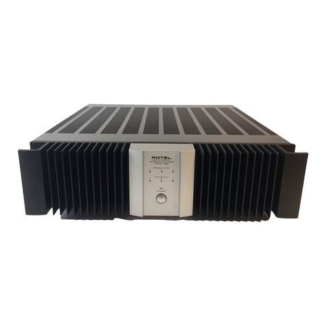
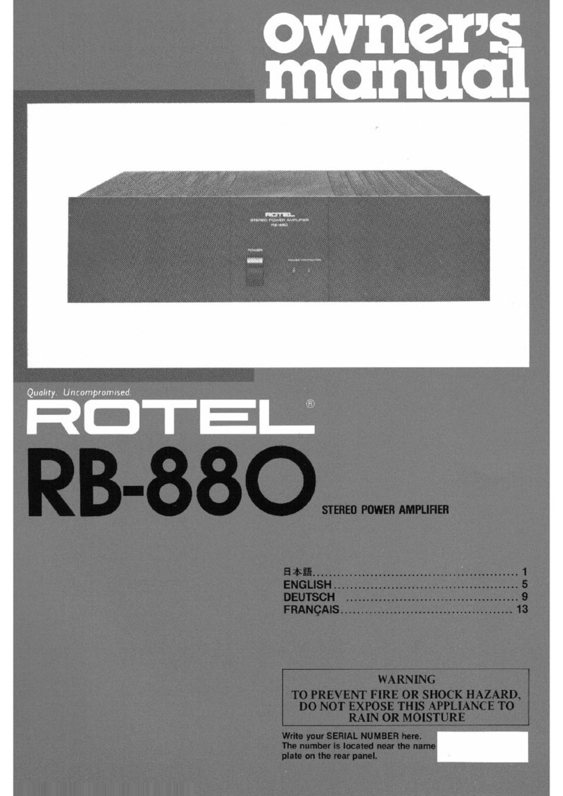
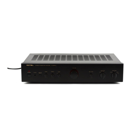
Rotel RB-890 User manual

STEREO
CONTROL
AMPLIFIER
RB-890
owners,
manual
ENGLISH....
2
DEUTSCH.
S
FRANQAIS..*..
8
...
WARNING
TO
PREVENT
FIRE
OR
SHOCK
HAZARD,
DO
NOT
EXPOSE
THIS
APPLIANCE
TO
RAIN
OR
MOISTURE
Write
your
SERIAL
NUMBER
here.
The
number
is
located
near
the
name
plate
on
the
rear
panel.
--

SAFETY
INSTRUCTIONS
CAUTION
RISK
OF
ELECTRIC
SHOCK
DO
NOT
OPEN
CAUTION:
TO
REOUCE
THE
RISK
OF
ELECTRIC
SHOCK.
DO
NOT
REMOVE
COVER
(OR
BACK).
NO
USER-SERVICEABLE
PARTS
INSIDE.
REFER
SERVICING
TO
QUALIFIED
SERVICE
PERSONNEL
•
Explanation
ot
Graphical
Symbols
/m\
The
lightning
flash
with
arrowhead
symbol,
within
an
/m
\
equilateral
triangle,
is
intended
to
alert
you
to
the
/
04
\
presence
of
uninsulated
dangerous
voltage
within
the
/
f
\
product
a
enclosure
that
may
be
of
sufficient
magnitude
/
A
\
lo
constitute
a
risk
ol
electric
shock
to
persons
/
m\
The
exclamation
poml
within
an
equilateral
triangle
is
/
I
\
intended
to
alert
you
to
ihe
presence
ot
important
/
I
\
operating
and
maintenance
(servicing)
instructions
in
the
/
I
\
literature
accompanying
the
appliance
/
*
\
EXCLUSIVE
NOTE
FOR
U.K.
If
your
unit
comes
with
a
2-core
cable
without
a
plug,
make
certain
live
and
neutral
leads
are
connected
to
the
proper
terminals.
Check
that
the
terminals
are
screwed
down
firmly
and
no
loose
strands
of
wire
are
present,
IMPORTANT
:
The
wires
in
this
mains
lead
are
coloured
in
accordance
with
the
following
code:
BLUE:
NEUTRAL
BROWN:
LIVE
As
the
colours
of
the
wires
in
the
mains
lead
of
this
ap¬
paratus
may
not
correspond
with
the
coloured
markings
identifying
the
terminals
in
your
plug
proceed
as
follows.
The
wire
which
is
coloured
BLUE
must
be
connected
to
the
terminal
which
is
marked
with
the
letter
N
or
coloured
BLUE
or
BLACK.
The
wire
which
is
coloured
BROWN
must
be
connected
to
the
terminal
which
is
marked
with
the
letter
L
or
colour
BROWN
or
RED
1,
Read
Instructions—
Ail
the
safety
and
operating
instate*
tions
should
bo
read
before
the
appliance
is
operated.
2.
Retain
Instructions
—
The
safety
and
operating
instruc¬
tions
should
be
retained
for
future
reference
3,
Head
Warnings
—
All
warnings
on
the
appliance
and
in
the
operating
instructions
should
be
adhered
to.
4.
Follow
Instructions
—
All
operating
and
other
instructions
should
be
followed
5*
Water
and
Moisture
—
The
appliance
should
noi
be
used
near
water
—
for
example,
near
a
bathtub,
washbowl,
kitchen
sink,
laundry
tub.
in
a
wet
basement,
or
near
a
swimming
pool,
etc
6.
Carts
and
Stands
—
The
appliance
should
be
used
only
with
a
carl
or
stand
that
is
recommended
by
the
manufacturer
7.
Wall
or
Ceiling
Mounting
—
The
appliance
should
be
mounted
to
a
wall
or
ceiling
only
as
recommended
by
the
manufacturer.
8.
Ventilation
—
The
appliance
should
be
situaied
so
that
its
location
or
position
does
not
interfere
with
its
proper
ventilation.
For
example,
the
appliance
should
not
be
situated
on
a
bed,
sofa,
rug.
or
similar
surface
that
may
block
the
ventilation
openings;
or
placed
in
a
built-in
in¬
stallation,
such
as
a
bookcase
or
cabinet
that
may
im¬
pede
the
flow
of
air
through
the
ventilation
openings
9.
Heat
—
The
appliance
should
be
situated
away
from
heat
sources
such
as
radiators,
stoves,
or
other
appliances
that
produce
heat
10.
Power
Sources
—
The
appliance
should
be
connected
to
a
power
supply
only
of
the
type
described
in
the
oper¬
ating
instructions
or
as
marked
on
the
appliance.
11.
Rower-Cord
Protection
—
Power-supply
cords
should
be
routed
so
that
they
are
not
likely
to
be
walked
on
or
pinched
by
items
placed
upon
or
against
them,
paying
particular
attention
to
cords
at
plugs,
convenience
recep¬
tacles,
and
the
point
where
they
exit
from
the
appliance.
12.
Cleaning
—
The
appliance
should
be
cleaned
only
as
recommended
by
the
manufacturer.
13.
Nonuse
Periods
—
The
power
cord
of
the
appliance
should
be
unplugged
from
the
outlet
when
left
unused
for
a
tong
period
of
time.
14.
Object
and
Liquid
Entry
—
Care
should
he
taken
so
that
objects
do
not
fall
into
and
liquids
not
spilled
into
the
in¬
side
of
the
appliance
15.
Damage
Requiring
Service
—
The
appliance
should
be
serviced
by
qualified
service
personnel
when:
A,
The
power-supply
cord
or
the
plug
has
been
damaged;
or
B
Objects
have
fallen,
or
liquid
has
been
spilled
into
the
appliance,
or
C.
The
appliance
has
been
exposed
to
rain;
or
D.
The
appliance
does
not
appear
to
operate
normally
or
exhibits
a
marked
change
in
performance;
or
E.
The
appliance
has
been
dropped,
or
the
cabinet
damaged,
16.
Servicing
—
The
user
should
noi
attempl
to
service
the
appliance
beyond
those
means
described
in
the
oper¬
ating
instructions
All
other
servicing
should
be
referred
to
qualified
service
personnel
17.
Grounding
or
Polarization
—
The
precautions
that
should
be
taken
so
that
the
grounding
or
polarization
means
of
an
appliance
is
not
defeated
1

ENGLISH
STEREO
POWER
AMPLIFIER
RB-890
INTRODUCTION
Weal
Rotel
want
to
thank
you
for
purchasing
our
audio
product.
Rotel
audio
products
are
designed
(o
use
the
latest
electronic
technology,
and
they
incorpo
rate
our
tong
experience
as
a
specialist
manufac¬
turer
of
audio
equipment
We
are
confident
that
you
will
find
satisfaction
in
the
high
qualily
sound
and
top
performance,
and
that
you
will
find
pleasure
m
the
functional
beauty
achieved
through
hum
an-engineering
concept.
Before
starling
operation,
please
read
this
instruction
manual
thoroughly
and
acquaint
yourself
with
(he
proper
mode
of
using
the
unit
and
all
its
connections.
We
hope
you
will
enjoy
top-notch
performance
for
many
years
to
come
BEFORE
ENJOYMENT/
POWER
SUPPLY
Follow
the
instructions
below
lor
maximum
safely:
1.
Use
a
wall
outlet
tor
power
supply
Be
sure
to
connect
the
AC
line
cord
to
a
house¬
hold
wall
outlet
Be
certain
that
the
outlet
voltage
matches
the
electrical
rating
of
the
unit,
found
on
the
rear
panel
name
plate
2*
Connecting
and
removing
AC
cord
Be
sure
to
connect
or
disconnect
the
AC
line
cord
only
after
turning
off
the
power
switch
to
prevent,
possible
shock
noise
or
damage
to
the
speakers
3.
Ventilate
the
unit
well
Never
block
any
ventilaiion
holes
at
the
top
and
bottom
of
the
unit
Be
Sure
also
to
provide
ample
ventilation
space
around
the
unit.
Poor
ventila¬
tion
may
result
in
damage
due
to
excessive
heat
4.
Do
not
open
the
cabinet
In
order
to
avoid
electric
shock
or
damage
to
the
component,
never
open
ihe
cabinet.
It
a
foreign
object
falls
inside
the
uhit
by
mistake,
turn
Ihe
power
off,
disconnect
ihe
wall
plug,
and
consult
a
qualified
electrician
or
your
dealer.
5.
Installation
Be
sure
to
place
the
unii
in
a
level
and
flat
place
where
it
is
free
from
humidity,
vibration,
high
tem¬
perature
and
not
exposed
to
direct
sunlight.
Be
careful
not
to
place
the
unit
in
a
highly
enclosed
place
such
as
near
a
wall
or
on
a
bookshelf
A
poor
ventilation
will
cause
undesirable
effects
to
the
unit.
6.
Moving
the
unit
When
transporting,
remove
the
AC
cord
from
the
wall
outlet
and
all
other
connected
cords
on
the
rear
panel
to
prevent
wire
breakage
and
short
circuits.
7.
If
the
unit
gets
wet
ft
the
unii
should
get
wet,
immediately
discon¬
nect
Ihe
AC
cord,
and
consult
your
dealer
or
a
qualified
electrician.
3,
Cleaning
and
maintenance
Do
not
use
chemicals
such
as
benzine
or
thinnerson
the
from
panel
Always
use
a
soft,
dry
cloth
to
dean
the
unit.
9.
Owner's
manual
Keep
the
owner's
manual
near
the
unit,
and
record
the
serial
number
(found
on
the
rear
panel)
on
the
cover.
EXCLUSIVE
NOTE
FOR
U.K.
If
your
unit
comes
with
a
2-core
cable
without
a
plug,
make
certain
live
and
neutral
leads
are
connected
to
the
proper
terminals
Check
that
the
terminals
are
screwed
down
firmly
and
no
loose
strands
of
wire
are
present.
IMPORTANT:
The
wires
in
this
mains
lead
are
coloured
in
accordance
with
ihe
following
code:
BLUE:
NEUTRAL
BROWN:
LIVE
As
the
colours
of
the
wires
in
the
mains
lead
of
this
apparatus
may
not
correspond
with
the
coloured
markings
identifying
the
terminals
in
your
plug
proceed
as
follows.
The
wire
which
is
coloured
BLUE
must
be
connected
to
the
terminal
which
is
marked
wilh
the
letter
N
or
coloured
BLUE
or
BLACK.
The
wire
which
is
coloured
BROWN
must
be
connected
to
the
terminal
which
Is
marked
with
the
letter
L
or
coloured
BROWN
or
RED.
CONNECTING
PREAMPLIFIER
Using
RCA
pin
cords,
connect
preamplifier
out¬
put
terminal
“L"
(left)
with
the
RB-890's
INPUT
terminal
"L",
and
the
preamplifier
output
termi¬
nal
"R"
(right)
with
the
RB-BSQ's
INPUT
terminal
'"Ft".
SPEAKERS
Use
speaker
systems
with
impedance
ratings
of
4-16
ohms,
Before
hooking
up
your
speaker
sys¬
tem,
be
sure
to
check
its
impedance,
which
should
be
indicated
either
on
the
back
of
the
speaker,
or
in
the
speaker
instruction
manual.
HOOKING
UP
SPEAKERS
Connect
the
speaker
leads
ol
the
right-hand
speaker
to
"
+
"
and
-
1
'
of
terminals
Of''
R
".
and
the
speaker
leads
of
the
left-hand
speaker
to
"
+
"
and
of
’’L"
Make
sure
each
‘
+
"
speaker
lead
is
connected
to
"
■
+-"
terminal,
and
,H
-
t
F
lead
to
the
11
*"
terminal.
Strip
1.0cm
(3/8")
of
Ihe
polyvinyl
chloride
insulation
from
the
end
of
each
speaker
lead
Twist
the
exposed
strands
tightly,
and
secure
the
end
with
a
touch
of
solder
To
conned
speaker
lead
to
the
speaker
terminal
of
the
amplifier,
rotate
the
speaker
terminal
knob
counterclockwise
to
loosen,
insert
the
stripped
end
of
the
lead,
and
firmly
tighten
the
knobonto
the
lead
2

When
using
the
unit
as
a
monaural
power
amplifier
(BTL
connection)
Conned
'
+
1
speaker
lead
to
‘
”
termi¬
nal
of
"C\
and
lead
to
+
”
termi¬
nal
of
"FT
Snip
1.0
cm
(3/6
*)
of
the
polyvinyl
chlo¬
ride
insulation
from
the
end
of
each
speak¬
er
lead.
Twist
the
exposed
strands
tightly
1
and
se¬
cure
the
end
with
a
touch
of
solder
To
connect
speaker
lead
to
the
speaker
terminal
of
the
amplifier,
rotate
the
speaker
terminal
knob
counterclockwise
to
loosen,
insert
the
stripped
end
of
the
lead,
and
firmly
tighten
the
knob
onto
the
lead
Locale
STEREO/BRIDGED
MONO
selec¬
tor
on
the
rear
panel,
and
set
it
to
BRIDGED
MONO
position.
In
this
mode,
the
INPUT
terminal
V'
(left)
of
the
RB-890
becomes
a
monaural
input
terminal.
To
this
terminal,
connect
preamplifier
output
terminal
1
V
*
(left)
or
’R"
(right),
using
a
pin
cord
The
RB-890's
INPUT
terminal
"L”
is
not
used
Caution;
In
BTL
connection,
the
potential
level
ol
the
RB-890
'BRIDGED-’
1
("
+
’’
ter
minal
of
‘
R’)
speaker
terminal
is
not
iden¬
tical
with
ground
When
using
the
unit
as
a
monaural
power
amplifier
in
that
connec¬
tion,
connect
speaker
system
to
the
speak¬
er
terminals
directly.
Do
not
attempt
to
set
a
speaker
selector
unit,
etc.,
nor
connect
speaker
leads
to
another
leads,
other
ter¬
minal
or
other
metal
part

SWITCH
AND
INDICATORS
(1)
Power
Button
Press
the
upper
part
of
this
button
to
turn
on
the
power
in
the
unit.
Press
the
lower
part
to
cut
off
the
power.
(2)
Power
Indicator
Glows
when
power
is
turned
on
with
the
power
button.
(3)
Protection
Indicator
The
indicator
normally
lights
for
several
seconds
upon
turning
on
the
power.
When
the
indicator
goes
off,
it
means
the
unit
is
in
the
normal
operating
state.
The
indicator
glows
when
abnormally
high
tem¬
perature
is
built
up
inside
the
unit.
In
such
a
case,
the
indicator
will
remain
on
until
the
temperature
inside
the
unit
drops
to
a
normal
level.
When
the
indicator
goes
offT
it
indicates
the
unit
has
returned
to
the
normal
operating
state.
OPERATION
•
Before
commencing
operation,
check
to
see
if
all
connections
are
properly
made.
•
Before
turning
on
the
power
in
the
unit,
always
be
sure
to
turn
down
the
preamplifier
volume
control
to
minimum.
1.
Turn
on
the
preamplifier.
2.
Turn
on
the
RB-890.
3.
Reproduce
a
desired
source,
and
raise
the
volume
level
on
the
preamplifier.
HUM
AND
NOISE
In
any
high
fidelity
installation,
hum
may
be
caused
by
the
interconnection
of
a
turntable,
tuner
and
amplifier,
and
speakers
as
the
result
of
wiring,
different
grounding
or
locations
of
components.
If
hum
is
experienced
with
your
unit,
disconnect
everything
but
the
speakers
from
the
unit.
Plug
in
the
turntable
and
if
hum
or
howling
appears,
move
the
turntable
away
from
the
speakers
as
much
as
possible.
Note
hum
may
also
be
induced
by
defective
cable
connections
or
by
running
the
cables
too
close
to
strong
AC
field.
When
your
unit
picks
up
noise
during
the
recep¬
tion
of
broadcasts,
causes
are
mostly
due
to
ex¬
ternal
objects
such
as
fluorescent
lamps
and
house
appliances
using
motor
or
thermostat,
or
others
that
may
induce
the
noise.
Either
relocating
the
unit
away
from
the
noise
sources
or
using
an
improved
outdoor
antenna
may
readily
solve
the
problem.
In
the
event
you
cannot
find
the
cause,
consult
your
dealer
or
a
qualified
electrician.
PROTECTION
CIRCUIT
The
RB-890
incorporates
thermal
protector
to
prevent
accident
or
damage.
If
for
some
reason
the
protection
circuit
is
activated,
there
will
be
a
sudden
cut-off
of
sound
from
the
speakers,
and
the
protection
indicator
will
light
up.
If
no
sound
is
produced,
the
reason
may
be
due
to
the
functioning
of
the
protection
circuit.
First,
turn
off
the
power
and
disconnect
the
plug
from
the
electrical
outlet.
Then
locate
and
remedy
the
cause
of
the
trouble.
When
the
thermal
protec¬
tor
is
activated,
the
unit
will
start
functioning
au¬
tomatically
after
the
temperature
is
lowered
again.
If
the
protection
circuit
is
activated
again
despite
taking
the
above
action,
cut
off
the
power
sup¬
ply
from
your
entire
audio
system
and
consult
your
dealer
or
a
qualified
electrician.
Note:
The
protection
circuit
will
normally
oper¬
ate
to
prevent
a
popping
noise
from
being
gener¬
ated
upon
turning
on
the
power.
No
sound
is
produced
for
several
seconds
after
turn-on
VOLTAGE
SELECTION
Not
available
for
U.K.,
Canada
and
Scandinavia
The
unit
is
a
variable
voltage
equipment
that
can
run
on
120V,
220V
or
240V
power
supply.
Your
unit
should
already
be
preset
at
the
proper
voltage
for
use
in
your
area.
However,
if
you
move
to
an
area
where
the
power
supply
voltage
is
different,
consult
your
dealer.
SPECIFICATIONS
Continuous
Power
Output
160
watts*
per
channel,
min.
RMS
both
channels
driven
into
8
ohms
from
20
to
20,000
Hz
with
no
more
than
0.03%
total
harmonic
distortion.
Rated
power
output
(BTL
connection)....
360Watts(mono)
min.RMS
driven
into
8
ohms
from
20
to
20,000
Hz
with
no
more
than
0.03%
total
harmonic
distortion
DIN
Power
Output
280
watts
per
channel
(1
kHz,
4
ohms,
1%
THD)
Total
Harmonic
Distortion
No
more
than
0.03%
(continuous
rated
(20
to
20,000
Hz)
power
output)
No
more
than
0.03%
(continuous
1/2
rated
power
output)
No
more
than
0.03%
(1
watt
per
channel
power
output,
8
ohms)
Intermodulation
Distortion.No
more
than
0.03%
(continuous
rated
(60
Hz
:
7
kHz
=
4:1)
power
output)
No
more
than
0.03%
(continuous
1/2
rated
power
output)
No
more
than
0.03%
(1
watt
per
channel
power
output,
8
ohms)
Output:
Speaker
4-16
ohms
Damping
Factor
380
(20
to
20.000
Hz,
8
ohms)
Input
Sensitivity/Impedance.1.0V/22
kohms
Frequency
Response
.15
to
130,000
Hz,
+
0
dB,
-1.0
dB
Signal-to-Noise
Ratio
(IHF,
A
network).120
dB
Power
Requirement.120V/60
Hz,
220V/50
Hz,
240V/50
Hz,
or
120,
220,
240V/50-60
Hz
(depending
on
destinations)
Power
Consumption
800
watts
Dimensions
(overall)
430
(W)
x
109
(H)
x
349
(D)
mm
16-15/16"
x
4-11/16"
x
16-15/16"
Weight
(net)
.13.0
kg/28.7
lbs.
•
Specifications
and
design
subject
to
possible
modification
without
notice.
•
*
Measured
pursuant
to
the
Federal
Trade
Commission’s
Trade
Regulation
Rule
on
Power
Claims
for
Amplifiers
(applicable
to
the
U
S
A
only).
4
Table of contents
Other Rotel Amplifier manuals

Rotel
Rotel RB-1090-3 User manual

Rotel
Rotel RMB-1585MKII User manual

Rotel
Rotel RB-1010 User manual

Rotel
Rotel RHB-05 User manual

Rotel
Rotel RB-951 mkII User manual

Rotel
Rotel RA-985BX User manual
Rotel
Rotel RA-1210 User manual

Rotel
Rotel RC-1550 User manual

Rotel
Rotel RA-1210 User manual

Rotel
Rotel RMB-100 User manual
Popular Amplifier manuals by other brands

Sonodyne
Sonodyne DE 4348 owner's manual

Choice Select
Choice Select CHO4020 user guide

Williams Sound
Williams Sound pocketalker 2.0 user manual

Clarion
Clarion XC6210 Owner's manual & installation manual

Roksan Audio
Roksan Audio Platinum STI308 user manual

Key Digital
Key Digital Xplosion Series KD-CDA12P Specification sheet