Rotonivo RN 4000 Series Owner's manual

1
2
3
4
5
6
7
8
9
10
11
12
Rotonivo®
RN 4000 gi010106 1
Level limit switch
Series RN 4000
Technical information / Instruction manual
page G
Page
Introduction G2
-----------------------------------------------------------------------------------------------------
Mode of operation G2
-----------------------------------------------------------------------------------------------------
Approvals G2
-----------------------------------------------------------------------------------------------------
Technical data G3
-----------------------------------------------------------------------------------------------------
Electrical connection G4
-----------------------------------------------------------------------------------------------------
Safety items G5
-----------------------------------------------------------------------------------------------------
Mounting G5
-----------------------------------------------------------------------------------------------------
Remarks for use in Hazardous Locations G7
Subject to technical change and price change. We assume no liability for typing errors.
All dimensions in mm (inches). Different variations to those specified are possible.
Please contact our technical consultants.
All units of this information are CE - certified.
Table of contents

Rotonivo®
1
2
3
4
5
6
7
8
9
10
11
12
RN 4000
gi010106
2
1
2
Level limit switch
Series RN 4000
Technical information / Instruction manual
page G
Introduction
• TheROTONIVORN4000isacosteffectiveelectromechanical
level-limit-switch and is used for level monitoring of bulk
goods. It is used wherever
- dustlike
- powdery
- granulated
- granular
media are handled.
Mainly it is used in easy applications with little mechanical loads
• Designedlikeamodularsystem,ROTONIVOlevellimit
switches are used as
- Full detectors
- Demand detectors
- Empty detectors
in
- Silos - Bunkers
- Hoppers - Weigher containers
- Storage containers - Discharge pipes
- Small containers
• ROTONIVORN4000levellimitswitchesare
- compact - simple
- robust - reliable
- maintenance-free - insensitive to
environmental influences
• ROTONIVOlevellimitswitcheshaveprovedthemselvesin
different industries such as:
- Chemical industry - Food processing industry
- Wood industry - Mechanical industry
- Building industry - Plastics industry
Mode of operation
A low revolution synchronized gear motor drives a rotating measuring
vane,whichisforexamplemountedinacontainer
(picture 1).
Assoonasthemateriallevel,whichistobemonitored,reachesthe
measuringvane,thevaneishinderedinitsrotation.Themotoris
freely suspended within the housing. The caused reaction torque is
used to operate a micro switch giving a suitable electrical signal and
to stop the motor (picture 2).
Whenthevanebecomesfreeagainduetothedropinmateriallevel,
aspringdrawsthemotorbackintooperatingposition,themicro
switch returns to its initial position and the motor is switched on. The
electrical output signal is then switched over (picture 1).
Approvals
FortheROTONIVOtypeRN4001approvalsforHazardousLocations
category 1/3 D (zone 20/22) according directive 94/9/EG are
available.
CE EMC EN 61326/A1
Gen. purpose EN 61010-1
Introduction / Mode of operation
Microswitch
motor
Switching
part
Microswitch
output signal

1
2
3
4
5
6
7
8
9
10
11
12
Rotonivo®
RN 4000 gi010106 3
Level limit switch
Series RN 4000
Technical information / Instruction manual
page G
Technical data
Dimensions Electrical data
For detailed dimensions of the types RN 4001 see pricelist. Supply voltage:
Installed load:
Connection terminal:
Screwed cable gland:
Signal output:
Connection diagram:
Protection class:
Operating conditions
Container over-pressure:
Power density:
Feature of bulk material:
Maintenance:
Temperature inside
container:
Ambient temperature
of the housing:
220..230V50-60Hz
(changeableto110..120V)
110..120V50-60Hz
(changeableto230..240V)
48V50-60Hz(changeableto24V)
24V50-60Hz(changeableto48V)
24VDC
all voltages + 10% / -15%
Multivoltage
230V50Hz/115V50-60Hz/24VDC
all voltages ± 15%
3VA(3W)
1xmax.1,5mm2
1xM20x1,5(option2xM20x1.5)
floating microswitch
ACmax.250V,2A,500VA(cosj= 1)
DCmax.300V,2A,60W
insideofcover,datasheet
I
-0.5bar ... +0.8bar
version with approval ATEX 1/3 D
(zone 20/21): see page G7
min. 100g/l
dustlike,powdery,granulated,granular
not required
-20°C upto +80°C
-20°C upto +60°C
Mechanical data
Housing: die-casted housing plastic PA6 with
fibreglass; RAL 5012 blue
Enclosure: IP 66 to EN 60529
Process connection: thread according to selection;
flanges on request
Material process connection: plasticPA6withberglas,black;
version with approval ATEX 1/3 D
(zone 20/22): aluminium
Material vane shaft: stainless steel (1.4305/303)
Material measuring vane: stainless steel (1.4301/304) or
plasticPP,black
Tolerance length „L“: ± 10mm (pendulum shaft or rope
extension)
Bearing: slidebearing,high-grade
Sealing: radial rotary shaft sealing DIN 3760
material : NBR (Acrylnitril-Butadien-
rubber)
Friction clutch: protection of the gear against impacts
of the measuring vane
Pickup delay: approx.1,3sec
Sensitivity: adjustable via the restoring force of
the spring or geometry of measuring
vane
Speed of measuring vane: 1 1/min
Max.surfacetemperatureforuseinHazardousLocations(ATEX):
see page G7

Rotonivo®
1
2
3
4
5
6
7
8
9
10
11
12
RN 4000
gi010106
4
7 6 5 1 1 2 PE
L N PE
L+ L- PE
L N
7 6 5
Signal
1 1 2 PE
L+ L- PE
L N
1 1 2 PE
7 6 5 7 6 5
7 6 5
Level limit switch
Series RN 4000
Technical information / Instruction manual
page G
Externalequipotential
bonding terminal
For ATEX 1/3 D
zone 20/22):
Connect with equipotential
bonding of the plant.
Switching logic
DC design
Multivoltage
AC design
Supply-voltage-
selector
Viewofprinted
circuit board
Set the supply-
voltage-selector
to the desired
voltage
Version
multivoltage
green
red
VersionAC/DC
ACmax.250V,2A500VA(cosj = 1)
DCmax.300V,2A60W
Terminals1xmax.1.5mm2
Protection against static charching:
The PE terminal of the unit must be grounded to
avoid static charging of the unit.
This is particularly important for applications
with pneumatic conveying.

1
2
3
4
5
6
7
8
9
10
11
12
Rotonivo®
RN 4000 gi010106 5
Level limit switch
Series RN 4000
Technical information / Instruction manual
page G
•
•
•
•
•
•
Installation,maintenanceandcommissioningmustbecarriedout
by qualified technical personnel.
For devices to use in Hazardous Locations ATEX1/3 D (zone
20/22) the requirements of the EN 50281-1-2 (e. g. regarding dust
deposits and temperatures) must be observed.
Switch off the supply voltage before opening the housing.
Dangerous voltage!
Operateonlywithclosedlidofthehousing.
Useafuseforthesupplyvoltage(max.4A).
A voltage disconnecting switch must be provided near the switch.
A RCCB protection switch is necessary.
•
•
•
•
•
•
Compare the mains voltage applied with the specifications given on
the label before switching the device on.
Forterminalconnectionofthedevice,thelocalregulationsorVDE
0100 (regulations of German electrotechnical engineers) must be
observed.
Inthecaseofincorrecthandlingorhandlingmalpractice,theelectric
safety of the device cannot be guaranteed.
For devices to use in Hazardous Locations ATEX 1/3D (zone 20/22)
the respectively valid installation regulations must be observed.
Isolatingsignaloutput-mainsvoltage:3kV~
Provide protection for relay contacts to protect the device against
spikes,ifinductiveloadsareconnected.
Safety items
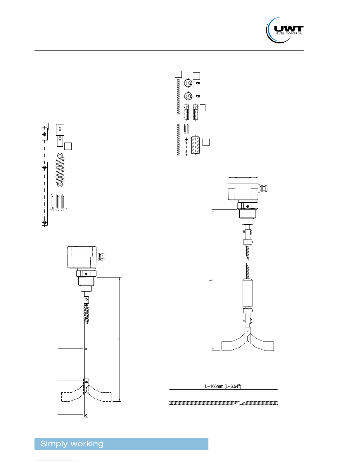
The unit must be mounted with the thread or the flange on the container.
Mounting may be vertical, oblique or horizontal. For the individual
mountingoftheseveralROTONIVO-modelsseepricelist.
The electrical connections are made in accordance with the connection
diagram.Makesure,thatthecableinthescrewedcableglandisseated
tightly without fail. For models according to ATEX 1/3D a pull relief must
be provided for the connection cables.
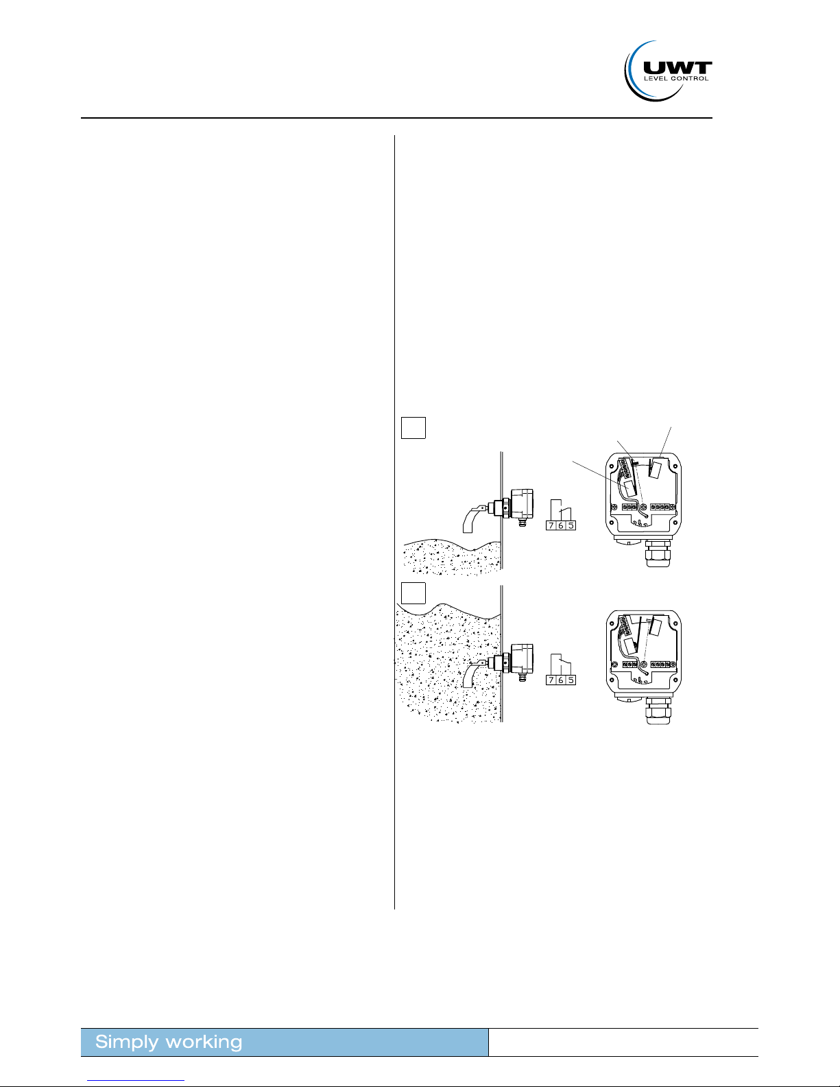
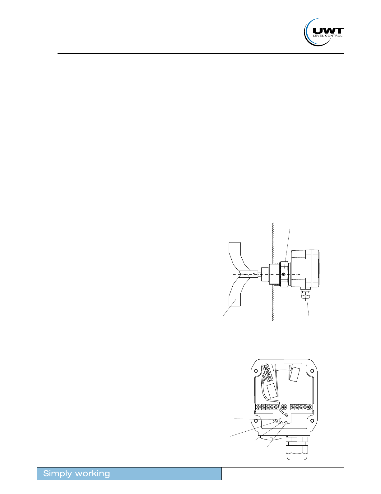
Aftermounting,turnthehousingintherightdirection.Thescrewedcable
glandmustshowdownwards(seedrawingrighthand).Thismakessure,
thattheunitworksneandprotects,thatwaterentersintothehousing
through the screwed cable gland.
When the unit is used outside, we recommend to use the weather-
protection-cover. It protects the unit against moisture, heat, cold and
prevents the formation of condensation water in the interior of the
housing.
Adjusting the unit onsite is not required.
Mounting
The spring is adjustable in 3 positions. It should be changed only if
necessary.
„Fine“: for light material;
„Medium“: suitable for nearly every material;
„Coarse“: for very sticky material;
Factory setting is „medium“.
The spring can be changed via small pliers.
Adjustment of the spring
Cut one side of the
universal vane:
- in case of empty or demand
detector at any rate;
- to feed the vane through
the mounting hole;
Correct mounting:
Screwed cable gland
points down
Fixthescrewafter
turning the housing in
the right direction
spring
fine
medium
coarse

Rotonivo®
1
2
3
4
5
6
7
8
9
10
11
12
RN 4000
gi010106
6
1
2
13
2
4
Level limit switch
Series RN 4000
Technical information / Instruction manual
page G
Shaft extensions
Therearetwodifferentshaftextensionsavailable:
Either upto 1m with the kit „Pendulum shaft“ or more robust upto 2m
withthekit„Ropeextension“.Theropecanbecuttothedesiredlength.
Kit „Rope extension“
Withthekit„Ropeextension“theshaftofthe
RN4001isextendedbya8mmstainlesssteel
rope (1). The rope is mounted with the shaft and
the measuring vane by each a bush (2) and a
clamp ring (3). The rope weight (4) is put over
the rope to tight it.
ThekitisavailableforL=2m.Otherextension
lengths are possible byy cutting the rop to the
required length.
Kit „Pendulum shaft“
Thekit„Pendulumshaft“consistsofanextension
shaft (1) to be mounted with a spring (2) on
the shaft of the RN 4001. Each 100mm there
are drilled holes in the shaft for mounting the
measuring vane. This enables to mount the vane
atdifferentextensionlength"L".Incaseofhigh
material density it is recommended to cut the
shaft below the vane.
Thekit„Pendulumshaft“isavailableformax.
L=0.5mormax.L=1.0m.
Mounting
RN 4001 with
rope extension
Example:
RN 4001 with
pendulum shaft
L = 0.5m;
measuring vane
mounted at
L = 0.4m
Length of rope:
L = 0.3m
L = 0.5m
L = 0.4m

1
2
3
4
5
6
7
8
9
10
11
12
Rotonivo®
RN 4000 gi010106 7
Level limit switch
Series RN 4000
Technical information / Instruction manual
page G
Remarks: ATEX
Remarks for use in Hazardous Locations according to ATEX
Zone classification
The approval according to ATEX (directive 94/9/EC) for Hazardous Areas
category 1/3 D (zone 20/22) determines the following classification:
Device category to 94/9/EG usable in zone
1 D 20,21,22
3 D*) 22
*)incaseofconductivedust,additionalrequirementsforthe
installation are necessary.
General Notes
Marking Devices with EX approval are marked on the name plate.
Process pressure
for ATEX
The device construction allows process over-pressure upto 0.8 bars (11.6psi) (see name plate).
These pressures are allowed for test purposes. The definition of the ATEX is only valid for a container
overpressure between -0.2..+0.1 bar (-2.9..+1.45psi).
For higher or lower pressures the approval is not valid.
Process and ambient
temperature
The permitted temperature ranges are marked on the name plate.
Maximumoperatingtemperature
Thefollowinginformationshowsthemaximumsurfacetemperatureatthewarmestpartoftheunitwhichcanoccurin
failure case (according to ATEX definition).
maximum
Surface
temperature
in °C
Ambient
temperature in
zone 22 in °C
Medium
temperature in
zone 20 in °C
95 60 80
85 50 70
75 40 60
Zone 20
(category 1)
Zone 22
(category 3)
Container wall
outside
container
inside
container

This manual suits for next models
1
Table of contents