RotorWay Exec 162 Instructions for use

RotorWay International
Exec 162F Construction Manual
Section 1
Standard Construction
Procedures
Section 1
Page A
Procedures covered in this section:
Proper use of tools; general fitting and alignment procedures; aircraft (AN) hardware; working with 4130 steel; working
with aluminum; working with plexiglass; working with fiberglass; working with plastic filler (Bondo); painting and finishing;
plating and anodizing; Dzus fasteners and nut plates.
Cards used in this section:
None
Prints used in this section:
None
Templates used in this section:
None
Tools required for this section:
None

RotorWay International
Exec 162F Construction Manual
Section 1
Page B

RotorWay International
Exec 162F Construction Manual
Section 1
Page 1
Rev. 1 3/99
1. PROPER USE OF TOOLS
A. Drills and Reamers
1. When a very close tolerance fit is required, use a “D” drill (.246") for drilling 1/4" AN bolt holes. 1/4" AN bolts are
normally .003" undersize. The bolts will fit very snug and will have to be lightly hammered in place with a plastic
mallet. This method should be used only for 1/4" bolts that hold a pulley on a shaft, the bolts that hold the main
sprocket to the hub, and in similar applications.When the fit is less critical, a standard 1/4" drill bit should be used.
2. In order to drill a hole closer to the exact size, always start with a slightly smaller drill, then finish the hole with a
sharp drill of the exact size.
3. When attempting to drill 4130 steel, always use a slow drill speed and apply pressure. Drills must be sharp; a dull
drill will become hot and harden the material. Once the metal hardens it will be almost impossible to make the drill
cut through. In such a case, it will be necessary to heat the material with a torch until it is cherry red. Allow the
material to air cool completely before attempting to re-drill, this time with a sharp drill. (Do not quench.)
4. A reamer may be used for final sizing a precision hole to within ± .001". A good rule of thumb is to use half the
speed for reaming that you do for drilling. Use plenty of oil.
5. To drill out a rivet, use a drill the size of the rivet. Start drilling in the center of the rivet head and rotate the drill in
a circle until the head of the rivet comes off. Stop drilling and use a punch to remove the shank.
B. Torque Wrench
A Torque wrench is a must for precision assembly. If you do not already have one, purchase a 3/8" drive micrometer
type and make sure that it has a scale on it marked in ft.lbs. The main blade retention bolts have the highest torque
of any bolt on the ship and are torqued to 70 ft.lbs. Therefore, it is not necessary to have a torque wrench that reads
over 100 ft.lbs. A heavier torque wrench will not give as accurate a reading at the low end of the scale (6 - 10 ft.lbs).
C. Dial Indicator
A dial indicator is an absolute must for main rotor blade rigging procedures. The indicator must have a dial that reads
in .001" increments, along with a magnetic base and gooseneck to hold it.
A dial indicator can be used for checking the straightness of a shaft as follows: support both ends of the shaft in “V”
blocks. Place the point of the dial indicator on top of the shaft in the center.The total indicated reading (TIR) for a 360
degree rotation can be noted.
A dial indicator is also useful for checking relative height settings. Its main use on the EXEC 162F will be setting lead/
lag adjustments on the main rotor system.
D. Dial Caliper
A 6" dial caliper with a needle travel of .100" per revolution is a very useful tool for checking precise lengths and
thicknesses.
E. Protractor Level
A protractor level is used throughout the construction, and also for rigging procedures and rotor system adjustments.
A quality protractor level will read in increments of 1/2° or less. An electronic protractor is a good option. In order to
check the quality of the level you are purchasing, zero the bubble and place it on a level surface. Rotate the level 180°
to the surface and see if the bubble maintains its centered relationship. Also, the lines on each side of the bubble
should be as close as possible to the end of the bubble.
2. GENERAL FITTING AND ALIGNMENT PROCEDURES
A. Do not force bolts into holes that are undersized. Pass a sharp drill of the appropriate size through the hole first. Do not
use excess force to drive a bolt in place with a hammer. Whatever you put together will at some time have to be taken
apart. Bear this in mind as you complete the construction.
B. Fit shafts and mating parts carefully. If a bearing does not slide onto the appropriate shaft, do not hammer it in place
(it’s OK to tap lightly). Use 400 to 600 grit sandpaper to sand the shaft down slightly until the bearing fits. In most
cases, there will only be small burrs which need to be removed.

RotorWay International
Exec 162F Construction Manual
Section 1
Page 2
Rev. 3 10/01
C. There are three types of fits normally used in assembling shafts and bearings:
1. The press fit. A press fit is one which requires a press to install the bearing. It may take anywhere from one
hundred to several hundred pounds of pressure to press the bearing on the shaft. RotorWay does not expect the
builder to work with this type of fit because it will make assembly impossible for a builder in the field.
2. The slip fit. A slip fit is one in which the bearing may be rotated onto the shaft by hand. The inner race should be
rotated as the bearing is slid on the shaft. It will take a little hand pressure to force on a slip fit; however, no other
means but hands will need to be used.There are several slip fits used on the EXEC 162F helicopter. In each case,
on final assembly, you will clean the surfaces and coat them with Loctite prior to installing the bearings. A slip fit
plus Loctite results in a fit almost as permanent as a press fit.
3. The loose fit. A loose fit is one in which the bearing may be dropped onto the shaft and will slide in place. If this
fit results in over .001" in airspace around the shaft circumference, it is too loose for a highly loaded operation,
even with the use of Loctite.
D. How to Remove Loctited Bearings:
Removing a bearing which has been Loctited in place will require heating the inner race of the bearing. A bearing
puller should be installed on the bearing and a slight pressure applied to it. As the inner race is heated, the bearing will
pop loose. Obviously, the bearing must be replaced on reassembly, as the seals will have been damaged during the
heating process. Do not place heat directly on the shaft, only on the inner race of the bearing.
3. AIRCRAFT (AN) HARDWARE
A. Several types of hardware are used on RotorWay helicopters including standard AN hardware and various military
specifications (MS). Do not substitute the original hardware with bolts made from a lesser strength material. Hardware
store variety nuts and bolts are normally mild steel and are not heat treated. AN hardware is twice as strong as most
mild steel bolts of the same size.
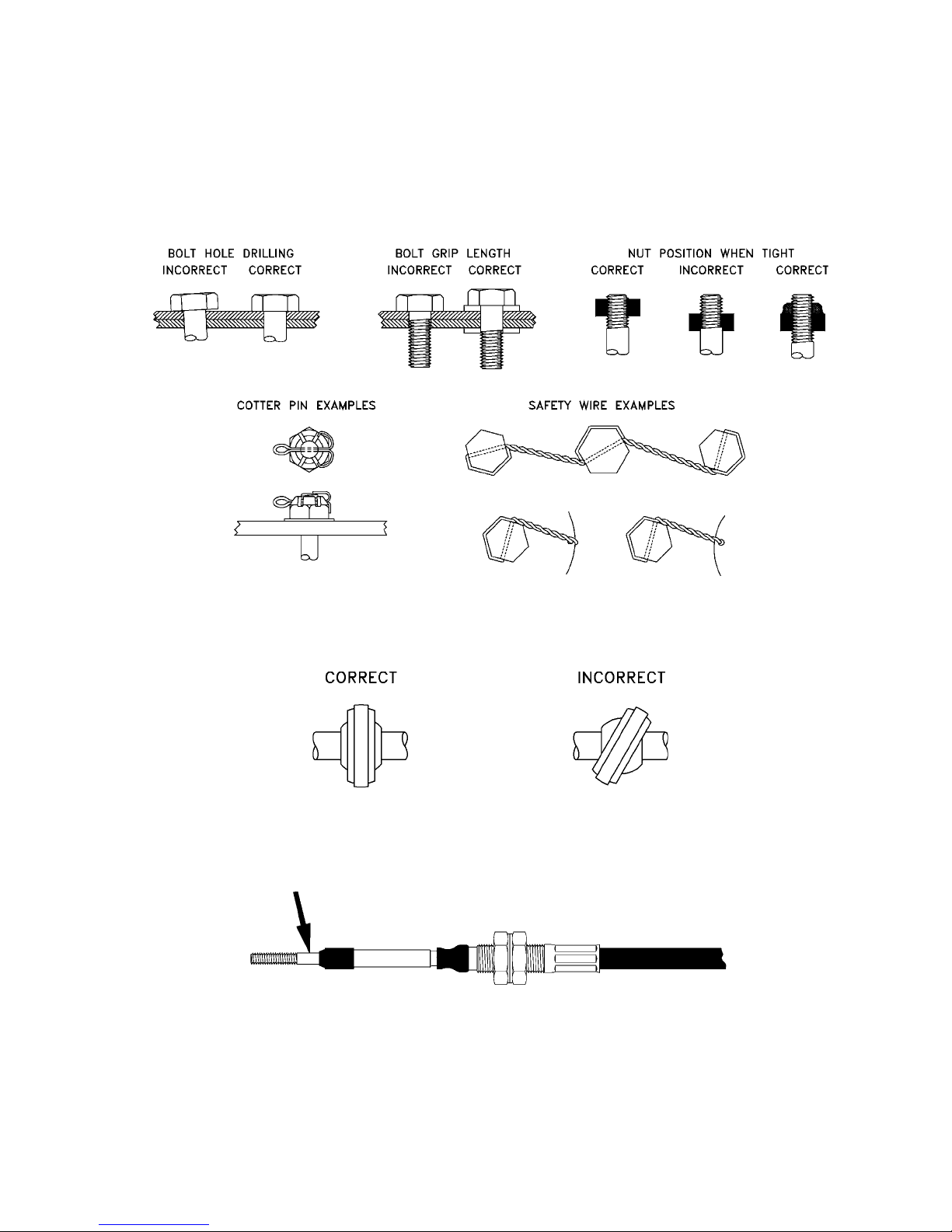
B. Elastic lock nuts (also called fiberlock nuts) are used in many places on the helicopter. These nuts are made with a
fiberous collar in one end to keep them from vibrating off. After tightening, a minimum of 1 and a maximum of 3
threads should extend past the end of the nut. Nuts must not bottom out on the threads. Do not attempt to tap threads
further on an AN bolt. It is acceptable to use up to 2 washers underneath the head of the bolt and/or the nut prior to
going to the next shorter length of bolt. Every length of every size of AN hardware is very difficult to find, therefore the
use of extra washers is occasionally necessary.
C. Unless otherwise noted, all bolts used as pivots or hinges in operation must use castellated nuts and cotter pins.
(Examples: swash plate scissor and tail rotor actuator arm). In these applications, the nut must not be tightened to a
point where the bolt is not free to rotate. The cotter pin should fit snug in the hole.
D. Do not use elastic lock nuts on bolts which have cotter pin holes in the threaded end, as the sharp edge of the hole will
cut the locking device rendering it ineffective.
E. All bolts without elastic lock nuts or other locking devices must be safety wired to prevent them from vibrating loose
during flight.
F. Use the following torque specifications on 3/16" through 3/8" bolts, nuts and set screws unless otherwise noted in the
construction drawings or photo sequence:
BOLT SIZE TORQUE
3/16" .................... 4 ft. lbs.
1/4" ...................... 7 ft. lbs.
5/16" .................. 12 ft. lbs.
3/8" .................... 16 ft. lbs.
A bolt and nut installed through thin walled material (or tubing without a bushing) should be tightened until snug and
secure, without causing the material to distort. For example, the bolts which attach the vertical trim fin to the bracket
should not be tightened to the specified torque value if it would crush or distort the airfoil.
G. Make sure bolt holes are perpendicular (90 degrees) to the surface involved and are not oversized. A bolt in an
incorrectly drilled hole will not carry its shear load until the surface that is in contact with the bolt has deformed.
Contact Rotorway before drilling oversized or elongated holes in critical components, as there are many factors to be
considered.

RotorWay International
Exec 162F Construction Manual
Section 1
Page 3
H. The bolt “grip length” is the unthreaded portion of the bolt shank and should always be correct. Normally the grip
length is equal the thickness of the objects being bolted together, though bolts of slightly longer length can be used
with washers.
I. Washers should be used under bolt heads and nuts unless otherwise specified. A washer guards against mechanical
damage to the material and can also help prevent corrosion.
J. When installing a rod end, hold it so that it does not rotate when the jam nut is being tightened.The rod end should be
able to pivot an equal distance in both directions, instead of being cocked to one side, with the nut tight.
K. When tightening the nuts on the ends of control cables, the threaded rod (arrow) must be held to prevent the inner
cable from twisting inside the housing. Twisting may damage the cable and cause it to break.
L. Always use steel rivets (instead of aluminum) in areas where strength is critical, such as tail boom and tail rotor
components. Aluminum pop rivets are not structural and should only be used in low-stress areas, for example holding
nut plates. Correct grip length of the rivets is determined by the thickness of the materials being fastened.

RotorWay International
Exec 162F Construction Manual
Section 1
Page 4
Rev. 1 8/00
4. WORKING WITH 4130 STEEL
A. Bracketry
1. Cut brackets to size using the templates supplied. If there is a grain direction specified on the template, paste the
label on the material in that orientation.
2. Use a 24 teeth per inch hack saw blade or a low speed band saw to cut out bracketry. Radius all internal corners
smoothly with a rat-tail file.This will help prevent cracking during the bending operation.
3. If a bracket is to be bent, hold it in a vise with aluminum jaws; or bend a piece of scrap, then bend the bracket over
the scrap material. As you hammer the bracket around the scrap, it will follow the radius of the scrap piece. Check
for cracking after you have formed the bend. Heat may be applied during the process for brackets over 1/16"
(.062") in thickness.
4. It is good practice to remove all sharp edges when working with sheetmetal. Various types of deburring tools are
available, or use a file or sandpaper.
5. WORKING WITH ALUMINUM
A. .025" aluminum may be cut with left and right hand metal cutting shears. .050" may be cut with a band saw or hack
saw. Remove all sharp edges after cutting.
B. The same rules apply for bending aluminum as for 4130 steel. If the radius is too sharp, the material may crack. .025"
aluminum may be clamped in a vise against a board and bent around the end of the board. Sufficient sheet metal has
been supplied in the kit; take care to position the templates in such a manner that you use up the material effectively.
6. WORKING WITH PLEXIGLASS
A. Use caution when handling the plexiglass windscreen. The edges of the windscreen should be immediately sanded
smooth to prevent possible cracking during the handling process. A file or air sander may be used for rough grinding,
then finish by hand using 80 to 100 grit wet/dry sandpaper. During any sanding process, be careful to support the
material adequately in the area in which it is being worked. Be especially careful if you are using an air sander (2" to
3" diameter recommended).
B. Do not remove the protective film coating from the windscreen, doors and other plexiglass components until all work
on them has been completed.
C. When drilling cleco holes in plexiglass, try using a Uni-Bit or step drill. This type of drill is less likely to cause the
material to crack.
D. Before the windscreen is final installed, the screw holes must be drilled oversize (using a 5/32" drill) so that the
windscreen is able to move slightly. There should not be any stress on the windscreen. The fasteners that hold the
windscreen should be snug, not over tightened. They should be secure and just able to be turned with a screwdriver.
E. Clarity may be maintained in the windscreen by frequent polishing with mirror glaze.
F. If a crack begins to form in plexiglass, immediately drill the end of the crack with a small drill (about 1/16" diameter) or
the crack will propagate like a zipper.
7. WORKING WITH FIBERGLASS
WARNING: WHEN WORKING WITH FIBERGLASS, MAKE SURE THE AREA HAS ADEQUATE VENTILATION.
A. Locate additional supplies, including: acetone, rubber squeegee, 1" to 2" wide brushes, and plenty of rags. Rubber
gloves and eye protection should also be used.
B. Prior to fiberglass application, prepare all surfaces by sanding and cleaning with acetone.
C. MIX 20 drops of catalyst with 4 oz. of resin.The hotter the outside temperature, the less catalyst is used.The resin should
not take more than 35 minutes to “kick”.Test a small sample to get a feel for what works best (20 drops = 1/2cc).
D. All components which are fiberglassed to one another will use a layer of mat or cloth to bond the two surfaces
together. Materials provided include 2 oz. mat and cloth.These may be used in two or four ply thickness as appropriate
(one mat or one cloth equals one ply). Do not start any fiberglass process unless you have some acetone and rags on
hand for clean up.

RotorWay International
Exec 162F Construction Manual
Section 1
Page 5
Rev. 1 1/01
8. WORKINGWITH PLASTIC FILLER (Bondo)
Before plastic body filler is applied to any surface, the surface must be sanded lightly and cleaned with acetone. Cream
hardener is added to activate the filler. Mix only a small amount that can be used within 3-4 minutes. Knead the tube of
cream hardener thoroughly before using. Dispense the desired amount of filler on a clean flat non-porous surface such as
metal or plastic. Use 1/4 teaspoon hardener to 4 tablespoons (2-1/2 oz.) filler or 2-1/2 grams hardener for 100 grams filler.
Mix with firm pressure using a back and forth wiping motion. Mix with a plastic spreader or putty knife to a uniform color at
room temperature. Apply thin to the surface, avoid using too much at a time. It is easy to mix another batch and apply more
material but the sanding process is time consuming. The surface should be dry and tack-free within 20-25 minutes. The
fastest method of finishing is to cut the Bondo off with a “cheese grater” file as soon as it becomes firm. Finish to final
configuration by hand sanding.
9. PAINTING AND FINISHING
We recommend that you talk to a local aircraft painter or paint supplier to find out what preparation and materials give best
results in your climate. For instance, in some areas near the ocean, zinc chromate primer is required to protect the
aluminum from salt air. If you do not have much experience spraying paint, you may prefer to have a paint shop do the
work for you. Our general recommendations are as follows:
Body, tail boom and main rotor blades: primer as required, 2 part Polyurethane paint.
Airframe and landing gear: sandblast with fine grit sand, 2 part epoxy paint.
10. PLATING AND ANODIZING
Contact RotorWay for recommendation of items that you want to plate or anodize. For example, a high stress item cannot
be plated. Have the plating done ONLY by a company qualified to plate aircraft parts.
11. DZUS FASTENERS AND NUT PLATES
Dzus fasteners, commonly called “Dzus buttons”, are
composed of a stud, grommet and spring. The studs and
springs are made of steel, cadmium plated to prevent
corrosion.The grommet is made from aluminum alloy and
holds the stud in place on the panel. The Dzus fastener
locks with only 1/4 turn clockwise, and unlocks
counterclockwise.

RotorWay International
Exec 162F Construction Manual
Section 1
Page 6
DZUS BUTTONS
Photo #1
Use a hand drill to open the 1/8" hole to 5/16" for
the Dzus button.
Photo #2
Make a drill template from a strip of flat metal, 1-3/4"
wide and about 6" long. Drill a 5/16" hole, centered
widthwise, close to one end. Install a Dzus button in
the hole and place the spring on the back of the
strip, parallel to the end. Use the spring to locate
and drill two holes for the 1/8" pop rivets. Remove
the Dzus button and spring, and install a rod in the
5/16" hole. (Use a short 5/16" bolt with the thread
sawed off if you do not have anything else.)
Photo #3
Use the drill template to drill the 1/8" pop rivet holes.

RotorWay International
Exec 162F Construction Manual
Section 1
Page 7
Photo #4
Use a large drill bit to countersink the 1/8" pop rivet
holes.
Photo #5
Use a hand drill and a 3/8" bit to open the Dzus
button hole. Then install the spring wire with pop
rivets.
Photo #6
Use a hand drill and a 3/8" bit to open the hole for
the grommet. Install the grommet with the large
end on the same side that the head of the button
will be on. Place it on a hard surface with the
pointed end of the tool toward the grommet.
Hammer to expand the small end.

RotorWay International
Exec 162F Construction Manual
Section 1
Page 8
Photo #7
Install the Dzus button.
Photo #9
Remove the tool and check for even compression
of the grommet.
Photo #8
Place the head of the Dzus button on a hard
surface, and place the open end of the tool over
the shank of the Dzus button. Hit the pointed end
of the tool to lock the Dzus button to the grommet.

RotorWay International
Exec 162F Construction Manual
Section 1
Page 9
Photo #12
When installing a nut plate, hold it with a cleco.
NUT PLATES
Photo #11
Two or more parts held together with cleco.
Photo #10
Use a screwdriver to turn and free up the Dzus
button.

RotorWay International
Exec 162F Construction Manual
Section 1
Page 10
Photo #14
Using a large drill bit, countersink the holes for the
pop rivets. Use a hand drill and open the hole for
the size of screw or bolt to be used.
Photo #13
Use the nut plate as a template and drill the holes
for the pop rivets.
Photo #15
Use a pop rivet gun to install the nut plate rivets.

RotorWay International
Exec 162F Construction Manual
Section 1
Page 11
Photo #16
When installing several nut plates, it is
recommended to make a drill template from a flat
strip of metal, 1-3/4" wide and 6" long. Drill a hole
in the center close to one end for the size of screw
being used. Screw on a nut plate and use the nut
plate as a template to locate the pop rivet holes.
Photo #17
Remove the nut plate, glue the screw in the hole
and use the template to drill the pop rivet holes.
Table of contents
Other RotorWay Toy manuals
Popular Toy manuals by other brands

Kemo Electronic
Kemo Electronic Fog Horn quick start guide

Fisher-Price
Fisher-Price Snuggle-Kins K9702 quick start guide

Gemmy
Gemmy AIRBLOWN INFLATABLE quick start guide

Top Flite Models
Top Flite Models Piper J-3 Cub Assembly manual

OcCre
OcCre ULISES R-C Remolcador 61001 Assembly instructions

Steren
Steren LAP-150 user manual