ROTOTILT Quick Change QC45 User manual

2200293 _5982 2016 05 02
1
2
3
4
5
8
7
6
Quick Coupler
Quick Change QC45 - QC80
English
EN
Warning! From a safety point of view,
the quick coupler with its locking function
is a particularly important part of Rototilt®.
A system function defect can cause costly
downtime, and in the worst case, serious
personal injury. Follow the instructions
carefully and note the warnings given in
this document. If there is a problem or
you discover a fault with the Quick coupler’s
locking function, contact your dealer.
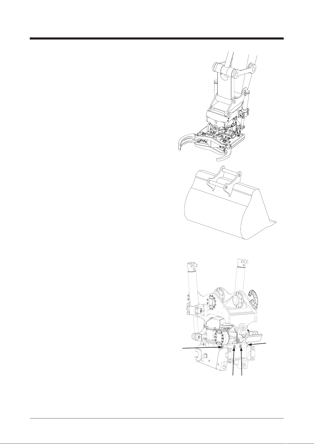
The QC quick coupler is tted with QuickChange
automatic hydraulic connections which enable
hydraulically-operated tools to be changed from the
driver’s cab. Note that tools must also be equipped
with QuickChange hydraulic connections.
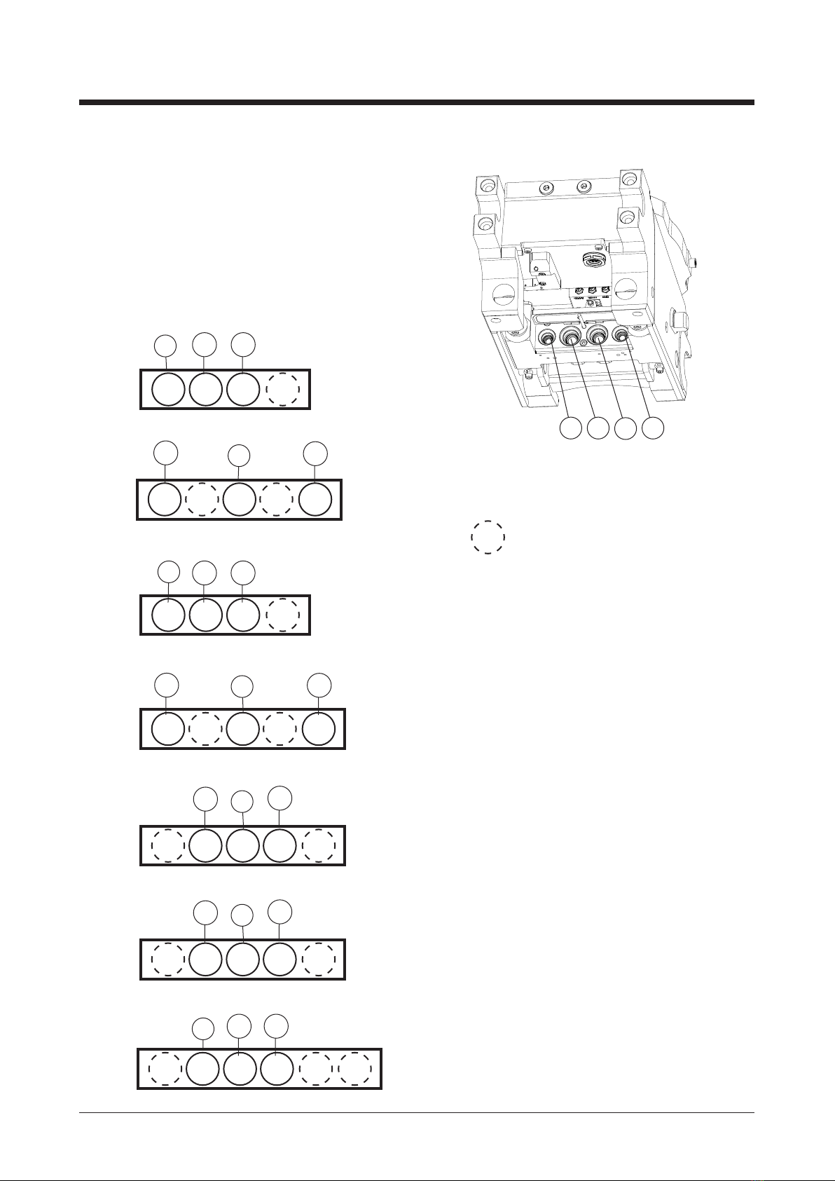
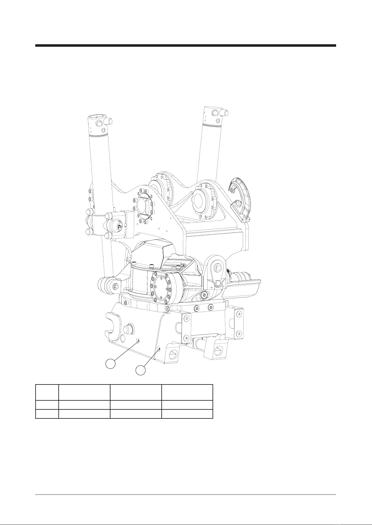
Function
The quick coupler consists of a quick coupler body
(pos. 1) and an H cylinder unit (pos. 2) with two
integral hydraulic cylinders, linked by two locking
pistons (pos. 3). The center section of the cylinder
unit has space for hydraulic quick connect ttings.
When the unit’s cylinders move, the quick coupler
locks and the hydraulics are connected simultaneously.
Connection and disconnection of tools and
hydraulics is done with the same cylinder movement.
The coupler is also tted with a mechanical dirt
protector (pos. 4) which stops dirt getting into
the quick connect ttings when using tools without
QuickChange quick hose connections.
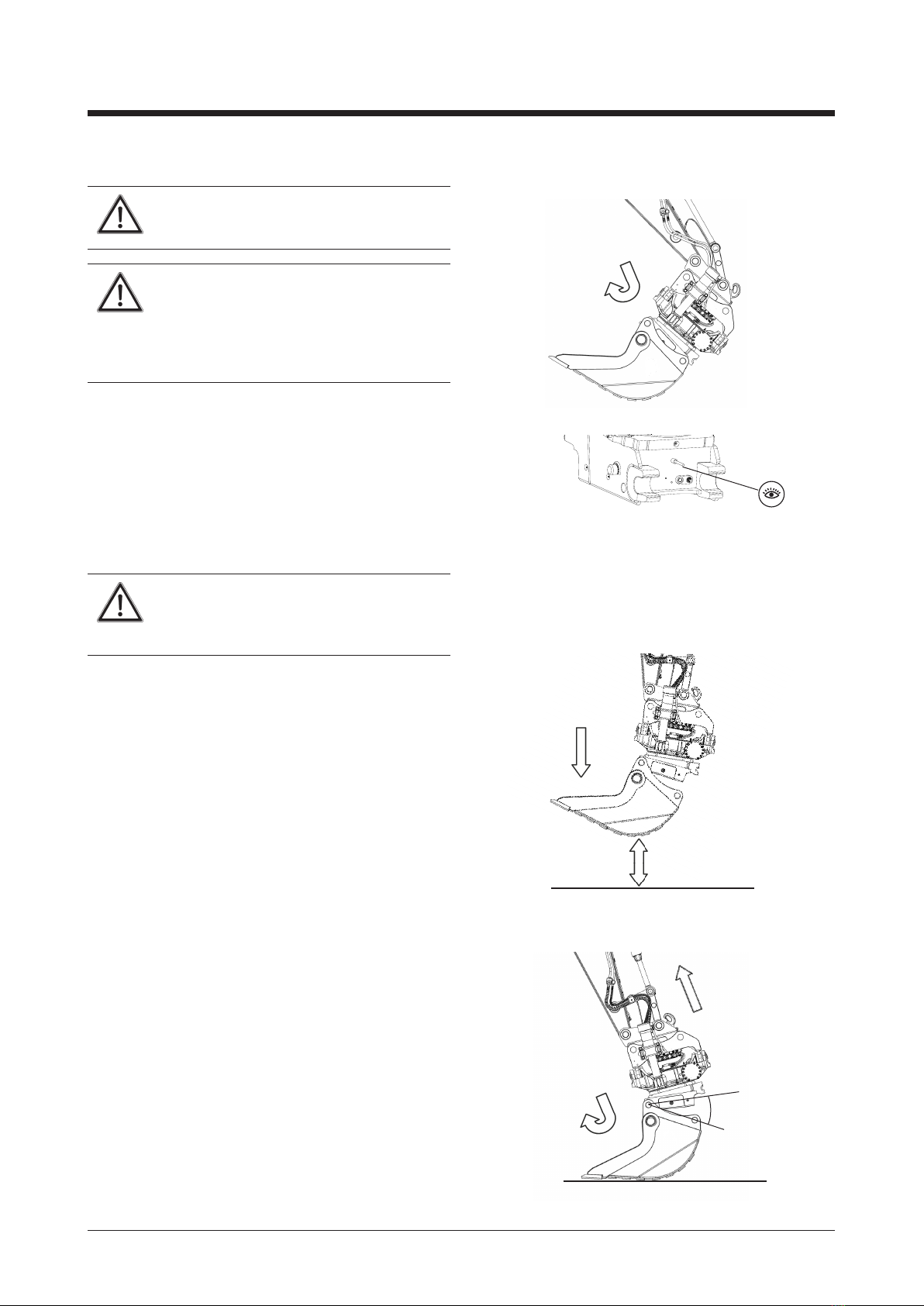
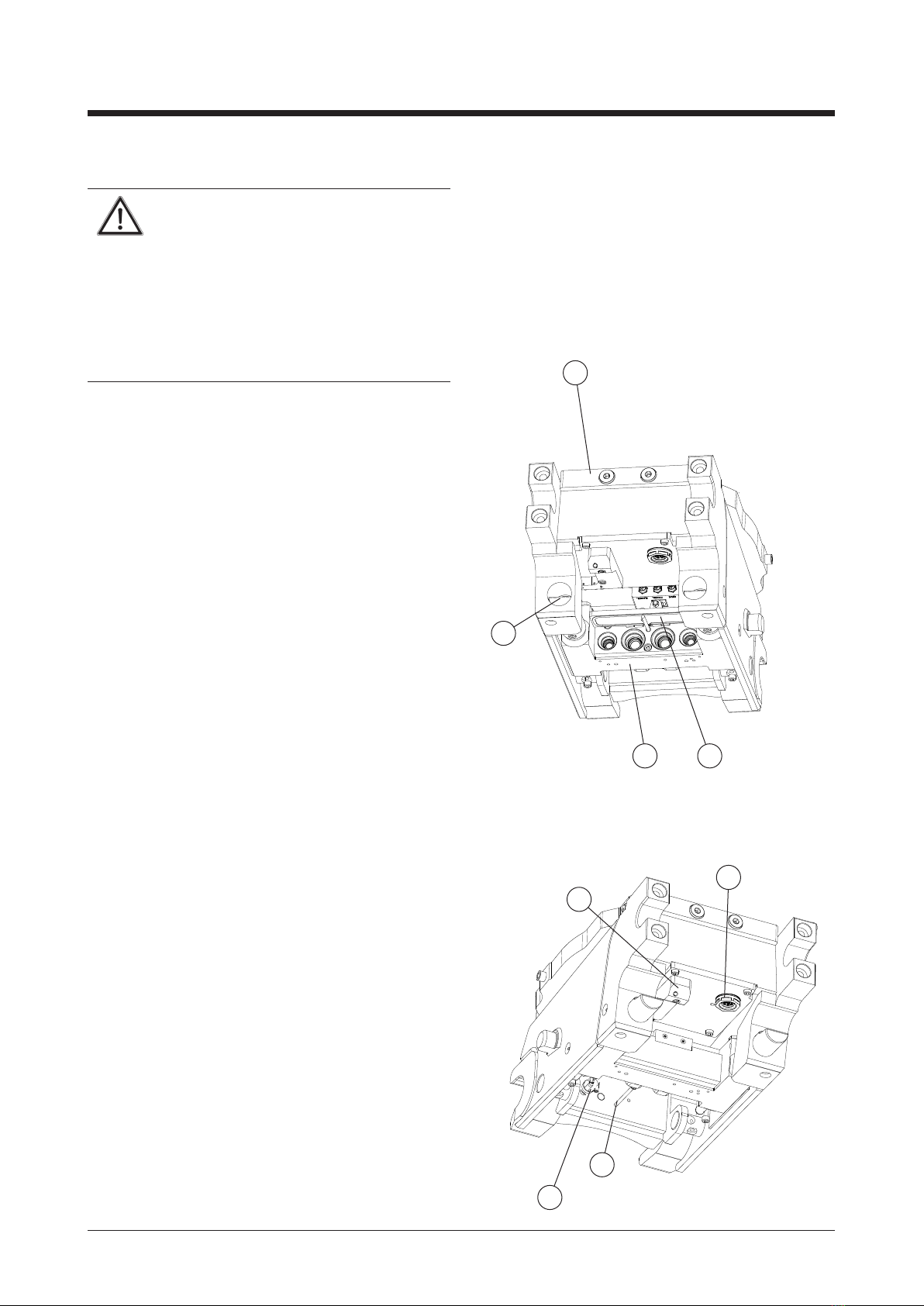
When the quick coupler locking function is in the
locked position without the QuickChange tool, the
cover that stops dirt getting into the quick connect
ttings will be closed. This closed position should
always be used if the machine has no tool attached.
Cylinder unit movement acts on the cover, which is
opened by a rod (pos. 5) xed to the quick coupler
frame.
Optional extras
The quick coupler can be tted with an optional
sensor (pos 6 and 7) to monitor the locking unit and/
or or an electrical plug (pos 8) to the tool connected.
Also refer to the Control system section.
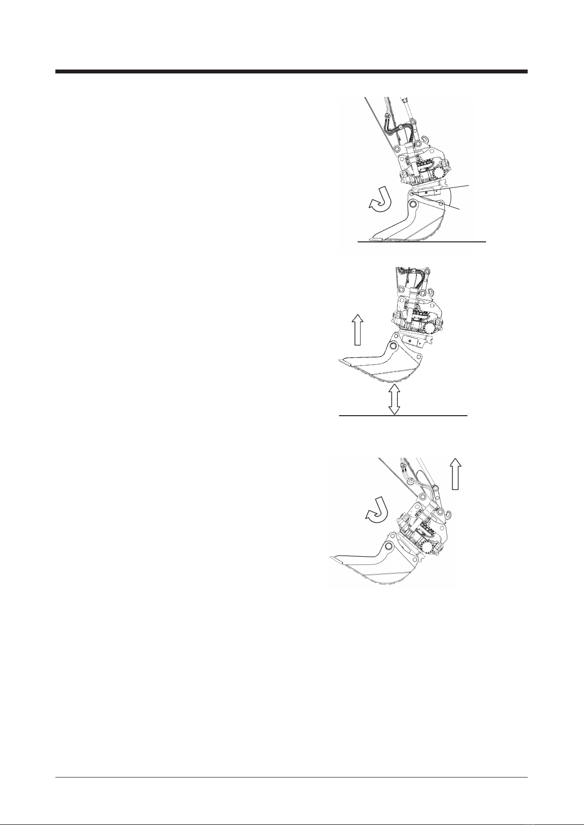
Figure 1.
Quick coupler locking
function open
Figure 2.
Quick coupler
locking function
closed

2200293 _5982 2016 05 02
4
3
21
4532
1
3/8"
3/8" 3/8"1/2" 1/2"
QC45-5
E2 /
HF LE2 /
HF
3 42
1
1/2"1/2"1/2" 1/2"
L
QC45
E2 /
HF
E2 /
HF
3 42
1
3/4"1/2" 1/2"3/4"
L
QC60
E2 /
HF
E2 /
HF
3 4 52
1
3/4"1/2" 1/2"1"1"
QC70 L
E2 /
HF
E2 /
HF
3 4 5 62
1
3/4" 3/4"1/2" 1/2"1"1"
L
QC70-55 / QC80
E2 /
HF
E2 /
HF
3 4 52
1
1/2"
3/4" 3/4"
3/8" 3/8"
QC60-5
E2 /
HF
E2 /
HF
L
3 4 52
1
3/4"1/2" 1/2"
QC65 L
E2 /
HF
E2 /
HF
3/4" 3/4"
English
EN
Quick connect ttings
QuickChange quick connect ttings are tted in the
center section of the H cylinder and are protected by
a cover.
The quick connect tting locations are shown below
with dimensions for the respective quick couplers
(Rototilt® standard).
Location seen from the locking cylinder side;
seegure4.
Figure 4. Quick coupler QC60
= Rototilt® standard without function

2200293 _5982 2016 05 02 English
EN
Connecting tools
This procedure assumes there is a tool attached
to the tiltrotator and that the quick coupler is in its
locked position.
• Check that nobody is present in the machine’s
working area.
• Open the quick coupler lock as described in
the Control system operation section.
• Make sure the indicator rod is visible (gure 8).
• Rotate the quick coupler so that the part furthest
away becomes visible. Check that the locking
cylinders are fully retracted (gure 9).
• Check that the quick coupler and the attachment
tting on the tool ready for connection are
properly in line (gure 10).
Figure 8
Figure 9
Figure 10
Correct Wrong

2200293 _5982 2016 05 02
30°-45°
English
EN
• Operate the tiltrotator to a position where the
quick coupler acquires an angle of 30°-45° in
relation to the tool’s attachment tting (gure 11).
• Hook the quick coupler’s forward attachment
onto the tool’s front shaft.
• Lift the tool from the ground so that it hangs
freely (gure 12).
• Operate the tiltrotator such that the quick
coupler’s rear part moves down toward
the tool’s rear shaft (gure 13).
• Connect the tool as described in the Control
system operation section. Any hydraulic or
electrical connections will be connected at
the same time.
• Make sure the indicator rod is not visible.
Figure 11
Figure 12
Figure 13
Approx 30 cm

2200293 _5982 2016 05 02 English
EN
Check, tool connection
Warning! The operator must always check
that the tool is locked according to the
description below. In case of doubt, the
tool must be disconnected and the cause
investigated. Refer to the Troubleshooting
section.
• Check that the locking cylinders have a proper
grip beneath the tool’s rear shaft. This can be
conrmed visually by rotating the quick coupler
so that the rear shaft of the connected tool
becomes a visible (see gures 14 and 15).
• As a test, operate a hydraulic function on the
hydraulic tool.
Figure 14
Figure 15
Figure 16
Correctly connected
Incorrectly connected
IMPORTANT! Checking the quick
coupler lock
Even if the indicator shows the locking
wedge to be in the locked position,
conduct the following checks to ensure
it is correctly secured:
- Press the tool against the ground,
(gure16). In this position, extend
and retract the bucket to check that
the locking wedge has locked the tool
correctly.
- Use the opportunity to rotate the
quick coupler and, from the operator’s
position, check the wedge is in its
locked position.
- If you are unsure whether or not the
tool is securely attached, exit the cab
and check that the locking wedge has
engaged.
- Do not operate the machine if the
quick coupler does not work correctly.
Contact your dealer immediately if you
detect faults.

2200293 _5982 2016 05 02 English
EN
Disconnecting tools
Important! Special requirements may
apply to individual tools. Read the tool
documentation in this regard.
DANGER! No one may be present
within the machine’s working area when
tools are connected, replaced or set
down. Tools may come lose or overturn
unexpectedly during the connection
procedure, causing injury or damage.
Procedure for disconnecting tools
• Check that nobody is present within the
machine’s working area.
• Lift the tool.
• Operate the tiltrotator so that the tool hangs by
its front shaft and press the rear shaft towards
the tool (see gure 17).
Important! It is extremely important
that the tool be tilted inward, otherwise
the tool may fall unexpectedly when
the coupler is opened.
• Open the quick coupler as per the Control
system section.
• Make sure the indicator rod is visible
(see gure 18).
• Operate the tiltrotator so that the tool is only
hanging by its forward shaft (see gure 19).
• Lower the tool to the ground. The ground must
be rm and even.
• Retract the bucket cylinder until the angle to
the quick coupler and the attachment is 30°-45°
(see gure 20).
• Free the front shaft from the attachment and
raise the boom.
• Lock the quick coupler according to the Control
system operation section.
• Check that the quick coupler is locked and that
the cover protecting the quick connect ttings is
closed.
Figure 17
Figure 18
Figure 19
Figure 20
approx 30 cm
30°-45°

2200293 _5982 2016 05 02 English
EN
Quick coupler with grapple module
Check that the tool used in combination with
Rototilt® does not interfere with the Grapple
module. (seegure21). In certain cases,
it may be necessary to adjust the tool.
Referalsotothegrapplemodule’sinstructions
foruse.
Extra grapple function
The extra function enables the use of a grapple
module with Rototilt®. It also controls the oil
ow to the connection nipples (gure 22).
Referalsotothegrapplemodule’sinstructions
foruse.
Figure 22
Figure 21

2200293 _5982 2016 05 02 English
EN
Maintenance
Regular inspections and maintenance are essential
to ensure good function and high reliability of the
QuickChange quick coupler system.
Daily checks
At the beginning of the day.
• The indicator rod must be retracted.
• The quick coupler and the tool attachment must
be kept free of snow and ice in winter.
• As necessary, hose or wipe away sand, ice and
snow. This is especially important in winter as
these may freeze solid and caused damage to
piston rods, connections and other quick coupler
components.
At the end of the day
• Perform the checks described under At the
beginning of the day.
• Check that the protective cover is working as
intended.
• Check that there are no leaks.
• The quick coupler and the tool attachment must
be kept free of snow and ice in winter.
• As necessary, hose or wipe away sand, ice and
snow. This is especially important in winter as
these may freeze solid and caused damage to
piston rods, connections and other quick coupler
components.
• Clean the quick connect ttings in the quick
coupler.
• Grease the locking cylinders and the side faces.
There are four grease nipples for this purpose.
• Clean the tool’s quick connect ttings
Monthly inspections
A more thorough inspection must be carried out
monthly.
Check that there is no play in the locking cylinders.
• Check that are no cracks in the quick coupler or
the tool.
Faults detected during inspections must be
remedied right away so as not to impair tiltrotator
function and reliability.

2200293 _5982 2016 05 02
1
2
English
EN
Quick coupler grease points
Quick coupler grease points are shown below.
The table lists a description of grease points,
their number and greasing frequency.
Pos Description Number of
lubrication points
Interval
1 Guide plane 2 Daily
2 Locking cylinders 2 Daily
Figure 23

2200293 _5982 2016 05 02
English
EN
H cylinder quick connect ttings
maintenance
Important! Protective gloves must be worn
when working with hydraulic oil to avoid
direct contact with the skin. There is a risk
of skin irritation and allergies. Protect and
care for the environment. Collect all waste
oil and clean up any spillage.
Important! Cleanliness is the rst priority
with all work on hydraulic systems. There
is a risk of malfunctions if contaminants
enter the system.
The quick connect ttings that connect the tool to the
machine wear and age with use. If they begin to leak
they must be overhauled or replaced. If the nose
seal leaks when the tool is connected and in use,
it is probably damaged and must be replaced.
If it leaks whether or not the tool is connected and
in use, the nose seal is probably damaged and must
be replaced.
Replacing the nose seal, quick connect tting
1. Remove the damaged nose seal.
2. Carefully clean around the seat of the tting.
3. Install the new nose seal with the aid of the special
pusher installation tool.
4. First insert the O-ring and then the support ring (with
the black marking facing up) into the pusher
tube (see gure 24). NOTE The tapered part of
the pusher tube (upper part) must face up. For
1/4" and 3/8" female connectors, see item 6
below.
NOTE! Insert to the O-rings rst and then
the support ring (does not apply to the 1/4"
and 3/8" female connectors). The black
side of the support ring must face the
pusher piston.
5. Female connectors, 1/2", 3/4" and 1": Feed the nose
seal into the pusher tube’s lower end by placing
the pusher on a table or other at surface and
then pressing the seal to the bottom with the aid
of the pusher piston (see gure 25).
Figure 24
Figure 25
Pusher piston
Support ring (black side up)
Pusher tube
O-ring

2200293 _5982 2016 05 02
English
EN
6. In the case of the 1/4" and 3/8" female connectors,
the support ring and the O-ring must be inserted
from the other end of the pusher tube (the end
furthest away) compared to gure 23.
NOTE! The support ring must be inserted rst,
black marking facing up toward the pusher,
followed by the O-ring. Then place the pusher on
a table or other at surface and press the seal
to the bottom with the aid of the pusher piston
(see gure 25).
7. Place the pusher against the female connector
and press rmly against the pusher piston.
See gure 26.
8. Make sure the nose seal is properly installed; (see
gure 27).
Figure 26
Figure 27

2200293 _5982 2016 05 02
1
2
7
6
5
4
3
English
EN
Replacing quick connect ttings secured
by locking rings
Parts included:
1. Hydraulic connector
2. Quick connect tting
3. Protective cover
4. Guide plate
5. Locking ring
6. Steel washer
7. Quick connect ttings seat
Procedure:
• Shut down the machine and relieve the pressure in the hydraulic system.
• Open the protective cover (3).
• Remove the guide plate (4).
• The locking ring (5) that retains the quick connect tting is now accessible. Remove and scrap the
locking ring and the steel washer (6) behind it.
• On 1" quick connect ttings fastened with screws, remove the screws and their washers and scrap them.
• Pull the quick connect tting out of the H cylinder.
• Undo the hydraulic connection (hydraulic hose/tube/adapter) (1) from the quick connect tting concerned (2).
• Scrap the quick connect tting.
• Reinstall the hydraulic connection on the quick connect tting.
• Clean and degrease the seat (7) in the age cylinder before installing a new quick connect tting.
• Fit new parts and reinstall the other parts concerned in reverse order.

2200293 _5982 2016 05 02 English
EN
Quick coupler troubleshooting
Wrong Reason Measure
Quick coupler cannot be close
Incorrectly performed tool attachment Check tool connection according
to the Control section
Hydraulic pressure in the lock circuit
is too low to close the quick coupler.
Check the pressure in the lock
circuit. If it is too low, check lock
valve function. If the lock valve is
serviceable, the fault lies with the
machine.
The protective cover does not
open and presses against the male
connectors. The rod that opens
the cover is missing.
Install a new rod.
One or more male connectors have
become skewed and no longer t
the female connectors.
Contact your dealer.
The quick coupler cannot be opened.
Hydraulic pressure in the lock circuit
is too low to close the quick coupler.
Check the pressure in the lock
circuit. If it is too low, check lock
valve function. If the lock valve is
serviceable, the fault lies with the
machine.
One of the two pilot-valve controlled
check valves in the H cylinder is
defective and will not open. Contact your dealer
Pressure relief valve defective
Oil leak from the quick connect ttings
when the tool is connected
The nose seal is missing or damaged.
Replace the nose seal as described in
the section Replacing the nose seal,
quick connect tting
The quick connect ttings are dirty
or damaged.
Clean or install new quick connect
ttings as described in the section
H cylinder quick connect ttings
maintenance.
Oil leak from quick connect tting The quick connect tting is dirty
or damaged
Clean or install new quick connect
ttings as described in the section
H cylinder quick connect ttings
maintenance.
The tool hydraulics to not function.
Incorrectly performed tool attachment. Check according to the section
Connecting and disconnecting tools.
The machine does not provide the
tool with the pressure and/or ow
it needs
Check the machine handbook or
contact the machine supplier.
Fault in the tool's hydraulic and/or
electrical systems.
Checked the tool's manual or contact
the tool supplier.
The tool's hydraulics and/or electrical
system does not function.
Defective electrical connection
between the toll and a quick coupler.
Check the harness and electrical
connections. Replace or repair
defective parts. Refer to the handbook
regarding electrical connections.

2200293 _5982 2016 05 02
6°
Attachment fitting
QC45 QC60 QC60-5 QC65 QC70 QC70-55 QC80
E430.25 ± 0.25 480.25 ± 0.25 480.25 ± 0.25 530.25 ± 0.25 600.25 ± 0.25 600.25 ± 0.25 670.25 ± 0.25
FMin 70 Min 85 Min 85 Min 115 Min 115 Min 115 Min 135
GMax. 45 Max. 60 Max. 60 Max 65 Max. 75 Max 75 Max. 90
HMax. 125 Max. 150 Max. 150 Max 150 Max. 250 Max250 Max. 250
I291.5 ± 0.5 341.5 ± 0.5 341.5 ± 0.5 441 +1/0 451.5 ± 0.5 551 +1/0 591.5 ± 0.5
JØ 45 f8 Ø 60 f8 Ø 60 f8 Ø 65 f8 Ø 70 f8 Ø 70 f8 Ø 80 f8
KMax. 520 Max. 600 Max. 600 Max. 660 Max. 740 Max. 750 Max. 830
LMax. F Max. F Max. F Max. F Max. F Max. F Max. F
English
EN
The quick coupler attachment is offset 6°to the tool
ready for connection under Rototilt® (gure 30).
Dimensions
Connected tools and implements should meet
the dimensions below.
Figure 29
Figure 30

2200293 _5982 2016 05 02 English
EN
Hydraulics diagram, quick coupler
locking function
This manual suits for next models
6
Table of contents
Other ROTOTILT Construction Equipment manuals