HADEF EEE Assembly instructions

5.52.707.00.01.02 Rev.02
Pos:1.1 /1_HADEF/---TITELSEITE/Symbole/Ländersymbol @ 0\mod_1171286564146 _52.docx @ 55 @ @ 1
Pos:1.2 /1_HADEF/---TITELSEITE/Allgemein/Titel- BA@ 0\mod_1171286931725_52. docx @ 57 @ @1
Pos:1.3 /1_HADEF/---TITELSEITE/Allgemein/HADEF-Bezeichnung@ 0\mod_117128 9923124_0.docx @ 69 @ @ 1
HADEF Single Girder Electric Overhead Travelling
Crane
Type EEE
Pos:1.4 /1_HADEF/---TITELSEITE/Bauarten/auch alsAdapterkran@ 2\mod_1288102918176_52. docx @ 16586 @ @ 1
also available as adapter crane
^
Pos:1.5 /1_HADEF/---TITELSEITE/Bauarten/leer-Standard @ 0\mod_1172062835772 _52.docx @ 201 @ @ 1
Pos:1.6 /1_HADEF/---TITELSEITE/Bauarten/leer-Standard @ 0\mod_1172062835772 _52.docx @ 201 @ @ 1
Pos:1.7 /1_HADEF/---TITELSEITE/Abbildung/EEE@ 1\mod_1238406962 609_0.docx @ 9700 @ @ 1
Installation,- Operating and
Maintenance Instructions

2 5.52.707.00.01.02
Pos:2 /1_HADEF/---ALLGEMEIN/Allgemein/2.unvollständige Maschine/HINWEIS- unvollständige Masch. -Montagean leitung @ 1\mod_1260449997 342_52.docx @ 11373 @ @ 1
NOTICE!
The installation or mounting instructions for incomplete machines you’ll find in chapter “Installation”
Pos:3 /1_HADEF/---ALLGEMEIN/Allgemein/3.Copyright/Copyrightf. BA's (mit Download link) @ 0\mod_1171286454687_5 2.docx @ 54 @ @ 1
o
©by Heinrich de Fries GmbH
Heinrich de Fries GmbH, Gauss Str. 20, D-40235 Düsseldorf
Heinrich De Fries GmbH will be named HADEF in the following text.
Original operating- and maintenance instructions in German language.
Translation in other languages is made of the German original.
A copy may be requested in writing or is available for download on www.hadef.com
Subject to changes.
Pos:4 /1_HADEF/---ALLGEMEIN/Allgemein/4.Inhaltsverzeichnis/InhaltsverzeichnisÜ1-2@ 0\mod_1171286846268_ 52.docx @ 56 @ @ 1
Table of Contents
1Information..........................................................................................3
1.1Indications to determine the used part of the theoretical usage life............................4
2Safety...................................................................................................4
2.1Warning notice and symbols............................................................................................4
2.2Duty of care of the owner..................................................................................................4
2.3Requirements for the operating personnel.....................................................................5
2.4Appropriate use.................................................................................................................5
2.5Basic safety measures......................................................................................................6
3Transport and Storage.......................................................................6
3.1Transport............................................................................................................................6
3.2Safety device for transport...............................................................................................6
3.3Storage ...............................................................................................................................7
4Description..........................................................................................7
4.1Areas of application ..........................................................................................................7
4.2Design.................................................................................................................................7
4.3Function description.........................................................................................................8
4.4Important components......................................................................................................8
5Technical data.....................................................................................9
6Installation...........................................................................................9
6.1Assembly - for complete cranes ......................................................................................9
6.2Assembly - partially assembled cranes.........................................................................10
6.3Assembly - Adapter Cranes............................................................................................10
6.4Srew connection..............................................................................................................11
6.1Tools.................................................................................................................................11
7Operation...........................................................................................11
8Operation...........................................................................................12
9Commissioning.................................................................................12
9.1General .............................................................................................................................12
9.2Electrical connection.......................................................................................................13
9.3Gear...................................................................................................................................13
10Safety check......................................................................................13

5.52.707.00.01.02 3
11Functional test.................................................................................. 14
11.1Checks before initial start-up.........................................................................................14
11.2Functional test.................................................................................................................14
12Maintenance...................................................................................... 14
12.1General.............................................................................................................................14
12.2Monitoring........................................................................................................................14
12.3Brake motor .....................................................................................................................14
13Inspection ......................................................................................... 15
13.1General Overhaul for motor-driven units......................................................................15
13.2Periodic checks...............................................................................................................15
13.3Inspection intervals.........................................................................................................15
14Service............................................................................................... 16
14.1Crane trolley ....................................................................................................................16
14.2Lubricant selection .........................................................................................................16
14.3Lubricant for food industry – selection (as option*)....................................................16
15Trouble .............................................................................................. 16
16Remedy ............................................................................................. 17
17Decommissioning ............................................................................ 18
17.1Temporary decommissioning ........................................................................................ 18
17.2Final decommissioning/disposal...................................................................................18
18Additional documents...................................................................... 18
18.1Electric wiring diagram...................................................................................................18
18.2Frequency converter.......................................................................................................18
18.3Radio control ...................................................................................................................18
18.4Operating instruction for cranes....................................................................................18
Pos: 5.1 /1_HADEF/1-- INFORMATION/*Ü1*/ #.Kapitel - Informatio n @ 0\mod_1174470941082_5 2.docx @ 811 @ @ 1
1 Information
Pos: 5.2.1 /1_HADEF/1- -INFORMATION/Allg emein/*Information* /01.Information @ 0\mod_1176734820982_52.doc x @ 4653 @ @ 1
The products meet European Union requirements, in particular the valided EU Machine Directive.
The entire company works acc. to a certified quality assurance system as per ISO 9001.
The production of components at our work is subject to strict, intermediate checks.
After assembly, each product is subject to a final test with overload.
For the operation of hoists, the national accident prevention regulations apply in Germany, amongst others.
The stated performance of the devices and meeting any warranty claims require adherence to all instructions
in this manual.
Before delivery, all products are packed properly. Check the goods after receipt for any damage caused
during transport. Report any damage immediately to the forwarding agent.
This manual allows a safe and efficiently use of equipment. Images of this manual are for a principle
understanding and can be different from the real design.
Pos:5.2.2 /1_HADEF/---ALLGEMEIN/Hinweise/Prüfungen/HINWEIS- VorgeschriebenePr üfungen @ 0\mod_117447206 7892_52.docx @ 821 @ @ 1
NOTICE!
We refer to the prescribed equipment tests before initial start-up, before putting back into operation and the
regular periodic inspections.
In other countries any additional national regulations must be observed.
Pos: 5.3.1 /1_HADEF/1- -INFORMATION/Allg emein/*Hinweise the or.Nutzung -E+P*/ 02.Hinweise theor. Nutzu ng @ 0\mod_117577643436 6_52.docx @ 3429 @ @ 1

4 5.52.707.00.01.02
1.1 Indications to determine the used part of the theoretical usage life.
For motor driven units.
The equipment (rope hoists, chain hoists, winches as well as crane hoisting units) are classified in drive
groups (duty classification) according to their intended mode of operation, running times and load collectives
and dimensioned according to the requirements derived from these.
They are thus only designed for a limited period of use with regard to the overall dimensioning and
certification.
After the total period of use as elapsed, measures must be taken where parts are checked and exchanged
as per indication by the manufacturer. After that a new maximum usage period is determined. See also the
valued accident prevention regulations, “winches, lifting and pulling devices”.
Pos:5.3.2 /1_HADEF/---ALLGEMEIN/Hinweise/HINWEIS- Generalüber holung nur durch Hadef @ 0\ mod_1176794916616_52. docx @ 4672 @ @ 1
NOTICE!
Commitment
A general overhaul may only be performed by HADEF or by a specialized company, authorized by HADEF.
Pos: 6.1 /1_HADEF/2-- SICHERHEIT/*Ü1*/ #. Kapitel - Sicherhei t@ 0\ mod_1172054959462_52.d ocx @ 172 @ @ 1
2 Safety
Pos: 6.2.1 /1_HADEF/2- -SICHERHEIT/Allge mein/Warnhinweise + Sy mbole/01.Warnhi nweise + Symbole @ 0\mod_11720505 13996_52.docx @ 165 @ @ 1
2.1 Warning notice and symbols
Warnings and notice are shown as follows in these instructions:
DANGER! This means that there is a high risk that leads, if it is not avoided, to death or severe injury.
WARNING! This means that there is a risk that could lead, if it is not avoided, to death or severe injury.
CAUTION! This means that there is little
risk that could lead, if it is not avoided, to slight injury or damage to the device or its
surrounding.
NOTICE! Gives advice for use and other useful information.
Danger from electricity.
Danger from explosive area.
Pos: 6.2.2.1 /1_HADEF/ 2--SICHERHEIT/A llgemein/Sorgfalts pflicht des Betreiber s/04.Sorgfaltspf licht des Betreibers @ 0\mod_1172050137593_52.doc x @ 162 @ @ 1
2.2 Duty of care of the owner
The unit was designed and built following a risk analysis and careful selection of the harmonized standards
that are to be complied with, as well as other technical specifications. It therefore represents state-of-the-art
technology and provides the highest degree of safety.
Our delivery includes the hoist supplied beginning at its suspension and ending at the load hook and if
supplied with control, the control line/hose that leads to the hoist. Further operating material, tools, load
attaching devices as well as main energy supply lines must be assembled according to the valid rules and
regulations. For explosion-proof equipment, all these parts must be approved for use in area prone to
explosion, or they must be suitable for use in area prone to explosion. The owner is responsible for this.
However, in everyday operation this degree of safety can only be achieved if all measures required are
taken. It falls within the duty of care of the owner/user of the devices to plan these measures and to check
that they are being complied with.
Complete the operating and installation instructions by any instructions (regarding supervision or
notifications)that are important for the special kind of use of the equipment, i.e. regarding organization of
work, work flow and human resources.
In particular, the owner/user must ensure that:
The unit is only used appropriately.
The device is only operated in a fault-free, fully functional condition, and the safety components, in
particular, are checked regularly to ensure that it is functioning properly.
The required personal protective equipment for the operators, service and repair personnel is available
and is used.

5.52.707.00.01.02 5
The operating instructions are always available at the location where the equipment is used and that they
are legible and complete.
The unit is only operated, serviced and repaired by qualified and authorized personnel.
This personnel is regularly trained in all applicable matters regarding safety at work and environmental
protection, and that they are familiar with the operating manual and, in particular, the safety instructions it
contains.
Any safety and warning signs on the devices are not removed and remain legible.
Devices for use in area prone to explosion must (from customer's side) be earthed with a shunting
resistor of < 106Ωagainst earth.
Pos:6.2.2.2 /1_HADEF/---ALLGEMEIN/Hinweise/WARNUNG - Keine konstuktiven Änderungen @ 0\mod_117679 7173443_52.doc x @ 4704 @ @ 1
WARNING!
It is not allowed to make constructive changes of the equipment!
Pos: 6.2.3 /1_HADEF/2- -SICHERHEIT/Allge mein/Anforderungen an da s Bedienpersonal/05. Anforderungen an da s Bedienpersonal @ 0\mod_11 72055544978_52.doc x @ 179 @ @1
2.3 Requirements for the operating personnel
The units may only be operated by qualified persons that are appropriately trained and that are familiar with
it. They must have their employer’s authorisation for operation of the units.
Before starting work, the operating personnel must have read the operating and installation instructions,
especially the chapter "Safety Instructions".
This is especially important for operating personnel that rarely uses the equipment, i.e. for installation or
maintenance work.
DANGER!
In order to avoid severe injury, please pay attention to the following when using the equipment:
Use protective clothes/equipment.
Do not wear long hair hanging down open.
Do not wear rings or other jewellery.
Do not wear clothes that are too big/wide.
Pos: 6.3 /1_HADEF/2-- SICHERHEIT/Bestim mungsgemäße Verwendung/01. Alle (außer 380) @ 2\ mod_1300955165911_52. docx @ 18464 @ @ 1
2.4 Appropriate use
The permitted safe working load of the devices must not be exceeded! An exception can be made during the
load test before initial operation, carried out by a licensed qualified person.
The permissible ambient temperature during operation of manual driven devices is -20 ° C / + 50 ° C and
at all power driven devices -20 ° C / + 40 ° C!
Defective devices and load suspension devices must not be used until they have been repaired! Only
original spare parts must be used. Non-compliance will result in any warranty claims becoming void.
Liability and warranty will become void if unauthorized modifications of the units are made by the user!
Pos: 6.4 /1_HADEF/2-- SICHERHEIT/Bestim mungsgemäße Verwendung/08. Alle Laufkrane @ 2\mod_13009 56454440_52.doc x@ 1849 2 @ @1
Horizontal movement of loads in direction of the beam and crane runway. The cranes can be used with
suitable lifting gears.
Pos:6.5 /1_HADEF/---ALLGEMEIN/Hinweise/HINWEIS- BestimmungsgemäßeVerwendung - Personen+ Sachschäden @ 0\mod_11767 99465432_52.doc x @ 4749 @ @1
NOTICE!
If the units are not used appropriately, it is not possible to ensure safe operation.
The owner and operator have sole liability for all personal injury and damage to property arising from
inappropriate use.
Pos:6.6 /1_HADEF/---ALLGEMEIN/Hinweise/GEFAHR- Losreißen,Personentr.,schweb.Lasten, exverboten(E+P) @ 0\mod_1176799462104_52. docx @ 4735 @ @ 1
DANGER!
It is not allowed:
pulling loose of stuck loads, dragging of loads and inclined pulling is not allowed.
in explosive atmosphere, except the unit is especially modified for it and marked by an indication label
to transport people
The device is not suitable for use on stages and in studios
persons must not stand under a suspended load
Pos: 6.7 /1_HADEF/2-- SICHERHEIT/Grundle gende Sicherheitshin weise/1.Alle (außer 380)@ 2\ mod_1300886479193_52. docx @ 18426 @ @ 1

6 5.52.707.00.01.02
2.5 Basic safety measures
Observe installation-, operation and maintenance instruction.
Take notice of caution notes at units and in the manual
Observe safety distances.
Take care for a free view on the load.
Only use the hoists appropriately.
The equipment is to be used exclusively for movement of goods. Under no circumstances my persons be
moved.
Never load the devices beyond their working load limit.
Pay attention to the accident prevention regulations (UVV).
Should the hoist be used outside of Germany, please pay attention to the national regulations that apply.
Supporting structures and load-attached devices used in conjunction with this equipment must provide an
adequate safety factor to handle the rated load plus the weight of the equipment. In case of doubt, consult
a structural engineer.
If the equipment has not been used for a period of time, carry out visual checks of all main components
such as chains, load hooks etc. and replace any damaged parts with new, original spare parts before
putting the equipment back into operation!
Do not use a hoist that is defective, pay attention to any abnormal noise it makes during operation.
Stop working immediately in case of disturbances and remedy failures.
Any damage and faults must be reported to a responsible supervisor immediately.
If the unit is put into motion, any persons in the immediate vicinity must be informed by calling to them!
Please pay attention to the regulations for load carrying devices UVV for both positive and non-positive
methods of attaching loads.
The lifting tackle or the load must be securely attached to the hook and be seated at the bottom of the
hook.
The safety catch of hooks must be closed.
When charged, the housing may not be in contact somewhere.
Pos: 6.8 /1_HADEF/2-- SICHERHEIT/Grundle gende Sicherheitshin weise/7.Alle Krane @ 2\ mod_1300889024587_52. docx @ 18446 @ @ 1
Observe separate installation-, operation and maintenance instruction of hoists.
Please consider oscillation of the load and stopping distance.
Make sure that the device stands stable.
Pos: 7.1 /1_HADEF/3--TRANSPORT/LAGERUNG/*Ü1*/#. Kapitel - Transport und Lagerung @ 0\ mod_1172058584305_52. docx @ 190 @ @ 1
3 Transport and Storage
Pos:7.2 /1_HADEF/---ALLGEMEIN/Hinweise/VORSICHT- Transport,Lagerung: nicht sachgemäß - keine Haf tung @ 0\mod_1176819827 794_52.docx @ 4910 @ @ 1
CAUTION!
Transport may only be done by qualified personnel. No liability for any damage resulting from improper
transport or improper storage.
Pos: 7.3 /1_HADEF/3--TRANSPORT/LAGERUNG/ Transport und Lagerung/ Transport und Lagerung @ 0\mod_1 172060037462_52.d ocx @ 194 @ @ 1
3.1 Transport
The devices are checked and if so adequately packed before delivery.
Do not throw or drop the equipment.
Use adequate means of transport.
Transport and means of transport must be suitable for the local conditions.
3.2 Safety device for transport
NOTICE!
Should a safety device for transport exist, please remove it before commissioning.

5.52.70
7
3.3
Stor
e
Prot
e
Prot
e
Pos: 8.1 /1_HADEF/4--BESC HREIBUNG/*Ü1*/#.Kapitel - Besc hreibung @ 0\mod
_
4
Pos: 8.2.1.1 /1_HADEF/4-- BESCHREIBUNG/Allgemein/ Anwendungsberei che/1.A
n
4.1
The dev
If they a
sunshin
e
continu
o
endang
e
A
mbien
t
not und
e
Pos: 8.2.1.2 /1_HADEF/4-- BESCHREIBUNG/Allgemein/ Anwendungsberei che/2.Zu
During l
o
Pos:8.2.1.3 /1_HADEF/---ALLGEMEIN/Hinweise/EX-Schutz/GEFAHR- Einsatzin
I
t
Pos: 8.3.1.1 /1_HADEF/4--BESC HREIBUNG/Krane/Aufbau/1. EHH+EEE+EDD @
4.2
HADEF
with any
trolley.
A
ccordi
n
Electric
a
H2/B3
Manual
C
A
s stan
d
end car
r
Optional
assembl
advand
a
Pos: 8.3.1.2 /1_HADEF/4--BESC HREIBUNG/Krane/Aufbau/2. Adapter krane-
A
lle
@
4.2.1
A
dapter
The mai
Pos: 8.3.1.3 /1_HADEF/4--BESC HREIBUNG/Krane/Aufbau/3. Adapter krane-
A
lle
@
The end
Pos: 8.3.2 /1_HADEF/4--BESC HREIBUNG/Krane/Funktion sbeschreibung/EEE @
2
7
.00.01.02
Storage
e
the equipm
e
ct the equip
e
ct hooks, wi
_
1172065358380_52. docx @ 215 @ @1
Descrip
n
wendungsbereic he - Alle (außer 380) @ 2\mod_1291 022296255_52.doc x@ 17584@ @ 1
Areas of
a
ices must b
e
re used in t
h
e
, dust, etc
.
o
usly humid
e
red by the f
o
t
temperatur
e
e
r water
u
satz E+P @ 0\mod_117206731617 4_52.docx @ 232 @ @ 1
o
nger period
EX verboten @ 0\mod_117687 8631716_52.doc x@ 49 40 @ @1
DAN
t
is not perm
2\mod_1287474539264_5 2.docx @ 16380 @ @ 1
Design
single-girde
r
y
type of HA
D
n
g to DIN 15
0
a
nd Pneum
a
C
ranes acc
o
d
ard, the cra
n
r
iage, versio
n
l
ly Version "
A
l
e the end c
a
a
geous.
@
2\mod_1288082417896_5 2.docx @ 16570 @ @ 1
Adapter C
cranes are
s
n beam can
@
2\mod_1290678435939_5 2.docx @ 17350 @ @ 1
carriages a
r
2
\mod_1287478115785_ 52.docx @ 16383 @ @ 1
ent at a cle
a
ment agains
re ropes, ch
a
tion
a
pplicatio
n
e
as far as p
o
h
e open, pr
o
.
- we reco
m
environm
e
o
rming of co
e
-20°C up t
o
s of standsti
GER!
itted to use
t
r
bridge cran
D
EF hoist co
0
18
a
tic Cranes
a
o
rding to H1/
n
es are sup
p
n
"C".
A
or B" can
b
a
rriage shoul
ranes
s
upplied wit
h
be bought n
r
e available
i
a
n and dry pl
a
t dirt, humid
i
a
ins and bra
n
o
ssible insta
l
o
tect the uni
t
m
mend to
u
e
nt with st
r
ndensation.
o
+50°C. Po
w
ll, corrosion
he unit in an
es can be u
s
m
bined with
a
ccording to
B
2
p
lied with w
e
b
e taken to
d this be m
o
h
out main be
earby the si
t
i
n two versi
o
a
ce.
i
ty and dam
a
a
kes against
l
led in a cov
e
t
s against th
u
se a cove
r
r
ong tempe
r
wer-operate
d
may reduce
n
area at risk
s
ed
e
lded
o
re
am.
t
e and asse
m
o
ns - with sc
r
a
ge by an a
p
corrosion.
e
red room.
e effects of
r
in parking
r
ature fluct
u
d
units -20
u
the function
from explos
Illustration
Illustration
Illustration
m
bled there
w
r
ew fittings o
r
propriate co
v
w
eather su
c
position. If
u
ations, the
u
p to +40°C.
of the brak
e
ion!
1
V
e
2
Version
A
3
w
hich reduc
e
r
weldable.
ver.
c
h as rain, h
a
the device
e
correct f
u
Humidity 1
0
e
.
e
rsion C
A
e
s costs for
t
a
il, snow, di
r
is set up i
n
u
nctionings
0
0 % or less
Version
B
t
ransport.
7
r
ect
n
a
are
but
B

8 5.52.707.00.01.02
4.3 Function description
Directions of movement
1 electrically trolley driving
2 electrically crane driving
3 electrically lifting and lowering
Illustration 4
Pos: 8.3.3.1 /1_HADEF/4-- BESCHREIBUNG/Krane/W ichtige Bauteile/EEE+EHH+EDD @ 2\ mod_1287482028042_52. docx @ 16386 @ @ 1
4.4 Important components
Main beam
Profiled steel beam
End Carriage
Structural tubing shape including running wheels and travel drive
▫Standard as welded version "C"
▫As option available with screw fittings, version "A+B"
Wheels
Machined, steel wheels with ball bearing and wheel flange
Pos: 8.3.3.2 /1_HADEF/4-- BESCHREIBUNG/Krane/W ichtige Bauteile/Zusat z für Elektro @ 2\mod_12892 13999920_52.docx @ 16614 @ @ 1
Drive
▫3-phase current motor
Electrical control
▫Contactor control or radio control by frequency converter for step less driving speed
Lifting unit and power supply
See separate instruction
Pos: 9.1 /1_HADEF/5-- TECHNISCHE DATEN/*Ü1*/ #. Kapitel - Technische Da ten @ 0\mod_1172067180778 _52.docx @ 229 @ @ 1

5.52.707.00.01.02 9
5 Technical data
Pos: 9.2 /1_HADEF/5-- TECHNISCHE DATEN/Krane/EEE/EEE @ 2\ mod_1287490269266_52.doc x @ 16396 @ @ 1
Capacity Span
up to Wheel base Max. wheel load
with hoist
Type 66/04
Max. wheel load
with hoist
Type 29/06
Wheel
Ø Stepless trolley
drive
from….to
Motor power
2x
Weight*
ca.
kg mm mm kg kg mm m/min kW kg
1000
7000 1200 692 705 125
0,5 – 20
or
0,5 - 40
0,37 744
9000 1200 788 801 125 0,37 1077
12000 1600 968 981 160 0,37 1858
15000 2200 1214 1227 200 0,37 2813
17000 2200 1383 1398 200 0,37 3279
18000 2500 1556 1571 250 0,55 4065
20000 2500 1735 1750 250 0,55 4773
2000
7000 1200 1222 1245 125 0,37 903
9000 1200 1314 1337 125 0,37 1184
12000 1600 1553 1576 160 0,37 2059
14000 2200 1717 1740 200 0,37 2681
16000 2200 1921 1945 200 0,37 3474
18000 2500 2204 2229 250 0,55 4588
20000 2500 2316 2341 250 0,55 5163
3200
7000 1200 1805 1907 160 0,37 1005
9000 1200 1970 2072 160 0,37 1510
12000 1600 2188 2290 160 0,37 2248
13000 2200 2307 2409 200 0,37 2694
16000 2200 2585 2687 200 0,37 3732
18000 2500 2807 2705 250 0,55 4588
20000 2500 2988 3090 250 0,55 5288
5000
7000 1600 2777 2795 160 0,37 1283
11000 1600 3116 3134 200 0,37 2236
12000 1600 3173 3191 200 0,37 2405
16000 2200 3596 3614 200 0,37 3940
18000 2500 3833 3851 250 0,55 4831
20000 2500 4025 4043 250 0,55 5548
6300
7000 1600 3390 3408 200 0,37 1353
10000 1600 3671 3689 200 0,37 2064
12000 1600 3845 3863 200 0,37 2602
14000 2200 4060 4078 200 0,37 3345
17000 2500 4405 4423 250 0,37 4603
18000 2500 4530 4548 250 0,55 5074
20000 2500 4747 4765 250 0,55 5891
10000
6000 1600 5126 5228 250 0,55 1704
9000 1600 5500 5488 250 0,55 2361
11000 1600 5714 6016 250 0,55 2915
12000 2200 5841 6143 315 0,75 3311
14000 2200 6077 6379 315 0,75 4079
15000 2500 6186 6488 315 0,75 4437
18000 2500 6632 6934 315 0,75 6058
20000 2500 6944 7246 315 0,75 7221
*Weights without lifting unit and standard profile
Listed data are standards. Intermediate sizes possible.
Pos: 9.3 /1_HADEF/5-- TECHNISCHE DATEN/Allgemei n/E-Motor/400V Motor @ 3\ mod_1378727800377_52.d ocx @ 27382 @ @1
3-phase current motor 400V/50Hz - IP55 – F – max. 1000 m above sea level.
Order-related Special data, refer to the motor nameplate.
Pos: 10.1 /1_HADEF/6- -MONTAGE/*Ü1*/#. Kapi tel - Montage @ 0\mod_1172127 582099_52.doc x@ 255 @ @ 1
6 Installation
Pos: 10.2.1 /1_HADEF/ 6--MONTAGE/Allgemei n/01.Krane - alle (außer 380)@ 2\mod_1287066709326_52.doc x@ 162 13 @ @1
Assembly depends on the local environment. The crane must be assembles stress-free. The runway must
be perfect.
Operating regulations for cranes in accordance with the validated accident prevention regulations.
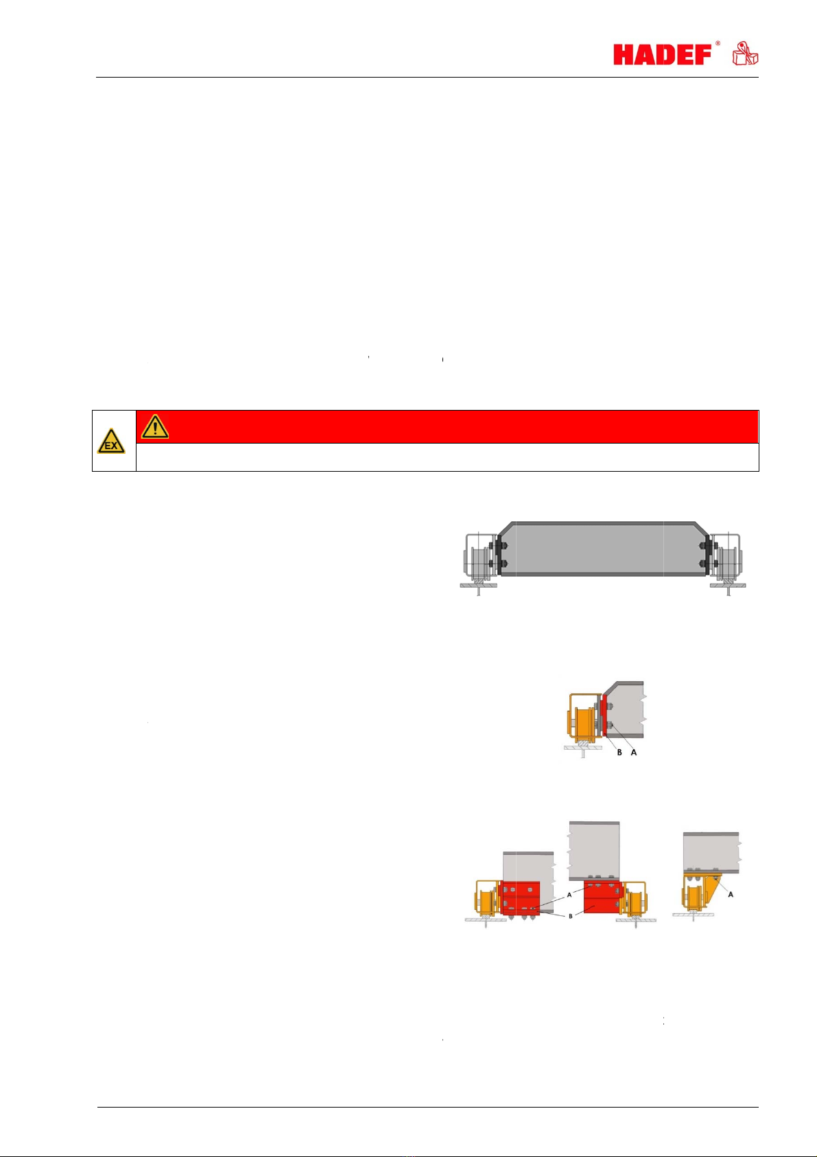
There must be end stops (provided by the customer) on both ends of the crane runway.
They must be attached so that the rubber buffers or the trolley wheels drive against them in their end
position.
Generally, additional lifting gear (e.g. fork lift, lifting platforms) will be required for the assembly.These must
take the weight of the devices safely.
Pos: 10.3.1 /1_HADEF/6- -MONTAGE/Krane/EEE+EHH+EDD/ 1 Komplettkran @ 2\mod_1287 496814822_52.doc x@ 164 03 @ @1
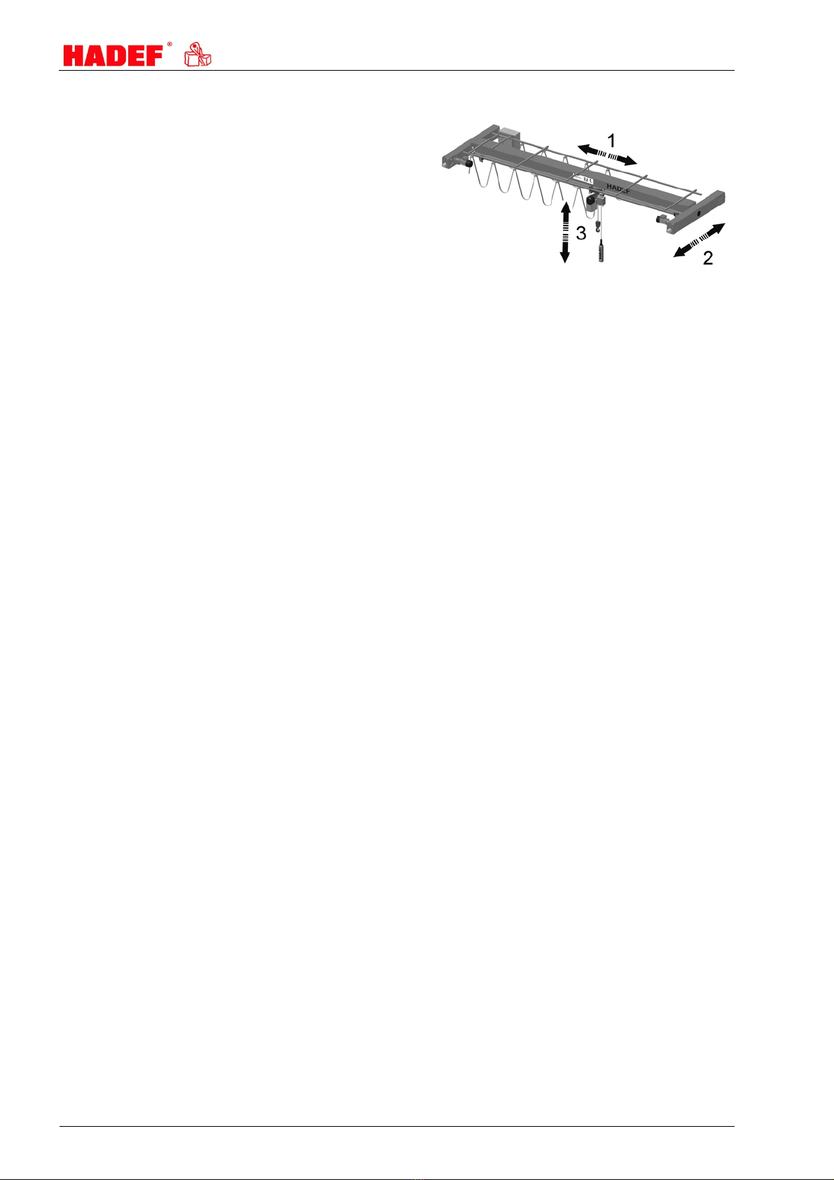
6.1 Assembly - for complete cranes
The crane is fully assembled and installed, including the hoist and power supply for the electric or pneumatic
version.
It only needs to be placed on the crane way with a suitable lorry mounted crane.

10
Pos: 10.3.2 /1_HADEF/ 6
-
6.
2
Th
cr
a
in
s
Pos: 10.3.3 /1_HADEF/ 6
-
6.
3
S
c
Pos: 10.3.4 /1_HADEF/ 6
-
A
B
1.
2.
3.
4.
Prepare cr
a
transport w
i
Set the cra
n
are resting
o
beam.
The wheel
f
wheels mu
s
crane rail -
d
For motor-
d
must effect
according t
o
-MONTAGE/Krane/EEE+E HH+EDD/2 teilmontierter Kr an @ 2\mod_1287497702640_5 2.docx @ 16406 @ @ 1
2
Ass
e
e crane is,
a
a
nes. Befor
e
s
tructions fo
r
Install the h
instructions
Assemble
m
the wiring d
Proceed as
complete c
r
-MONTAGE/Krane/EEE+E HH+EDD/3 Adapterkran @ 2\mod_128808 6108867_52.doc x@ 16576 @ @ 1
3
Ass
e
c
ope of supp
l
1 set end c
a
1 set adapt
e
fastening d
e
1 set welda
-MONTAGE/Krane/EEE+E HH+EDD/4 Adapter A+B+C @ 2\mod_128808 7442675_52.docx @ 16579 @ @ 1
Fastening
s
Adapter / a
d
Ve
Bore the h
o
beam acco
r
for holes
A
ssemble t
h
Secure the
m
Check scre
w
a
ne for prop
e
i
th the lorry
m
n
e down so
t
o
n the cran
e
f
langes of th
e
s
t be placed
d
o not jam.
d
riven crane
s
electric or p
n
o
the rules a
e
mbly - pa
r
a
part from t
h
e
positionin
g
r
the hoist.
M
oist accordi
n
.
m
otor-driven
iagram.
sembly a m
e
r
ane.
e
mbly - Ad
l
y:
a
rriages
e
rs with scr
e
e
vices, alter
n
ble adapter
s
s
crews - tigh
t
d
apter plate
s
e
rsion A
o
les into the
m
r
ding to the t
h
e end carri
a
m
with safet
y
w
connectio
n
e
r and safe
m
ounted cra
n
t
hat the whe
e
e
rail of the c
r
e
running
correctly on
s
the custom
n
eumatic wi
r
nd regulatio
n
r
tially ass
e
h
e hoist, full
y
g
the cran
e
M
otor-driven
c
n
g to its ope
r
cranes acc
o
e
ntioned bef
o
apter Cra
n
e
w fittings in
c
n
atively
s
t
ening mom
e
s
m
ain
emplate
1
a
ges to the
m
y
nuts
n
s
n
e.
e
ls
r
ane
the
er
r
ing
n
s.
I
l
e
mbled cra
y
assembled
e
, the hoist
c
ranes must
r
ating
o
rding to
o
re for the
n
es
c
luding
e
nts acc. to
t
V
. Bore the
h
beam acc
o
template
f
m
ain beam u
l
lustration 5
nes
and installe
d
must be
m
be installed
Illust
r
Illust
r
t
he table
V
ersion B
h
oles into th
e
ording to th
e
f
or holes
sing the fas
t
d
, incl. pow
e
m
ounted in
in accordan
c
r
ation 6
r
ation 7
e
main
e
1
t
ening scre
w
e
r supply for
accordanc
e
c
e with the
a
V
. Weld the
a
main bea
m
s
5.52.707
electric or p
e
with the
o
a
ppropriate
d
V
ersion C
a
dapter plat
e
m
.00.01.02
neumatic
o
perating
d
iagram.
e
s to the

5.52.70
7
H
Welding
Pos: 10.4 /1_HADEF/6- -MONTAGE/Tabelle Anzugs momente Nur Krane/Sc hraube
n
6.4
Installati
Srew
M12
M16
M20
M22
M24
M27
M30
M36
C
Pos: 10.5 /1_HADEF/6-- MONTAGE/Werkzeuge/EEE,EHH,EDEE, EDHH,EDD,ED
D
6.1
Special
t
Pos: 11.1 /1_HADEF/7- -BEDIENUNG/*Ü1*/#. Kapitel - Bedienung @ 0\mod_1172
6
7
Pos: 11.2 /1_HADEF/7- -BEDIENUNG/Allgemei n/01.Bedienung - Alle @ 0\mod_11
7
Only pe
o
operatio
ensure
t
operatin
g
Pos: 11.3 /1_HADEF/7- -BEDIENUNG/Allgemei n/01.Bedienung - zus. AlleE+ P @
1
The sho
w
Pos: 11.4.1 /1_HADEF/7--BEDIENUNG/Elektro/ Hängetaster - 6 Tasten @ 2\mod_
1
Pendan
t
1 Eme
r
2 Sele
c
3 Liftin
g
4 Low
e
5 Troll
e
6 Troll
e
Pos: 11.4.2 /1_HADEF/7--BEDIENUNG/Elektro/Funktaster - Hebezeug/Kr an @ 0\
m
Si
mi
s
mi
s
7
.00.01.02
H
INWEI
S
of crane co
m
nverbindungen @ 2\ mod_1288088437030_52. docx @ 16583 @ @ 1
Srew co
n
on acc.to re
g
Tightening
class of stre
n
Nm
100
250
450
650
800
125
0
165
0
280
0
C
AUTIO
N
D
D @ 2\mod_1287552381186 _52.docx @ 16420 @ @ 1
Tools
t
ools are no
t
6
47408811_52.doc x@ 398 @ @ 1
Operati
o
7
3087534915_52.doc x @ 440 @ @ 1
o
ple that ar
e
n. They mu
s
t
hat the ope
r
g
personnel
.
1
\mod_1264760146475_5 2.docx @ 11700 @ @ 1
w
n control s
w
1
287553567138_52.d ocx @ 16427 @ @ 1
t
control –
6
r
gency stop
c
tion switch
(
g
(slow - fas
t
e
ring (slow -
f
e
y travel righ
e
y travel left
m
od_1173092832589 _52.docx @ 447 @ @ 1
ze
sc.
sc.
S
!
m
ponents m
n
nection
g
ulations of
h
torque
n
gth 10.9 Tight
e
class
o
0
0
0
N
!
Loosen
e
t
required.
o
n
e
familiar wit
h
s
t be authori
z
r
ating instru
c
.
w
itches are
o
6
push butt
o
(
as option)
t
)
f
ast)
t side (slow
-
side (slow -
f
Too
l
u
st only be
d
h
igh-tension
1
2
3
4
e
ning torque
o
f strength 8.8
Nm
70
170
300
450
600
900
1200
2100
e
d pretensioned
h
the operat
i
z
ed by the
e
c
tions are a
v
o
nly for the
o
o
ns
-
fast)
f
ast)
l
d
one by lice
n
bolt
1
screw
2
nut
3
locking nut
4
washer
bolt assemblies
ion of the lif
t
e
mployer for
v
ailable nea
r
o
ptical infor
m
U
s
A
dapter
a
n
sed welder
s
Illu
s
shall not be use
d
t
ing devices
the operatio
r
the equipm
m
ation. They
Illustration
s
e
a
ssembly
s
tration 8
d
again.
and cranes
n of the equ
e
nt and that
can be diffe
r
9
may be ent
r
ipment. The
t
they are a
c
rent acc. th
e
r
usted with t
h
employer
m
c
cessible for
e
delivery.
11
h
eir
m
ust
the

12 5.52.707.00.01.02
Radio control
1 Lowering (slow - fast)
2 Lifting (slow - fast)
3 Trolley travel left side (slow - fast)
4 Trolley travel right side (slow - fast)
5 Crane travel south (slow - fast)
6 Crane travel north (slow - fast)
7 no function
8 no function
9 start
10 start
11 emergency stop
Illustration 10
Pos: 11.4.3 /1_HADEF/7--BEDIENUNG/Elektro/ Hängetaster - Tasterfunktion @ 2\mod_127357 8675013_52.doc x@ 14237 @ @ 1
Push button functions
Relieved push button = stand still
push button half pushed = slow speed
push button pushed completely = fast speed
Illustration 11
Red Emergency-Stop button
button pushed = stand still
turn the button clockwise = free functions
Illustration 12
Pos: 12.1 /1_HADEF/8- -BETRIEB Nur (E+P)/* Ü1*/#. Kapitel - Betrieb @ 0\ mod_1176390362673_52. docx @ 3901 @ @ 1
8 Operation
Pos: 12.2.1 /1_HADEF/ 8--BETRIEB Nur (E+P) /Allgemein/Elektro+ Druckluft/04.A lleE @ 1\ mod_1185781340750_52. docx @ 7412 @ @ 1
The following, important points must be observed when operating the equipment:
Read the safety instructions.
Never load the devices beyond their working load limit.
When changing the motor turning direction, allow the motor to come to a standstill first.
The prescribed maintenance intervals must be adhered to.
Pos: 12.2.2 /1_HADEF/ 8--BETRIEB Nur (E+P) /Allgemein/Elektro+ Druckluft/04.Zus atz für Elektro @ 1\mod_11930 41482179_52.doc x@ 8 072 @ @ 1
Observe the duty cycle, i.e. intermittent operation S4-40% ED (as per VDE 0530) means that in a period
of 10 minutes the motor can operate – no matter the height of the load – for 4 minutes. It is therefore
irrelevant whether the 4 minutes are continuous (i.e., in case of very high lifting heights) or are made in
intervals.
Pos: 12.2.3 /1_HADEF/ 8--BETRIEB Nur (E+P) /Allgemein/Elektro+ Druckluft/04.Zus atz für Hebezeuge @ 1\mod_119 3041504888_52.doc x @ 8078 @ @ 1
The lifting tackle or the load must be securely attached to the hook and be seated at the bottom of the
hook. The safety catch must always be closed.
Pos:12.2.4 /1_HADEF/---ALLGEMEIN/Hinweise/GEFAHR- Losreißen,Personentr.,schweb.Laste n, ex verboten (E+P) @ 0\ mod_1176799462104_52.doc x@ 473 5 @ @1
DANGER!
It is not allowed:
pulling loose of stuck loads, dragging of loads and inclined pulling is not allowed.
in explosive atmosphere, except the unit is especially modified for it and marked by an indication label
to transport people
The device is not suitable for use on stages and in studios
persons must not stand under a suspended load
Pos: 13.1 /1_HADEF/9-- INBETRIEBNAHME/*Ü1*/ #. Kapitel - Inbetriebnahm e @ 0\mod_1177486166685_52. docx @ 5393 @ @ 1
9 Commissioning
Pos: 13.2.1.1 /1_HADEF/ 9--INBETRIEBNA HME/Allgemein/Allge mein/01.Allgemein @ 0\ mod_1172504961658_52. docx @ 355 @ @ 1
9.1 General
Should the unit be used in Germany:
Please observe the validated, national accident prevention regulations.
For other countries:
Inspections as above. Please observe the national rules and regulations and the instructions in this manual!

5.52.707.00.01.02 13
Pos:13.2.1.2/1_HADEF/---ALLGEMEIN/Hinweise/Prüfungen/HINWEIS- Prüfung durch befähigte Pesonen @ 0\ mod_1177339966681_52 .docx @ 5319 @ @ 1
NOTICE!
Hoists up to 1000 kg capacity and without motor-driven trolleys of hoisting unit must be tested by a “qualified
person” before putting into operation for the first time.
Hoists of 1000 kg capacity and up or with more than one motor-driven hoist movement; i.e. lifting and trolley
movement, must be tested by a “licensed qualified person” before putting in operation.
An exception is “hoists ready for operation” acc. validated national regulations with EU-declaration of
conformity.
Definition “qualified person” (former expert)
A “qualified person” has learned, due to occupational training and experience and the job that the person has
done, the skills needed to tests the material for one’s work.
Definition “licensed qualified person” (former approved expert)
A “licensed qualified person” has, due through special occupational training, knowledge about testing of the
material for one’s work and knows the national accident prevention regulations and other prescriptions and
technical regulations. This person must test the material for one’s work regularly with regard to design and
kind of use. The license will be given to qualified person be the approved supervision authorities (ZÜS).
Pos: 13.2.2.1 /1_HADEF/ 9--INBETRIEBNA HME/Allgemein/Stro manschluss/02.Stro manschluss - Alle Krane @ 2\ mod_1287558617540_5 2.docx @ 16448 @ @ 1
9.2 Electrical connection
9.2.1 Main connection
Technical data of motors see chapter “technical data” or take it from the type plates.
Wiring diagrams or fusing information of supply see next table.
Choose the wire cross section acc. VDE 0100
Install cable ends with cable skinner
Put the connection cable strain-relieved into the connection plug
Protect the supply line acc. VDE 100
9.2.2 Control connection
Control cable with connection plug as standards. Plug in for setting in operation.
Changes at connection cable are only allowed by am expert.
9.2.3 Cable connection - brake
The service reduced co-current spring pressured brakes are installed acc. wiring diagram at works
Pos: 13.2.3 /1_HADEF/ 9--INBETRIEBNAHME/Al lgemein/Zuordnung Sc haltpläne/03. Zuordnung Schaltpläne - Krane@ 2\mod_1287558939682_52.doc x@ 16455 @ @ 1
9.2.4 Wiring diagrams
Wiring diagrams for standard and special cranes are placed in the control box.
Pos: 13.2.4 /1_HADEF/ 9--INBETRIEBNAHME/Al lgemein/Zuordnung Lei tungen/04.Zuordn ung Leitungen - Krane @ 2\ mod_1287559125388_52.doc x @ 16459 @ @1
9.2.5 Cable cross section and fuse protection
Provide cable cross section and fuse protection acc. VDE 100.
For totally demand add all motor demand data. See crane test book.
Pos: 13.2.5.1 /1_HADEF/ 9--INBETRIEBNA HME/Allgemein/Getri ebe/05.Getriebe - S onstige @ 0\mod_117560072840 6_52.docx @ 3050 @ @ 1
9.3 Gear
Pos:13.2.5.2/1_HADEF/---ALLGEMEIN/Hinweise/HINWEIS- Verschluss-Entlüftungsschraube @ 1\mod_1259676576858 _52.docx @ 11347 @ @ 1
NOTICE!
For transport, some gear types are fitted with a plug screw. Replace the plug screw by a ventilation screw
(attached) before putting the unit into operation.
Pos: 14.1 /1_HADEF/10- SICHERHEITSPRÜFUNG/* Ü1*/#. Kapitel - Si cherheitsprüfung @ 0\mod_117 2647514342_52.doc x @ 401 @ @1
10 Safety check
Pos: 14.2 /1_HADEF/10- SICHERHEITSPRÜFUNG/A llgemein/01.Sic herheitsprüfung Al le@ 0\ mod_1178197796463_52. docx @ 5700 @ @ 1
Before putting into service initially or when putting back into service, it must be checked whether:
All fastening screws (if existent), socket pins, flap socket and safety devices are tightened and secured.
Pos: 14.3 /1_HADEF/10- SICHERHEITSPRÜFUNG/A llgemein/02.Sic herheitsprüfung Zusa tzE +P @ 0\mod_1178197432766_5 2.docx @ 5694 @ @ 1
The oil levels in the gear boxes are sufficient.
All movements of the load comply with the symbols on the control switch.
Pos: 15.1 /1_HADEF/11- FUNKTIONSPRÜFUNG/*Ü 1*/#. Kapitel - Funktiospr üfung @ 0\mod_11764468 80639_52.docx @ 4028 @ @ 1

14 5.52.707.00.01.02
11 Functional test
Pos: 15.2.1 /1_HADEF/ 11-FUNKTIONSPRÜFUNG/Fun ktionsprüfung/Kr ane - Alle @ 2\mod_12875 62125698_52.docx @ 16463 @ @ 1
11.1 Checks before initial start-up
Design
Check all screws and safety connections
The open-lying teeth of the crane trolley must be lubricated.
11.2 Functional test
Function - crane trolley
Check properly running of the crane.
Check the beam for obstacle-free running.
Carefully move the crane to the end positions and check the positions of the end stops.
Pos: 15.2.2 /1_HADEF/ 11-FUNKTIONSPRÜFUNG/Fun ktionsprüfung/Kr ane - Zusatz Elektro+ Druckluft @ 2\mod_12892 28637562_52.doc x@ 166 73 @ @ 1
Directions of movements must go conform to the symbols on the pendant control.
Pos:15.2.3 /1_HADEF/---ALLGEMEIN/Hinweise/Endschalter/HINWEIS- Endschalter:Funktionnur richtigerBewegungsrichtung @ 0\mod_1177 488210926_52.docx @ 5431 @ @ 1
NOTICE!
The limit switch function will only work if the movement direction of the load (lifting - lowering) corresponds
to the push buttons of the control switch.
Pos: 16.1 /1_HADEF/12- INSTANDSETZUNG/*Ü1* /#. Kapitel - Instandha ltung @ 0\mod_117264760313 9_52.docx @ 405 @ @ 1
12 Maintenance
Pos: 16.2.1 /1_HADEF/ 12-INSTANDSETZUNG/A llgemein/01.Allge mein @ 0\mod_1173251926256_ 52.docx @ 469 @ @ 1
12.1 General
All monitoring, servicing and maintenance operations are to ensure correct functioning of the equipment;
they must be effected with utmost care.
Only “qualified persons” may do this work.
Servicing and maintenance work must only be done when the hoist is not loaded.
Records must be kept of all test results and measures taken.
Pos: 16.2.2 /1_HADEF/ 12-INSTANDSETZUNG/A llgemein/02.Über wachung @ 0\mod_11732545034 20_52.docx @ 472 @ @ 1
12.2 Monitoring
The monitoring and servicing intervals stated are valid for operation under normal conditions and single-shift
operation. In case of severe operating conditions (e.g. frequent operation with full load) or special
environmental conditions (e.g., heat, dust, etc.), the intervals must be shortened correspondingly
Pos: 16.3.1.1 /1_HADEF/1 2-INSTANDSETZUNG/Br emsmotor/Tabelle/ Tabelle Krane E @ 2\mod_128 7564518354_52.doc x@ 16474@ @ 1
12.3 Brake motor
Motor power
kW
Brake
Type
Brake
V DC
Nom.
brake torque
Nm
Nom.
air gap
mm
Air gap
max.
mm
mm
0,37 FDB 08 180 5 0,2 0,6 min. rotor thickness 4,5
0,55 FK 200 5 0,3 0,6 min. brake lining thickness 1
0,75 FDB 08 180 5 0,2 0,6 min. rotor thickness 4,5
Pos: 16.3.2 /1_HADEF/ 12-INSTANDSETZUNG/Br emsmotor/Allgemein/ Bremse - alle @ 0\mod_11733501948 07_52.docx @ 557 @ @ 1
12.3.1 Assembling the brake
1 Insert the retaining ring (1) into the shaft slot.
2 Insert the feather key (2) into the motor shaft.
3 Fix hub (3) with retaining ring (1).
4 Assemble the friction plate (4) if existent.
5 Push the rotor (5) onto the hub (3).
6 Lock the magnet body with the 3 fastening
screws (6).
7 Set air gap “a” (refer to “adjusting the air gap”)
8 Assemble the dust-protection ring (7) if
existent.
9Electric connection
Illustration 13

5.52.707.00.01.02 15
12.3.2 Disassembly of the brake
Disassembly is performed in reverse order to the assembly.
12.3.3 Adjusting the air gap
View "X" on the brake.
1 Loosen the locking screws (6) by half a turn.
2 Turn the cap screws (8) into the magnetic body
(9) anti-clockwise.
3 By turning the locking screws (6) clockwise,
move the magnetic body (9) towards the
anchor plate (10) using a feeler gauge until
nominal air gap “a” is reached (see table).
4 Unscrew the cap screws (8) from the magnetic
body clockwise.
5 Tighten the locking screws (6).
6 Check the air gap again and re-adjust if
necessary.
Illustration 14
Pos: 17.1 /1_HADEF/13- PRÜFUNG/*Ü1*/#. Kapi tel - Prüfung @ 0\mod_117326 4087196_52.doc x@ 507 @ @ 1
13 Inspection
Pos: 17.2 /1_HADEF/13- PRÜFUNG/Wieder kehrende Prüfung/00.GÜ (nur motorische Geräte) @ 2\mod_12 76587258148_52.doc x@ 14490@ @ 1
13.1 General Overhaul for motor-driven units
The validated, national accident prevention regulations must be observed and the measures to reach "safe
working periods (S.W.P.)" according to FEM 9.755.
After the "theoretical working time D" has been elapsed, the owner/user must take motor driven devices out
of operation and effect a General Overhaul.
Further use of the equipment is only allowed after a licensed qualified person has proofed
that further use is possible without doubt
and
the conditions for further use have been determined
These conditions have to be written down in the test book.
The owner/user is responsible to make sure that these conditions are observed.
Pos: 17.3 /1_HADEF/13- PRÜFUNG/Wieder kehrende Prüfung/01.W iederkehrende Prüfung @ 0\ mod_1175675257580_52. docx @ 3164 @ @ 1
13.2 Periodic checks
Independently from the regulations of the individual countries, lifting devices must be checked at least yearly
by a qualified person or licensed qualified person regarding its functional safety.
Pos: 17.4 /1_HADEF/13- PRÜFUNG/Krane/Krane/ Inspektionsin tervalle @ 2\mod_1287564 895035_52.doc x@ 16488 @ @ 1
13.3 Inspection intervals
at
putting into
operation
daily
checks Inspection
every
3 months
Inspection
every
12 months
Check screw connections. X X
check socket pins and plugs X
Check the wheels for wear X
Check the function of the brake (electric and pneumatic
cranes) X X
lubricate the teeth of the wheels X
Gear see chapter "maintenance"
inspection of the equipment by an expert
(periodic inspection) X
Pos: 18.1 /1_HADEF/14- WARTUNG/*Ü1*/#. Kapi tel - Wartung @ 0\mod_11726476 93186_52.docx @ 409 @ @ 1

16
1
4
Pos: 18.2 /1_HADEF/14-
W
1
4
Pos: 18.3 /1_HADEF/14-
W
1
4
Re
Re
Re
R
Ren
o
St
a
1
4
D
L
*
m
Pos: 19.1 /1_HADEF/15-
S
1
5
Pos: 19.2.1 /1_HADEF/ 1
5
Pl
e
N
o
F
o
Pos: 19.2.2 /1_HADEF/ --
-
Tr
o
br
a
Pos: 20.1 /1_HADEF/16-
A
S
p
of
dri
Cr
a
ge
4
Ser
v
W
ARTUNG/Krane/EEE+EDD+ZEE/05. EEE+EDD+ZEE - Schmierung @ 2\mod_1289 984513740_52.doc x @ 16903 @
@
4
.1 Cra
n
Crane troll
e
Grease sp
u
W
ARTUNG/Schmierstoffe/Schmierstof
f
-Auswahl_E+P @ 1\mod_12 71670058967_52.doc x@ 13439 @ @ 1
4
.2 Lub
r
FUCHS
n
olin PG 220 Ti
v
n
olin PG 320 Ti
v
n
olin PG 460 Ti
v
e
nolit FEP2
A
l
v
o
lin B10 VG32 Te
a
bylan 5006
4
.3 Lub
r
Gear G
e
D
riving gea
r
G
e
L
oad chain
Load hook
Pulley
Spur gear
Pinion
m
ust be men
t
S
TÖRUNG/*Ü1*/#. Kapite l- Störung@ 0\ mod_1172648295608_52. docx @ 413 @ @1
5
Tro
u
5
-STÖRUNG/Allgemein/ 01.Störung @ 0\mod_1173 250229044_52.doc x@ 460 @ @ 1
e
ase pay att
e
Troubles wi
Secure the
Put up a w
a
Secure the
Please rea
d
o
tes on the r
e
o
r the repair
o
-
ALLGEMEIN/Hinweise/VO RSICHT - Störung beseiti gen bei Verschleißtei len @ 0\mod_1177594576085 _52.docx @ 557
2
CAU
T
o
uble cause
a
ke parts, et
c
A
BHILFE/*Ü1*/#. Kapi tel - Abhilfe @ 0\mod_1176707 716661_52.docx @ 4300 @ @ 1
Use
p
ur gear flan
g
t
rolley whee
ving shaft
a
ne trolley
aring
v
ice
@
1
n
e trolley
e
y gearings
a
u
r gear flang
e
r
icant sele
c
SHELL E
S
v
ela S 20 Glycol
u
v
ela S 320 Glygol
u
v
ela S 460 Glygol
u
v
ania EP2 Unire
llus Oil 32
-
--
-
r
icant for f
o
FUCHS
e
ralyn SF 220 C
a
e
ralyn SF 320 C
a
--
--
t
ioned by or
d
u
ble
e
ntion to the
th the equip
m
unit against
a
rning note i
n
working are
a
d
the chapte
r
e
pair of fault
s
o
f failures pl
e
2
@ @ 1
T
ION!
d by wear
o
c
., must be
r
g
e
ls
a
re life time l
u
e
s all 3 mon
t
c
tion
S
SO
A
RA
L
u
be 220 Degol G
S
u
be 320 Degol G
S
u
be 460 Degol G
S
x EP2 --
-
- --
-
- --
o
od indus
t
SHELL
a
ssida Fluid GL 220
a
ssida Fluid GL 220
--
FM Grease HD 2
d
er
following in
m
ent must o
unintended
o
n
dicating th
a
a
of moving
p
r
"Safety ins
t
s
are found i
e
ase contac
t
o
r damage t
o
r
emedied by
u
bricated. R
e
t
h or if nece
s
L
MOBIL
S
220 Glygoyle 3
0
S
320 Glygoyle 32
0
S
460 Glygoyle 46
0
Mobilux EP
2
--
--
tr
y – selec
t
MOBIL
Glygoyle 22
0
Glygoyle 32
0
Lubricant FM
1
Mobilegrease F
M
case of pro
b
nly be repai
r
o
peration st
a
a
t the unit is
n
p
arts of the
u
t
ructions".
n the followi
n
t
our service
o
parts suc
h
replacing th
e
e
gularly is n
o
s
sary earlier.
TOTAL
0
CARTER SY 2
2
0 --
0 --
2
MULTIS EP2
--
--
t
ion (as op
t
0 O
p
0 O
p
100 Opti
m
M
222
b
lems:
r
ed by qualif
i
a
rt.
n
ot to be us
e
u
nit.
ng table.
department
.
h
as wire ro
e
parts with
o
Recom
FUCHS
RENOLI
T
SHELL
Tivela S3
2
o
re-greasin
g
CASTR
O
2
0 --
--
A
lphasyn P
G
--
--
Optimol Viscol
e
t
ion*)
CASTROL
p
timol GT 220
p
timol GT 320
m
ol Viscoleb 1500
--
i
ed personn
e
e
d.
.
pes, chains
,
o
riginal spar
mendation
T
FEP2
2
0
g
necessary
.
L KL
Ü
Klübersy
n
Klübersy
n
G
460 Klübersy
n
e
b 1500 Klüberoil
4
KLÜBER
Klübersynt UH1-
Klübersynt UH1-
--
--
e
l.
,
chain whe
e
e
parts.
1
k
--
-
5.52.707
.
Ü
BER
n
t GH 6-220
n
t GH 6-320
n
t GH 6-460
--
--
4UH 1-1500
-
220
-
320
e
ls, axes, b
e
k
g
-
.00.01.02
e
arings,
Intervals
3 month
life time
lubricated

5.52.707.00.01.02 17
16 Remedy
Pos: 20.2.1 /1_HADEF/ 16-ABHILFE/Alle/01.A lle E+P @ 3\mod_14145013 84045_52.docx @ 27821 @ @ 1
Problem* Unit Cause Remedy
Unit cannot be switched on Electric Hoists No main power Check connection to mains supply
Phase sequence not correct (with low voltage control) exchange 2 phases
(see waring note at the plug)
Hoist motor does not run
Electric Hoists
Fuse burnt out Replace the fuse
Defective switching unit in the control button switch Replace the switching unit
Interruption in the control cable Check control cable and replace if necessary.
Defect of capacitor (only for alternating current 1). Replace the capacitor
Defective coil - mechanic or electric overload Motor must be repaired by a specialist
If the unit is suitable for explosive atmosphere, the motor
must be returned to the manufactuerer for repair!*
Pneumatic
hoists and
winches
Operation pressure/ quantity of air is too low Check connection to mains supply
After prolonged standstill See maintenance - pneumatic motor
Hoist motor runs – load is not lifted For motor driven
chain hoists.
and winches
Overload protection is activated - (with overload) Reduce the load to nominal load
Overload protection is activated - (with =< nominal
load) Check settings and reset if necessary
No or incorrect power transmission Let the unit be repaired by en expert
For EX-hoists, please clarify with the manufacturerwhat
to do!*
Hoist motor is running – chain does not lower For motor driven
chain hoists. Blockage due to chain link pointing sideways in the
feed from the chain container*
Check the chain - lubricate if necessary
and/or select a larger chain container so that the
chain can be properly arranged before the inlet
Motor hums and uses excessive current Electric hoists
and winches
Defective coil Motor must be repaired by a specialist
If the unit is suitable for explosive atmosphere, the motor
must be returned to the manufactuerer for repair!*
Rotor is rubbing
Brake does not release See problem “Brake does not release”
Defect of capacitor (only for alternating current 1). Replace the capacitor
Defect of starter relay (only for alternating current 1). Replace the starter relay
Phase failure (only direct control) Find the cause and repair
Motor does not brake or has excessive afterrunning.
Electric hoists
and winches Switching error after intervention in the electric circuit Check the electric connection of the brake acc. to
the wiring diagram
For motor driven
units.
Brake linings are worn or dirty. Brake lining carrier must be changed completely
If the unit is suitable for explosive atmosphere, the brake
must be returned to the manufacturer for repair!*
Air gap is too large Re-adjust the air gap
If the unit is suitable for explosive atmosphere, the brake
must be returned to the manufacturer for repair!*
Brake does not release
Electric hoists
and winches
Brake rectifier defective Replace the brake rectifier
If the unit is suitable for explosive atmosphere, the brake
must be returned to the manufacturer for repair!*
Brake current relay defective Replace the brake current relay
Brake coil is defective Replace the brake coil
If the unit is suitable for explosive atmosphere, the brake
must be returned to the manufacturer for repair!*
Permissibe air gap is exceeded due to worn out brake
lining
Re-adjust the air gap and exchange the brake lining
if necessary
If the unit is suitable for explosive atmosphere, the brake
must be returned to the manufacturer for repair!*
Power drop in the mains power line > 10% Provide correct power supply voltage
Pneumatic
hoists and
winches Operation pressure/ quantity of air is too low Check connection to mains supply
Fuses burnt out or motor contactor is triggered Electric hoists
and winches
Short circuit in component Eliminate the short circuit
Motor has a short circuit in the body or windings Correct the problem by a specialist
For EX-hoists, please clarify with the manufacturerwhat
to do!*
Motor is switched incorrectly Correct the switching
Wrong type of fuse Replace the fuse with correct one
(see table "fuses")
*) as far as applicable
Pos: 20.2.2 /1_HADEF/ 16-ABHILFE/Krane/02. Tabelle - Krane - E+H+P @ 2\ mod_1289230970349_52.doc x @ 16702 @ @ 1
Problem Cause Remedy
Trolley is hardly to travel Obstacle on the beam
Deformation in the construction
Remove the obstacle
Examine the crane, have it repaired by an
authorised workshop if necessary
Pos: 21.1 /1_HADEF/17- AUßERBETRIEBNAHME/* Ü1*/#. Kapitel - Außerbe triebnahme @ 0\mod_11726483 36045_52.docx @ 417 @ @ 1

18 5.52.707.00.01.02
17 Decommissioning
Pos:21.2 /1_HADEF/---ALLGEMEIN/Hinweise/WARNUNG - Außerbetriebnahe: Schäden vermeiden.. @ 0\mod_11 77597023398_52.doc x @ 5591 @ @ 1
WARNING!
It is essential that the following points are observed in order to prevent damage to the equipment or critical
injury when the device is being decommissioned:
Pos: 21.3 /1_HADEF/17- AUßERBETRIEBNAHME/A llgemein/Alle Außerbe triebnahme @ 0\mod_1173 431980767_52.docx @ 671 @ @ 1
It is mandatory that all steps for decommissioning the machine are carried out in the indicated sequence:
First secure the working area for decommissioning, leaving plenty of space.
Read the chapter "Safety instructions".
Disassembly is carried out in reverse order to the assembly.
Please make sure that all operating material is disposed of in accordance with environmental regulations.
17.1 Temporary decommissioning
Measures are as above.
Also read the chapter “Transport and storage”.
17.2 Final decommissioning/disposal
Measures are as above.
After disassembly, ensure that the disposal of the equipment and any materials it contains is carried out
in accordance with environmental regulations.
Pos: 22.1 /1_HADEF/18- BEISTELLUNG/*Ü1*/ #. Kapitel - Beistellun g von Unterlagen @ 0\mod_11737 13105184_52.doc x@ 764 @ @ 1
18 Additional documents
Pos: 22.2 /1_HADEF/18- BEISTELLUNG/Elektr o/Krane - E @ 2\mod_1287568185 064_52.docx @ 16513 @ @ 1
18.1 Electric wiring diagram
Wiring diagrams are attached to the consignment or included in the terminal box.
Except for units supplied without control.
18.2 Frequency converter
Separate operating instruction for frequency converter is included in the terminal box or is attached at the
delivery.
18.3 Radio control
Should the unit be fitted with radio control, a manual for radio control is attached to the consignment.
18.4 Operating instruction for cranes
Acc. accident prevention rules „Cranes“, is attached at the delivery.
=== Ende der Liste für TextmarkeI nhalt ===
Table of contents
Other HADEF Construction Equipment manuals
Popular Construction Equipment manuals by other brands

IMT
IMT 1015 Operation?and safety

Makita
Makita DVR350 instruction manual

Delta Kitchen
Delta Kitchen 16929 Series Installation instruction

felton industries
felton industries DELUXE GRANDSTAND FEL6DG Assembly instruction

Ranger Products
Ranger Products RSC-2TF Installation and operation manual

SANY
SANY STG170C-8 Safety, Operation & Maintenance Manual/Parts List