ROTOTILT G400B User manual

2200004_7225 2018 04 20 |
Grapple module
Instructions for use translated from the original Swedish
English
EN

English
EN
Translation of
EU Declaration of Conformity
In accordance with Machinery Directive 2006/42/EC. Appendix II A
Manufacturer
Rototilt Group AB
Box 56
SE-922 21 Vindeln
SWEDEN
declare under our sole responsibility that the following product:
Model:
Serial Number:
Qualied to compile the technical documentation in accordance with annex 7A:
Niklas Bjuhr
VP Engineering, Rototilt Group AB
Place and date: Vindeln, Sweden
Name and signature of authorized person:
a) is produced in compliance with, and meets all applicable regulations in, the European
Parliament and European Council Machinery Directive 2006/42/EC of 17 May, 2006.
Directive 2006/42/EC is transferred to Swedish legislation through Regulation AFS 2008:3
of the Swedish Work Environment Authority statutes.
b) is manufactured in accordance with other applicable directives such as:
Directive 2014/30/EU of The European Parliament and Of The Council of 26 February 2014 on
the harmonisation of the laws of the Member States relating to electromagnetic compatibility
c) is manufactured in accordance with the following harmonized standards:
SS-EN ISO 12100:2010, SS-EN ISO 13849-1:2016, as well as applicable parts
of SS-EN 474-1:2006+A5:2018 and SS-EN 474-5:2006+A3:2013.
Anders Jonsson
CEO, Rototilt Group AB

2200004 _7225 2018 04 20 English
EN
These instructions for use are intended for users
of Rototilt®. The user is expected to have basic
knowledge of mechanics, hydraulics and electronics.
The instructions for use belong with the Rototilt®and
should always be kept readily at hand in the driver’s
cab. If the instructions for use are lost, new ones
must be acquired immediately.
Document structure
These instructions for use are divided into chapters.
The Safety Instructions section contains information
important for preventing the risk of personal injuries.
IMPORTANT!
Read the safety instructions carefully
before using Rototilt®.
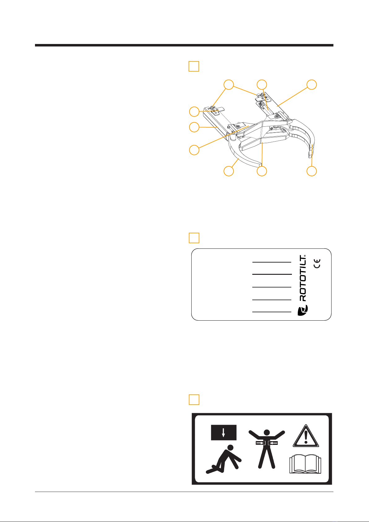
There is information in the Description chapter about
how Rototilt®is built and functions.
Under Handling information, Maintenance,
Troubleshooting and Diagrams there are
step-by-step instructions for the use and
maintenance of Rototilt®.
To ensure the best possible performance, economy
and long service life, follow all instructions in this
manual correctly.
This will also prevent the most common causes of
accidents that occur during use or maintenance.
CE marking
Rototilt®is CE marked, which means it is designed,
produced and described in accordance with EC
Directives.
If Rototilt® is modied, supplemented with other
products or used in applications for which the
product is not approved, this marking will cease
to be valid.
Warranty and warranty claims
Contact your dealer.
Other information
Spare parts lists and repair instructions are available
from your Rototilt®dealer.
This information is correct at the time of going to
print. All possible measures have been taken to
ensure that the content is as complete and accurate
as possible. In spite of this, no responsibility can be
taken for missing or incorrect information.
The manufacturer reserves the right to implement
improvements at any time without altering the basic
function of the model, with the aim of further Rototilt®
development
This may occur without necessarily updating these
instructions for use. Contact the nearest dealer in
order to obtain information about possible changes.
No part of this publication may be reproduced,
translated, stored or communicated electronically,
mechanically, photographically or in any other way
without prior written consent from Rototilt Group AB.
This provision covers the contents in whole or in
part, regardless of whether the contents are used in
other publications or not.
Introduction

2200004 _7225 2018 04 20 English
EN
Unfortunately, the majority of workplace accidents
occur due to thoughtlessness or carelessness.
These can be avoided by taking preventative
safety measures. No safety equipment or devices,
no matter how well constructed, is better than
machine operator care and observation.
Read through the instructions for use carefully and
make sure you understand the contents before using
Rototilt®. Poorly performed or incorrect handling and/
or assembly may result in serious or life-threatening
injury.
Observe the safety instructions contained in this
publication in order to protect Rototilt®and to prevent
personal injury.
Read and note all warning decals on Rototilt®.
The warning decals have a yellow background
with black text.
Do not permit untrained individuals to handle, repair
or perform maintenance on Rototilt®.
Otherwise refer to the base machine safety
instructions.
Description of warning texts
Warning texts are classied in three levels as shown
below, according to how serious the consequences
of an accident can be.
DANGER!
Indicates an accident risk if the instruction
is not followed. Accidents will lead to
serious personal injury, death and/or
serious damage to property.
Warning!
Indicates an accident risk if the instruction
is not followed. Accidents may lead to
serious personal injury, death and/or
serious damage to property.
IMPORTANT!
Indicates an accident risk if the instruction
is not followed. Accidents may lead to
personal injury and/or damage to property.
Safety instructions

2200004 _7225 2018 04 20 English
EN
Grapple module
IMPORTANT!
The grapple module is only intended for
installation on Rototilt®units from Rototilt
Group AB.
Before use
• Before use, check that no-one is within the base
machine’s risk area. Increase the risk area when
handling long objects with the grapple.
• Check that the tool used in combination with
Rototilt®does not interfere with the grapple
module. In certain cases, it may be necessary
to adjust the tool.
IMPORTANT!
Read through the Handling chapter.
IMPORTANT!
Information on the grapple module
operating controls can be found in the
control system’s instructions for use.
IMPORTANT!
Read through the instructions for use
carefully and make sure you understand
the contents before using the grapple
module.

2200004 _7225 2018 04 20
A
DD
E
B
C
English
EN
Check that the grapple module does not interfere
with buckets or other tools intended for use beneath
the Rototilt®. Specic requirements for attachment
systems are shown below.
IMPORTANT!
Make sure any external supports do not
collide with the grapple module.
See gure on right.
Quick coupler
Quick coupler B27
Quick coupler LE
Max 77
Max 175
Max 99
A B C D
(max)
E
(max)
S40 242 40 300 100 40
S45 292 45 430 125 45
S50 272 50 430 125 45
S60 342 60 480 150 60
S70 452 70 600 250 75
S80 592 80 670 250 90

2200004 _7225 2018 04 20 English
EN
During use
• Never stand or pass beneath a raised object.
• Risk of falling objects.
• Crush risk.
• An installed Rototilt®and grapple module
changes base machine geometry. Risk of
collision between the tool and the base machine.
• An installed Rototilt®will alter base machine
weight parameters. The values specied in the
base machine lifting table must be reduced by
the weight of the Rototilt®.
• Exercise caution when handling long objects
with regard to the forces of inertia and the
extended risk area.
• The grapple arms may not be used for anything
other than gripping objects suitable for lifting.
MAY NOT BE USED FOR LIFTING PEOPLE.
• Never attach chains or straps around the
grapple arms for lifting.
Use the base machine lifting hook instead.
• It is not permitted to lift weights greater than
the lifting capacity stated in the machine
specications when using the Rototilt®and
grapple module.
See base machine instructions for use.
• Never exceed the maximum lifting capacity.
See information plate.
• Always bear in mind the risk of dropping the load
when lifting objects with the grapple arms.
• When the grapple is not in use, keep the grapple
arms retracted.
IMPORTANT!
Due to the parallel hydraulic connection,
the grapple arms may move at dierent
rates.
The grapple arm with the lowest load will
move rst.
TECHNICAL SPECIFICATION
Model G400B G600B RG600 RG800 RG850 RG900 RG1050
Suitable Rototilt®model RT10
RT20B
RT20B
RT30
R3
R4
R4
R6
R6 R6
R8
R8
Weight (kg) 36 68 68 105 105 166 185
Max hydraulic pressure (mPa) 25 25 25 25 25 25 25
Gripping force, max open (kN) 4.4 5.6 5.6 7.7 8.3 11.7 11.7
Gripping force, tip-tip (kN) 7.1 8.9 8.9 13.6 14.1 19.8 21.2
Max lifting capacity (kg) 300 500 500 1 000 1 000 1 300 1 300
Grapple open, min (mm) 400 600 600 800 850 900 1 050

2200004 _7225 2018 04 20 English
EN
After use
• Always park the Rototilt®with an installed tool
with the tool resting on the ground. Never park
with the Rototilt®hanging in the air. See base
machine regulations for parking.
• Follow the instructions in the Maintenance
chapter.
Accidents or breakdowns
In the case of accidents or breakdowns, do as
follows:
• Disconnect the grapple unit according to the
Removing the grapple module chapter.
• Be aware of the environment; make sure no
hydraulic oil leaks out.
• Contact your dealer or authorized service
provider.
During maintenance
Warning!
During service, maintenance or other
work on the grapple module, disconnect
electrical connections and all hydraulic
hoses connected to the base machine.
Risk of personal injury, exercise caution!
Warning!
During service, maintenance or other
work on the Rototilt®, disconnect electrical
connections and all hydraulic hoses
connected to the base machine Risk of
personal injury, exercise caution!
WARNING!
Do not manually assist hydraulic valves.
Risk of personal injury.
Only use Rototilt®spare parts. Rototilt Group AB will
accept no liability for the product if other spare parts
are used.

2200004 _7225 2018 04 20
3
4
5
1
2
English
EN
Description
General
The grapple module is a hydraulically driven tool
intended for installation and use on Rototilt®units
from Rototilt Group AB.
Tools connected below a Rototilt®unit and the
grapple module are assumed to be of a type
normally used for work with the base machine.
The grapple module is installed on the quick coupler
and does not aect the unit’s total installation height.
The grapple module is a Rototilt®accessory
intended for use for light grappling and handling
work.
The grapple module is used as a supplement to
other tools, but does not replace a grapple tool
connected beneath the tiltrotator.
Warning!
Never exceed the maximum lifting
capacity.
See information plate.
Other types of use may not take place without the
manufacturer’s approval.
The grapple arms are connected in parallel
hydraulically to the extra function performed by the
swivel. Operation is controlled using the appropriate
levers.
The G-AG/RG series grapple cylinders are tted with
pilot controlled non-return valves or load holding
valves to maintain hydraulic pressure during gripping
operations.
IMPORTANT!
Valve functions form an important part of
the safety system.
Overview
1. Base machine.
2. Base machine quick coupler (not present with
direct connection).
3. Rototilt®.
4. Grapple module.
5. Tools.

2200004 _7225 2018 04 20
Weight
Lifting Capacity
Serial No
Manuf. Year
S-922 21 Vindeln
SWEDEN
Type
12 3
4 56
7
8
9
A
B
C
English
EN
Grapple module
See g. A
The grapple module comprises:
1. Chassis.
2. Grapple arm, single.
3. Grapple arm, double.
4. Grapple cylinders.
5. Cylinder protection.
6. Outlet, extra function*.
7. Pin.
Information plate.
See Fig. B; for location, see Fig. A, position 9
Type
Serial No.
Manuf. Year.
Weight.
Max Pressure.
Lifting Capacity.
CE marking
Warning decal
See Fig. C; for location, see Fig. A, position 8
Warning decal, grapple module.
* Applies to certain models

2200004 _7225 2018 04 20 English
EN
Grapple module operation
The grapple module’s two hydraulic cylinders are
connected in parallel hydraulically and are operated
via the extra outlet on the Rototilt®quick coupler.
Oil ow in one direction opens the grapple arms,
while oil ow in the other direction closes them.
Note which control levers operate the functions
“open grapple alarms” and “close grapple arms”
respectively.
Information concerning the control levers that
operate the grapple module can be found in the
base machine control system manual.
Extra function operation may dier from unit to unit
depending on the control system the Rototilt®is
equipped with.
Extra function
(*does not apply to G400B and RG series)
It is possible to connect an extra function on grapple
modules G600B, G800B, G850B, G910 and G1060.
To use the extra function, turn the nuts for the
directional valves (located in the rear part of the
cylinders) in direction E. See Fig. 1.
IMPORTANT!
The directional valves on both cylinders
must be redirected.
Turning the nuts on the directional valves switches
between operation of the grapple function and any
other hydraulically driven tool connected to the extra
function outlet. Use a wrench to turn the nuts.
To use the extra function, remove the plug and
connect the connection. See Figure 2.
For other information regarding the extra function
and other Rototilt®functions, see the Instructions
for use for Rototilt®.
Handling
Figure 1
Plug
Figure 2
Model Plug, dimension
G400B -
G600B G1/2"
G800B G3/4"
G850B G3/4"
G910 G3/4"
G1060 G3/4"
Grapple
Extra
Grapple
Extra

2200004 _7225 2018 04 20 English
EN
Extra function G400B
An extra function can be connected on model
G400B, if a valve block with the ability to close
the “grapple open channel” is installed.
To connect a hydraulic tool to the extra function,
do as follows:
1. First retract the grapple arms to their closed
position.
2. Then turn the bolt on the directional valve
clockwise to close the grapple open function.
See Figure.
3. Remove the plugs from the outlets and connect
the hydraulically driven tool.
WARNING!
The extra function is always pressurized.
Even if the grapple module is used, the
extra function is pressurized in both
directions.
Closes the “grapple
open” function
Opens the “grapple
open” function
Outlet, extra function
Extra function RG- series
There is an extra function outlet in the quick coupler
on the RG series.
See the Quick Coupler section in the tiltrotator
instructions for use.

2200004 _7225 2018 04 20 English
EN
Removal/installation
Tools to have available:
• Hexagonal socket wrench.
• Torque wrench.
• Combination wrenches.
• Plastic mallet.
• Collection vessel.
Bolts
Tension pin
Rear shank lock
IMPORTANT!
Be aware of the environment; make sure
no hydraulic oil leaks out.
Exercise caution when replacing hydraulic
components; use a collection vessel.
2
5
7
Grapple module removal
1. Rest the Rototilt® at against the ground.
Run the grapple arms out to the open position
and then switch o the base machine.
Disconnect the hydraulic hoses between
the base machine and the Rototilt®.
2. Removes the four attachment bolts from
the grapple frame. Allow the bolts to remain.
3. Remove the hydraulic hoses between the
grapple module and the quick coupler.
4. Remove the four bolts fully, carefully tap the
back of the cylinder protection while pulling
the grapple module and a quick coupler apart.
5. On some models it is necessary to remove
the rear shank locks before it is possible to
pull them apart.
On the AG/RG series, it is necessary to remove
the rear stay before the grapple module is
removed from the quick coupler.
6. Install the plate, adapter and cover for the
hydraulic hoses and plunder the connections.
7. If the tension pins are still in the quick coupler,
remove them with the aid of pliers.
Then fasten the protection plates. Ideally,
stow the tension pins in the grapple module
attachment holes (to be ready for grapple
module reinstallation).

2200004 _7225 2018 04 20 English
EN
Grapple module installation
Perform installation in reverse order.
See tightening torque table.
Connection
In order for the grapple module to function correctly,
attachment must take place as illustrated.
See Figure below.
Model Tightening torque
G400B 130 Nm
G600B,RG600 330 Nm
G800B, RG800 330 Nm
G850B, RG850 330 Nm
G910, RG900 600 Nm
G1060, RG1050 600 Nm
Danger!
In the case of incorrect connection,
gripping force may be lost and the load
dropped.
Dropping a load may result in damage to
property and the risk of personal injury or
serious personal injury.

2200004 _7225 2018 04 20 English
EN
Figure 1.
Figure 2
Adapting pins
The pins on grapple modules G910/G1060 are
adapted to t dierent tools in the following manner:
1. Undo the nuts that secure the pins to the
grapple module.
2. Move the pins and t the nuts.
For other information regarding extra functions and
other Rototilt®functions, see the Instructions for use
for Rototilt®.
Adaptation*
*(G910 and G1060 models)
There are two pin variants for the G910/G1060
grapple modules.
These pins can be adapted to t dierent types
of quick coupler.
In position 1, the grapple module will t e.g.
the following quick couplers. See Fig. 1.
• B27/RT80 (G910)
• S70 / RT60 (G910)
• OQ80/RT80 (G1060)
• S80/RT 80(G1060)
• CW30/RT60 (G1060)
• CW30/RT80 (G1060)
In position 2, the grapple module will t e.g. the
following quick couplers. See Figure 2.
• S70/RT80
• S2/RT80
• S1/RT80

2200004 _7225 2018 04 20 English
EN
General
Read through the safety instructions prior to any
maintenance.
The section deals with preventive maintenance and
service work on the grapple module.
IMPORTANT!
More extensive adjustments and repairs
must be carried out by an authorized
service workshop. Contact your supplier
for information on service providers.
Spare parts
Order spare parts through your dealer.
Always provide the grapple module a model and
manufacturing number as noted on the information
plate.
Only use original spare parts from Rototilt Group
AB. Rototilt Group AB will accept no liability for the
product if other spare parts are used.
Daily Checks
• Check for visible defects.
• Check for oil leaks.
• Check that all decals are legible.
• Function control for all functions.
• Check for chang on hydraulic hoses.
IMPORTANT!
Carry out maintenance actions.
Lubricate every 8 operating hours.
Lubricate the grapple arm bearings and hydraulic
cylinders every 8 operating hours.
Maintenance
Lubrication points G400B
Lubrication points on all grapple
modules except G400B
IMPORTANT!
Be aware of the environment; make sure
no hydraulic oil leaks out.
Exercise caution when replacing hydraulic
components; use a collection vessel.

2200004 _7225 2018 04 20
C
C
C
C
O
CC
O
O
O
O O
(Close) (Open)
(Close) (Open)
English
EN
Diagrams
Hydraulics diagram G400B
with hydraulic manifold for closing the grapple open channel.
Left Right
ExtraExtra

2200004 _7225 2018 04 20
(Close) (Open)
English
EN
Hydraulics diagram G600B, G800B, G850B, G910, G1060
Left Right
ExtraExtra

2200004 _7225 2018 04 20
A B
PT
English
EN
Hydraulics diagram
RG600

2200004 _7225 2018 04 20
A B
PT
English
EN
Hydraulics diagram
RG800, RG850, RG900, RG1050
This manual suits for next models
5
Table of contents
Other ROTOTILT Construction Equipment manuals