Roughneck 25621 User manual

ULTRA LOW PROFILE LIFT
TABLE CART
OWNER’S MANUAL
WARNING: Read carefully and understand all INSTRUCTIONS
before operating. Failure to follow the safety rules and other basic
safety precautions may result in serious personal injury.
Item# 25621

Page 2 of 9
Thank you very much for choosing a Roughneck™ Product! For future reference, please complete the
owner’s record below:
Model: _______________ Purchase Date: _______________
Save the receipt, warranty and these instructions. It is important that you read the entire manual to
become familiar with this product before you begin using it.
This machine is designed for certain applications only. The distributor cannot be responsible for issues
arising from modification. We strongly recommend this machine is not modified and/or used for any
application other than that for which it was designed. If you have any questions relative to a particular
application, DO NOT use the machine until you have first contacted distributor to determine if it can or
should be performed on the product.
For technical questions, please call 1-800-222-5381.
INTRODUCTION
ULTRA LOW PROFILE LIFT TABLE CART is a vehicle for short-range loading and unloading. Because
there will be no sparks and electromagnetic fields during operation, this cart is especially suitable for
automobile loading and unloading in your workshop and warehouse, dock, station, market, etc. This
product has smooth lift, flexible rotation that makes operation convenient. Two swivel casters are
equipped with brakes, safe and reliable. This cart is an ideal tool to reduce labor intensity, improve the
production efficiency and achieve safety loading and unloading.
TECHNICAL SPECIFICATIONS
Model
25621
Rated Capacity (Q)
1000lbs.
Max. Fork Height (H)
40in. (1016mm)
Min. Fork Height (h)
1.2in. (30mm)
Load Center (C)
≤15.75in. (400mm)
Fork Length (L)
36in. (915mm)
Fork Side Width (E)
24in. (610mm)
Overall Length (A)
52in. (1322mm)
Overall Width (B)
31.5in. (800mm)
Overall Height (H1)
55.7in. (1415mm)
Min. Turning Radius (R)
56.5in. (1435mm)
Front Wheel Wheelbase (X)
6in. (154mm)
Rear Wheel Wheelbase (Y)
44in. (1102mm)
Front Wheel Size
3.14x1.18in.(Φ80x30mm)
Rear Wheel Size
5in. (Φ125mm)
Environmental Temperature
-25℃~+45℃(-13℉~+113℉)
Net Weight
250lbs. (113kgs)

Page 3 of 9
GENERAL SAFETY REGULATIONS
WARNING: Read and understand all instructions. Failure to follow all instructions listed below
may result in serious bodily injury or death, and/or property damage.
WARNING: The warnings, cautions, and instructions discussed in this instruction manual
cannot cover all possible conditions or situations that could occur. It must be understood by the
operator that common sense and caution are factors that cannot be built into this product, but must be
supplied by the operator.
•Keep the work area clean and dry. Damp or wet work areas can result in injury.
•Keep children away from work area. Do not allow children to handle this product.
•Always wear ANSI-approved safety glasses and heavy-duty work gloves during
assembly and use. Do not wear loose clothing or jewelry, which can get caught in moving
parts.
•Store idle equipment. When not in use, tools and equipment should be stored in a dry location
to inhibit rust.Always lock up tools and equipment, and keep out of reach of children.
•Use the right tool for the job. Do not attempt to force small equipment to do the work of larger
industrial equipment. There are certain applications for which this equipment was designed. It
will do the job better and more safely at the capacity for which it was intended. Do not modify
this equipment, and do not use this equipment for a purpose for which it was not intended.
•Check for damaged parts. Before using this product, carefully check that it will operate
properly and perform its intended function. Check for damaged parts and any other conditions
that may affect the operation of this product. Replace damaged or worn parts immediately.
•Do not overreach. Keep proper footing and balance at all times to prevent tripping, falling,
back injury, etc.
•DO NOT use the equipment when tired or under the influence of drugs, alcohol, or
medication. Amoment of inattention while operating this equipment may result in serious
personal injury.
•Industrial applications must follow OSHA requirements.
SPECIFIC OPERATION WARNINGS
WARNING: NEVER OVERLOAD!! Make sure the operator be familiar with the cart controls
before being authorized to operate it.
WARNING: DO NOT LIFT PERSONNEL. DO NOT LIFT LOADS OVER PEOPLE.
WARNING: DO NOT walk under a suspended load. DO NOT perform any work on a
suspended load that requires a worker to be positioned under the suspended load.
•Do not use damaged cart or cart that is not working properly.
•Use only on a hard, level surface.

Page 4 of 9
•Do not exceed the rated capacity 1000lbs.
•Before moving the load, assure that the load is centered and a load-restraining device is
recommended to secure the load. DO NOT move unstable loads.
•Do not use on sloping ground.
•Do not move the cart when loading in a raised position of height above 11.8in.
•Do not randomly regulate the safety valve.
•Do not allow people to sit or ride on the cart.
•Do not transport the loads during the lifting process.
•All maintenance is to be performed by professional personnel strictly in accordance to the
related information in this manual.
•Make sure all persons stay clear of the supported load.
•Keep feet and hands away from under the lowering table. Safety shoes should be worn during
operation.
•Make sure that all nuts, bolts and split pins are sufficiently fastened.
OPERATION INSTRUCTIONS
WARNING: Before use, check any broken or loose parts.
(1) Before operating, be sure the load is centered and stable on the platform.
(2) To lift the load on the cart, continue stepping on the foot pedal as the platform rises to the required
height.
(3) To lower the load on the cart, turn the Star Handle slowly and gently until the platform is lowered to
the desired height.
WARNING:
People will be seriously hurt or the cart will be damaged if turning the Star Handle quickly when
lowering the load.
Never shut off the oil return valve sharply, or the cart and/ or loads can be damaged.
Leaving the cart: Whenever the operator leaves the cart, the platform must be fully lowered.
Visibility: The operator must always have a clear view of the path in the direction of travel.
Load handling: Only stable and safely arranged loads within the rated capacity of the cart should be
handled. Operators are not to pick up and move loads that are too heavy. If, upon attempting to lift the
load, the rear wheels of the cart begin to rise, set the load down immediately and obtain proper
equipment to lift a load of that size.
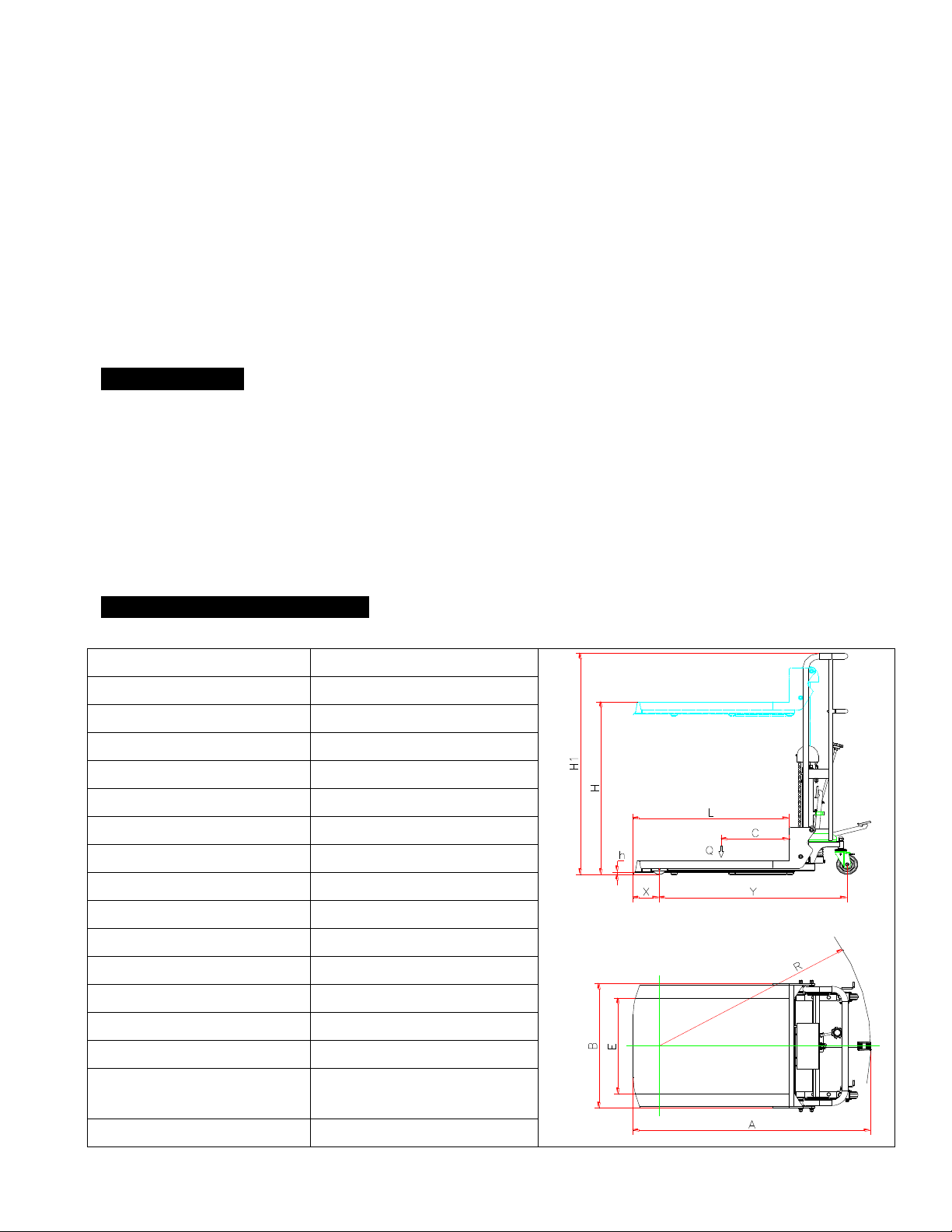
When picking up a load, center the load evenly on the platform, (The load center position is showed in
TECHNICALSPECIFICATION section), and engage loads securely and stably.
Loads can be of many sizes and descriptions, such as boxes, bags, packages, or other small objects.
All loads should be made stable by either interlocking the objects, or strapping or shrink-wrapping the
load, to prevent individual objects from falling off the cart.
Long loads reduce the stability of a cart. Long, wide, or high loads require more room, so watch the
clearance. The load may be very secure until something is run into that shifts the cart’s center of gravity.
This creates the potential for a lateral overturn. Lifting long loads that extend directly in front changes
the weight center of the cart and reduces the lifting capacity of the cart. When right angle stacking or
moving with a low raised load to clear low objects, move very slowly and avoid sharp turns.
WARNING:
The length of cargos handled must be less than 35”, while width less than 36”.
Do not move with loads raised higher than 11.8”, and move with a low raised load just for short
distance.
Move very slowly and avoid any turns when moving with a raised load.

Page 5 of 9
Operating surfaces: Operate the cart only on level surfaces. Make sure the surface will support the
weight of the vehicle and loads and not create unstable conditions before entering the area.
WARNING: Do not use on grades, ramps, slopes, and inclines.
Pedestrians: The operator of the cart is responsible for operating in a safe manner; this includes
avoiding all pedestrians in the work area.Always face the direction of travel.
Watch for people in the work area because they may not watch for the cart. If it is determined that they
may not see the lift cart, do not move until eye contact is made. If the view is blocked because of the
load, travel backwards. If the lift cart must move forward, make sure that people are out of the way and
move the cart slowly.
Watch for employees working in the same area. Do not let anyone walk under raised forks or load. If
someone is required to hold or position the load while the lift cart is moving –STOP. There is something
wrong. If unable to handle the load alone, change the load or the equipment. Otherwise, someone will
eventually be hurt badly. Do not take this risk. Find a better way to move the load.
Cart tipover: Lift trucks can be tipped over if not operated properly. Observe the following procedures
to lessen the possibility of a tipover.
Slow down before turning. Go into and out of turns slowly, using a slow rotation of the steering
wheel.
Drive with the platform lowered and the load stabilized. Raising a load high moves the center of
gravity and lowers the capacity.
Check capacities –do not overload the cart.
Do not move unstable loads.
Check your overhead clearance. Keep the cart at least 10 feet from any overhead electrical wires.
Watch for overhead obstructions like pipes and low doors. If they are hit while moving, the cart can
tip over.
Turning with the loaded platform raised can tip over the cart even at slow speeds.
Take the time necessary, slow down, and operate safely.
MAINTENANCE
Only use clean hydraulic oil, always keep enough hydraulic oil in the system.
Replace hydraulic oil on a yearly basis.
The air may come into the hydraulic oil because of transportation or pump in upset position. It can
cause that the platform do not elevate while pumping. The air can be banished by stepping on the
foot pedal up and down for several times.
Daily check of the pallet truck can limit wear as much as possible, special attention should be paid
to the wheels, the axles, as thread, rags, etc. It may block the wheels. The cart should be unloaded
and lowered in the lowest position when the job is over.
Use motor oil or grease to lubricate all movable parts.

Page 6 of 9
TROUBLESHOOTING
PROBLEM
POSSIBLE CAUSE
CORRECTIVE ACTION
The platform can not be
up to the max. height.
The hydraulic oil is not enough.
Unscrew bolt on oil cylinder and
pour in enough clean hydraulic oil.
The platform can not be
lifted up.
The oil viscosity is too high or
there is no enough oil.
Fill in suitable hydraulic oil.
The oil has impurities.
Change the oil.
Oil drain valve, oil drain screw
or torsion spring doesn't work.
Inspect the tightness of torsion,
adjust/ re-stall check valve if
needed.
Oil drain valve and/ or oil drain
screw are not in position.
Loosen torsion spring and screw,
adjust the positions.
The platform can not be
descended.
Oil drain screw is not adjusted
properly.
Adjust the oil drain screw.
The piston is deformed.
Replace the piston.
Mast rollers and chain wheels
are stuck.
Replace the bearings.
Leaks
Sealing parts worn or damaged.
Replace with the new one.
Some part cracked or worn into
small.
Replace with the new one.
Bolted joints are loose
Tighten places where are loose.

Page 7 of 9
DIAGRAM & PARTS LIST

Page 8 of 9
NO.
Description
Quantity
NO.
Description
Quantity
1
Frame
1
47
Combination Washer D10
1
2
Front Wheel D80x30
2
48
Screw M10x1
1
3
Bearing 6201
4
49
Pump Piston
1
4
Nylon Washer
4
50
Spring Cover
1
5
Front Wheel Shaft
2
51
Spring
1
6
C-Clip D12
4
52
DHS Ring 14x22x4.5/6
1
7
Bolt M10x20
2
53
UHS Ring 14x22x6
1
8
Cover Form Nut M16
2
54
Pump Cylinder
1
9
Spring Washer D16
2
55
Copper Washer D28x3
1
10
5' Swivel Wheel Holder
2
56
Valve
1
11
Lifting Frame
1
57
Plate Spring
1
12
Screws M6x40
2
58
Spring Washer D6
1
13
Screw M12x110
2
59
Screw M6x14
1
14
Nut M12
4
60
Ball D8
2
15
Split Cotters
2
61
Pole
1
16
U-shape Bolt D60-M8
1
62
Spring
2
17
Washer D8
2
63
Copper Washer D10
2
18
Nut M8
4
64
Hexagonal Flange Bolts
2
19
Bolt M8x25
1
65
Elastic Pin D4x35
1
20
Bolt M12x20
4
66
Star Handle
1
21
Washer D12
8
67
Bolt M12
1
22
Nut M12
4
68
Cardan Joint
1
23
Screws M6x14
2
69
Screw M5x8
1
24
Spring Washer D6
2
70
Spring Seat
1
25
Washer
2
71
Screw M5x8
1
26
Cover Shell
1
72
Spring
1
27
Screws M10x45
1
73
Screw M5x8
2
28
Sprocket Wheel Shaft
1
74
Washer D5
2
29
Sprocket Wheel
2
75
Put Oil Screw
1
30
Bearing 6205
2
76
O-ring D11x1.9
1
31
C-Clip D52
2
77
Hexagonal Valve Set
1
32
C-Clip D25
2
78
Copper Washer D16
1
33
Chain
2
79
Ball D6.7
1
34
Chain Fork Quarter
2
80
Rubber Plate
1
35
Chain Quarter
2
81
Foot Pole
1
36
Semi-closed Card Spring
2
82
C-Clip D12
4
37
DHS Ring 30x38x4.5/6
1
83
Pressure Wheel
1
38
O-ring D35x3.1
1
84
Bushing
2
39
Cylinder Cover
1
85
Pressure Wheel Shaft
2
40
O-ring D58x3.1
1
86
Shelves
1
41
UHS Ring 40x30x6
1
87
Bushing
4
42
O-ring D43x3.1
1
88
Roller
4
43
Copper Washer D38x3
1
89
Semicircle Pin
8
44
Piston Rod
1
90
Block Circle
4
45
Inner Oil Cylinder
1
91
C-Clip D20
4
46
Outer Oil Cylinder
1
For replacement parts and technical questions, please call 1-800-222-5381.

Page 9 of 9
WARRANTY
One-Year Limited Warranty
Distributed by
Northern Tool + Equipment Co., Inc.
Burnsville, MN 55306
NorthernTool.com
Made in China
Table of contents
Popular Outdoor Cart manuals by other brands

HAUL MASTER
HAUL MASTER 60533 Owner's manual & safety instructions

Royal Catering
Royal Catering RCSW-3R user manual

Moretti
Moretti SKEMA FORM EOLO instruction manual

Dyck-Carts
Dyck-Carts SAM manual

Noble House Home Furnishings
Noble House Home Furnishings BARCRAFT CHO796 Assembly instructions

Royal Catering
Royal Catering RCTW 7 TB user manual