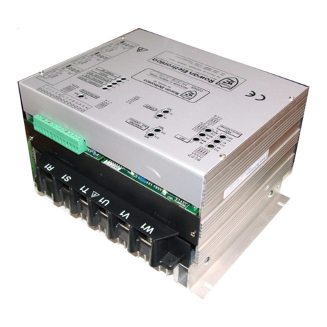
Rowan Elettronica 470 Series User manual

Rev.11
dated
10/01/17
Instruction Manual code MANU.470S
MULMUL
MULMUL
MUL
TIFUNCTION THREE PHASE DRIVESTIFUNCTION THREE PHASE DRIVES
TIFUNCTION THREE PHASE DRIVES
470 SERIES470 SERIES
470 SERIES
SOFSOF
SOFSOF
SOFTT
TT
T-ST-ST
-ST-ST
-STARTERARTER
ARTERARTER
ARTER
STST
STST
STAA
AA
ATIC SWITCHTIC SWITCH
TIC SWITCHTIC SWITCH
TIC SWITCH
POWER/ENERGY REGULPOWER/ENERGY REGUL
POWER/ENERGY REGULAA
AA
ATORTOR
TORTOR
TOR
VV
VV
VOLOL
OLOL
OL
TT
TT
TAGE REGULAGE REGUL
AGE REGULAGE REGUL
AGE REGULAA
AA
ATORTOR
TORTOR
TOR
Via U. Foscolo, 20 - CALDOGNO - VICENZA - ITALIA
Tel.: 0444 - 905566 (4 linee r.a.)
Fax: 0444 - 905593 E-mail:[email protected]
InternetAddress: www.rowan.it
iscritta al R.E.A di Vicenza al n. 146091
C.F./P.IVA e Reg. Imprese IT 00673770244
The Italian answer to all automation needs

PAGE
2 / 64
Via Ugo Foscolo, 20
36030 - CALDOGNO - VICENZA - ITALY
Instruction Manual code MANU.470S Rev.11 - 10/01/17
GENERAL RECOMMENDATIONS
BEFORE INSTALLATION
Three-phase 470 series drive have been created with 4 programmable features (see Chapt. 2 DRIVE FUNCTION
SELECTION):
- SOFT-STARTER: to start/slow down three-hase asynchronous motors.
- STATIC SWITCH: to statically command three-phase loads in alternative to electro-mechanical contactors, by ZERO
CROSSING antijamming managing.
- POWER/ENERGY REGULATOR: to control the temperature in ovens with electric resistances by wave- train regulation
in ZERO CROSSING.
- VOLTAGE REGULATOR to control voltage/current on Rowan High slip motors and in general on feeders voltage/current
adjustable; the voltage is adjusted by the PHASE PARTIALIZATION technique.
For this reason, this manual is divided into the following parts:
- Chapt. 1-2-3-4 gives instructions common to all functions.
-Chapt. 5-6-7-8-9 describe SOFT-STARTER function (see Chapt. 1 and 5 for a quick start-up of the function).
- Chapt. 10 describes technical characteristics common to the following functions:
STATIC SWITCH, POWER/ENERGY REGULATOR, VOLTAGE REGULATOR.
Chapt. 11 describes the STATIC SWITCH function.
Chapt. 12 describes the POWER/ENERGY REGULATOR.
Chapt. 13 describes the VOLTAGE REGULATOR.
ATTENTION! Before starting, select the function needed by reading chapt. 2 -
"DRIVE FUNCTION SELECTION"
ROWANELETTRONICA s.r.l. declines allresponsibilityforany imprecisions inthismanualdue toprintingand/orcopy errors.
Moreover it can make changes any variations it may deem necessary to improve the products under its sole discretion and
without notice.
The data and characteristics provided in this manual have a maximum tolerance of ±10%, unless otherwise indicated. The
diagrams are mere guidelines and should be adapted to the specific needs of the user.
Before installing , wiring or any other operation on the actuator, carefully read this manual to ensure that the correct
operations are made and all related safety measures are taken.
It is strictly forbidden to use the 470 actuators in any way other than for the operations indicated in this manual.
This instruction manual addresses qualified technicians who know the standards to respect in the installation and
operation of the actuator, in compliance with safety regulations and the protection of this type of equipment.
The actuator and its load can create hazardous situations for the safety of objects and individuals, the user and installer
must comply with statutory regulations.
This actuar presents a a current lekeage to ground (<1mA), so DO NOT supply it without connecting the PE terminal to
ground first.
The drive doesn't have any SIL ability (Safety Integrity Level) as per standard IEC/EN61508, so drive contacts cannot be
considered a valid method for a safety stop; in certain programming or actuator fault conditions, its shut down may not
mean that the motor will stop immediately. Only an electromechanical cut-off of the actuator from the power supply,
made by following IEC/EN61508 standards, will safely cut-off any motor command.
In the same way, in case of SOFT-STARTER function,the shaft stopped detector cannot be considered valid to carry out
operations in total safety (SIL ability).
Installation of the actuator in risky zones, containing flammable substances or combustible vapour or dust, can cause fire
or explosion. The 470 actuators must be installed away from such zones.
In all events prevent water or other fluids from penetrating the interior of the appliance.
Do not carry out dielectric rigidity tests on parts of the drive.
The product warranty is provided ex works Rowan E.; Terms and conditions are specified on the Sales Conditions that can
be requested to the Commercial Dept. or downloaded from our web site: www.rowan.it
Description of the Manual
General safety instructions
Warranty
Compatibility of the manual with the firmware 470S version
IThis manual is updated to the firmware 4.01. The firmware version can be read through the DISPLAYS menu on the
keypad, see FIRMWARE VERSION variable.

Instruction Manual code MANU.470S Rev.11 - 10/01/17
PAGE
3 / 64
Via Ugo Foscolo, 20
36030 - CALDOGNO - VICENZA - ITALY
Chapt.1 : THE KEYPAD page 5
General overview of the keypad...................................................................................................................................... page 5
Button descriptions .......................................................................................................................................................... page 5
Parameter modification procedure.................................................................................................................................. page 5
Chapt.2 : DRIVE FUNCTION SELECTION......................................................................................................................... pag. 6
Description of 100. menu.............................................................................................................................................. page 6
Settings : Actuator function, enabling fault reset by input,
locked access to keypad parameters, type of SCR trip.
Chapt.3 : FAULTS .............................................................................................................................................................. pages 7-9
Blockage description and fault list .................................................................................................................................. page 7
Parameters descriptioon on FAULT HISTORY menu.................................................................................................... page 8
Other possible cases of malfunctioning and solutions................................................................................................... page 8
FAULT 1 "MOTOR OVERLOAD" and FAULT10 "DRIVE OVERLOAD" description .................................................... page 9
Chapt.4 : SERIAL COMMUNICATION................................................................................................................................ pages 10-11
Description of modbus RTU serial transmission ............................................................................................................ page 10
Description of the serial communication parameters..................................................................................................... page 10
Instructions for the serial connection and transmission monitoring .............................................................................. page 11
Chapt.5 : RAPID INSTALLATION - SOFT-STARTER FUNCTION page 12
Typical wiring diagram and rapid installation of the soft-start ....................................................................................... page 12
Chapt.6 : TECHNICAL CHARACTERISTICS - SOFT-START FUNCTION...................................................................... pages 13-14
Technical characteristics ................................................................................................................................................. page 13
Tables with electrical characteristics .............................................................................................................................. page 14
Fixing power terminals and minimum sections on connection cables .......................................................................... page 14
Chapt.7 : INSTALLATION - SOFT-STARTER FUNCTION ............................................................................................... pages 15-18
Notes on the choice of soft-start ..................................................................................................................................... page 15
Dimensions ...................................................................................................................................................................... page 15
Typical position of a soft-start in a switchbox ................................................................................................................. page 16
Instructions for the cabling system and electromagnetic compatibility ......................................................................... page 16
Description of power terminal block ................................................................................................................................ page 17
Description of command terminal block ......................................................................................................................... page 17-18
General wiring diagram ................................................................................................................................................... page 18
Chapt.8 : DISPLAYS AND PARAMETERS - SOFT-STARTER FUNCTION.................................................................... pages 19-27
Keypad menu map of SOFT-START functions .............................................................................................................. page 19
Full parameter list ............................................................................................................................................................ page 20
Display menu list.............................................................................................................................................................. page 21
Modbus input/output commands ..................................................................................................................................... page 21
Modbus input/output status read..................................................................................................................................... page 21
Description of DISPLAYS menu................................................................................................................................... page 22-23
All displays monitoring soft-start operation
Description of 1. BASIC DATA menu .......................................................................................................................... page 23-24
Settings: basic parameters for rapid start-up
Description of 2. CONNECTION menu ........................................................................................................................ page 24
Settings : motor connection type.
Description of 3. SAFE MOTOR menu ........................................................................................................................ page 24
Settings : motor safeties: overload, underload, PTC sensor enabling.
Description of 4. REG. Imax SET menu ...................................................................................................................... page 25
Settings : internal or external regulation of start current.
Description of 5. 2nd SPEED SET menu .................................................................................................................... page 25
Settings : speed 2 of dual polarity motors.
Description of 6. STOP TYPE menu ............................................................................................................................ page 26
Settings : motor stop mode, in deceleration or counter current braking
Description of 7. START TYPE menu .......................................................................................................................... page 26
Settings : Release impulse at start
Description of 8. ENERGY SAVING menu .................................................................................................................. page 27
Settings : energy saving function
Description of 9. FUNCTIONS menu ........................................................................................................................... page 27
Settings : soft-start special functions
Chapt.9 : OPERATING MODES .................................................................................................................................... pages 28-33
Bypass of soft-start after start-up.................................................................................................................................... page 28
6-wire connection............................................................................................................................................................. page 29
Dual speed motor commands ......................................................................................................................................... page 30
External regulation of maximum start current ................................................................................................................ page 31
Kick Start .......................................................................................................................................................................... page 31
Motor stop modes ............................................................................................................................................................ page 32
Soft-starter for insertion line generator ........................................................................................................................... page 33
CONTENTS
Instructions for SOFTSTARTER function
Instructions for all functions

PAGE
4 / 64
Via Ugo Foscolo, 20
36030 - CALDOGNO - VICENZA - ITALY
Instruction Manual code MANU.470S Rev.11 - 10/01/17
CONTENTS
Chapt.10 : STATIC SWITCH, POWER/ENERGY REGULATOR, VOLTAGE REGULATOR............................................ pages 34-35
Common technical characteristics .................................................................................................................................. page 34
Tables with electrical characteristics .............................................................................................................................. page 35
Electro-magnetic compatibility ........................................................................................................................................ page 35
Chapt.11 : Function: STATIC SWITCH ............................................................................................................................ pages 36-40
Functioning description as STATIC SWITCH ................................................................................................................ page 36
Wiring diagram................................................................................................................................................................. page 36
Keypad menu map of STATIC SWITCH function .......................................................................................................... page 37
Full parameter list ............................................................................................................................................................ page 38
Display menu list.............................................................................................................................................................. page 38
Modbus input/output commands ..................................................................................................................................... page 39
Modbus input/output status reading................................................................................................................................ page 39
Description of menu DISPLAYS ..................................................................................................................................... page 39-40
Description of 1. menu BASIC DATA ............................................................................................................................. page 40
Chapt.12 : Function: POWER/ENERGY REGULATOR ................................................................................................... pages 41-45
Functioning description as POWER/ENERGY REGULATOR ....................................................................................... page 41
Wiring diagram................................................................................................................................................................. page 41
Terminal boards general description .............................................................................................................................. page 42
Keypad menu map of POWER/ENERGY REGULATOR ............................................................................................... page 43
Full parameter list ............................................................................................................................................................ page 43
Display menu list.............................................................................................................................................................. page 44
Modbus input/output commands ..................................................................................................................................... page 44
Modbus input/output status reading................................................................................................................................ page 44
Description of menu DISPLAYS ..................................................................................................................................... page 44-45
Description of 1. menu BASIC DATA ............................................................................................................................. page 45
Chapt.13 : Function: VOLTAGE REGULATOR ................................................................................................................ pages 46-59
Functioning description as VOLTAGE REGULATOR .................................................................................................... page 46
Wiring diagrams............................................................................................................................................................... page 46
Terminal boards general description .............................................................................................................................. page 47
Keypad menu map of VOLTAGE REGULATOR ............................................................................................................ page 48
Full parameter list ............................................................................................................................................................ pages 49-50
Modbus display menu list ................................................................................................................................................ page 50
Modbus input commands ................................................................................................................................................ page 50
Modbus output status reading ......................................................................................................................................... page 50
Description of DISPLAYS menu ..................................................................................................................................... pages 51-52
Parameters description from menu 1. BASIC DATA ..................................................................................................... page 53
Parameters description from menu 2. Iout LIMITS ........................................................................................................ page 54
Parameters description from menu 3. REGULATOR .................................................................................................... page 55
Parameters description from menu 4. CURRENT REGULAT....................................................................................... page 56
Parameters description from menu 5. SETUP OPERATOR ......................................................................................... page 57
Customizing keypad settings with OPERATOR parameters ......................................................................................... page 57
Standard settings and block diagrams about voltage regulator functions...................................................................... pages 58-59
Chapt.14 : ACTUATOR CODE CONSTRUCTION ............................................................................................................. page 60
Instructions for: STATIC SWITCH,
POWER/ENERGY REGULATOR, VOLTAGE REGULATOR functions

Instruction Manual code MANU.470S Rev.11 - 10/01/17
PAGE
5 / 64
Via Ugo Foscolo, 20
36030 - CALDOGNO - VICENZA - ITALY THE KEYPAD
Chapt.1
The keypad is used to modify the operating parameters (stored on an eeprom) and view parameters and measurements
during processing. The serial connection allows the keypad can be remote connected to the panel of a control switchbox, at a
maximum distance of 25 meters.
On request, Rowan Elettronica can supply the keypad remote connection lead.
General overview of the keypad
Button descriptions
The keypad comprises:
-A backlit alphanumerical display with 2x16 characters .
-Four pushbuttons with pressed feeling.
-Two LED's signalling drive (RUN) and fault block (FAULT).
ESCAPE returns to the start menu or a higher level and saves the settings.
PROGRAM, enters the submenus and the parameter change mode with sequential digit selection for number
settings.
UP, scrolls the variables FORWARD and increases the number setting selected by PROGRAM button.
DOWN, scrolls the variables BACKWARD and reduces the number setting selected by PROGRAM.
For example, SOFTSTART function, to modify the parameter 1.2 MOTOR In under the 1. BASIC DATA menu :
> Press P to view the 1. BASIC DATA menu
> Press P to view the first parameter in the 1.BASIC DATA menu, the 1.1 LINE FREQ parameter.
> Press UP to select par.1.2 MOTOR In.
> Press P to enter the modify parameter mode:
the display box with the rightmost digit of the setting will start blinking to indicate that it is now possible to modify it by the
UP and DOWN buttons.
> Press UP to increase and DOWN to decrease the setting.
> To modify the other digits just press P briefly, every time it is pressed the next digit to the left is selected, until it reaches
the leftmost and then returns to the rightmost and so forth.
> If the parameter can be both positive or negative, the sign is shown after the leftmost digit; to change it press P until it is
selected and then use UP to set + and DOWN to set -
> To memorise the new setting press ESCAPE (the selection will stop blinking).
> To return to the initial menu (DISPLAY STATUS) press ESCAPE again. To modify parameters with string selections use
exactly the same procedure, in this case UP and DOWN will select the strings available instead of numbers.
Parameter modification procedure
The keypad does not have its own memory to store the parameters
Caution!
E
P
RUN
FAULT
E
P
LINE FREQ.
1.1 50.0Hz
RUN: the LED lights up with
the actuator in drive and
operating
Display box for the description of the
selected menu/parameter/variable.
Display box for the number or string
setting of the parameter or variable.
Display box for the number of
the menu/parameter/variable .
Programming pushbuttons
FAULT : the LED lights up when the
actuator is blocked
See chapt.FAULTS for fault codes
and causes

PAGE
6 / 64
Via Ugo Foscolo, 20
36030 - CALDOGNO - VICENZA - ITALY
Instruction Manual code MANU.470S Rev.11 - 10/01/17
Chapt.2 FUNCTION SELECTION
The C470 series device can be applied in 4 ways (functions) that can be selected by parameter 100.1 APPLICATIONS.
They are:
- SOFT-STARTER: to starting/slowing down of three-phase asyncronous motors.
- STATIC SWITCH: to statically command three-phase loads in alternative to the use of electromechanical contactors, by
the ZERO CROSSING feature (against interferences).
- POWER/ENERGY REGULATOR: to control the ovens (electric resistance type) temperature by the wave -trains
regulation (by the ZERO CROSSING).
- VOLTAGE REGULATOR: to control voltage/current of high slip Rowan motors and feeder units in general that can be
regulated under voltage/current; the voltage is regulated by the PHASE-PARTIALIZATION technic.
The default function is SOFT-STARTER
PARAMETERS 100.
PRESS
ESCAPE
FOR 5 sec
DISPLAY STATUS
Description of the 100 menù parameters
WARNING! The 100. menu includes critical parameters affecting the regulator’s basic functions; always pay utmost
attention when setting them.
To access the 100. parameter programming screens, variables must be DISPLAYED. Pressing the ESCAPE button for 5
seconds gives access to the first parameter programming screen:
APPLICATIONS
100.1 SOFTSTART Par.100.1. It selects the function type
Setting range: SOFTSTART, 3AC_REG, 3AC_0CROSS, 3AC_ON/OFF
SOFTSTART = SOFTSTART function , starter/decelerator for three-phase asynchronous motors.
3AC_REG = VOLTAGE REGULATOR function , phase cutting voltage regulator.
3AC_0CROSS = POWER/ENERGY REGULATOR function, zero crossing wave train regulator.
3AC_ON/OFF = STATIC SWITCH function, zero crossing command.
PARAM BLOCK
100.3 NO Par.100.3. It allows to lock the access to keypad parameters
Setting range: NO, YES
If it is set to YES, with par.100.5 = DEFAULT, the system will prevent access to all parameters (except for menu 100).
If it is set to YES, with par.100.5 = OPERATOR, the system will prevent access to all parameters (except for menu 100 and
menu 1). BASIC DATA OPER.
SCR CONTROL TYPE
100.4 2. Par.100.4. It select the SCR control technique
This parameter is not enabled on STATIC SWITCH and POWER/ENERGY REGULATOR functions.
Setting field: from 1 to 3 for the SOFTSTARTER function, 1 for the VOLTAGE REGULATOR function
1 = OPEN LOOP control (suggested with "disturbed" supply line)
2 = OPEN LOOP control combined + FEEDBACKED control from voltage on SCR (must be used when starting a
loadless motor)
3 = for softstarter applied on network locking of a threephase generator (see chap.9 OPERATING MODES)
RESET FAULT EN
100.2 NO Par.100.2. It enables fault reset by a new run command
(forward/backward for SOFTSTARTER function)
Setting range: NO, YES.
MENU OPERATOR
100.5 DEFAULT Par.100.5. It configures the keypad parameter access methods
This parameter is enabled for the VOLTAGE REGULATOR function only.
Setting range: DEFAULT, OPERATOR
DEFAULT= Menu 1. BASIC DATA standard
OPERATOR = The 1.BASIC DATA menu is replaced by menu 1. BASIC DATA OPER., which can be customised with the
OPERATOR type setting parameters.
For a description of menu 1. BASIC DATA OPER. see the paragraph at the chapt.13:
“Customising keypad settings with OPERATOR parameters”.
LINEARIZATION
100.6 YES. Par.100.6. Linearization of the SCR control signal
This parameter is enabled for the VOLTAGE REGULATOR function only.
Setting range: NO, YES
NO = The control signal is directly proportional to the SCR fire angle.
YES = The control signal is linearized so that it is directly proportional to the RMS U1 V1 W output regulated voltage
(maximum accuracy with resistive load).

Instruction Manual code MANU.470S Rev.11 - 10/01/17
PAGE
7 / 64
Via Ugo Foscolo, 20
36030 - CALDOGNO - VICENZA - ITALY Chapt.3 FAULTS
The actuator faults are signalled by the FAULT LED lighting up in continuous on the keypad and the RUN LED turns off ; in this
casealloutputrelaysaredisactivatedandconsequently,intheSOFTSTARTfunction, theFORWARD,REVERSE,FAST(return
to SLOW) and BYPASS relay switches.
With the default settings, to know the cause of the block, just use the arrow buttons to select the monitor variable LAST FAULT.
This variable views the fault number associated with the cause of the block as described in the FAULT LIST table below.
There are two ways of resetting the blocked status of the actuator:
1) shut off and (after a pause) restore the logic power at terminals 39 and 41.
2) with the logic powered, disactivate and then activate the FORWARD or REVERSE drive command. To use this option set
par.100.2 RESET FAULT EN = YES.
Description of the actuator blocked status with faults list
TLUAF°N
TSILSTLUAF
1
DAOLREVOROTOM
ylnonoitcnufRETRATS-TFOSnodelbanetluaF pdna .SEY=01SSALCELBANE1.3.ra
.daolrevorotomgnolaretfatneserpsitI
2
DAOLREDNUROTOM
ylnonoitcnufRETRATS-TFOSnodelbanetluaF DAOLREDNU%2.3.rapnoteseulavehtnahtrewolsitnerrucrotomehtfipu-tratSfodneehttatneserpsitI .DAOLREDNUt3.3.rapnotesemitehtgnirud
3TIUCRICTROHSTUPTUO
.slanimrettuptuo1W1V1Unotiucric-trohS
4TIUCRICTROHSELUDOMRCS
ylnosnoitcnufROTALUGERYGRENE/REWOPdnaHCTIWSCITATSnodelbanetluaF .tiucric-trohsnisieludomRCSlanretnienotsaeltA
7ERUTAREPMETREVORCS
.gninepoeborpcimrehtybnoitnevretni;ecivedreloocseludomRCSnoerutarepmet-revO
01 DAOLREVOEVIRD
.spu-tratsesolcdnatneuqerfootrognolootybdesuacebnactluafsiht,noitcnufRETRATS-TFOSno;daolrevoevirD
11
ERUTAREPMETREVOCTPROTOM
snoitcnufROTALUGEREGATLOVdnaROTALUGERYGRENE/REWOP,HCTIWSCITATSnodelbanetluaF ylno SEY=ELBANECTPROTOM4.3.raphtiw sah)23-72slanimretevirdehtotdetcennocdna(rotomehtnidellatsnieborpCTPehtnehwtneserpsitI .erutarepmet-revonadetceted
21
DAOLREVOROTALUGER
ylnonoitcnufROTALUGEREGATLOVnodelbanetluaF .SEY=ELBANEDAOLREVO8.2.rapdna 01.2.rapnotesemitehtrofDAOLREVO9.2.rapnotestimilehtrevostegtnerrucehtnehwtneserpsitI .EMITDAOLREVO
31 ENILREWOPNOYLAMONA
.1T1S1RslanimretenilrewopehtfosesahpehtnorewopfokcalroecnalabmI

PAGE
8 / 64
Via Ugo Foscolo, 20
36030 - CALDOGNO - VICENZA - ITALY
Instruction Manual code MANU.470S Rev.11 - 10/01/17
Descrizione parametri del menù FAULT HISTORY
If the device is turned-off after a fault event, the LAST FAULT variable is zeroed; in this case, to know the cause of the
arrest, enter the FAULT HISTORY menu, select the FAULT1 variable to see the most recent Fault number until variable
FAULT5 (the less recent one). To erase the latest 5 fault list, set par. RESET HIS FAULT=NO (the setting automatically
comes back to YES).
The FAULT HISTORY menu got different numerical orders basing on the function:
- SOFT-STARTER function > menu 11.
- STATIC SWITCH and POWER/ENERGY REGULATOR functions > menu 3.
- VOLTAGE REGULATOR function> menu 7.
For example, on SOFTSTARTER function, the menu will be as follows:
Description of 11. FAULT HISTORY menu parameters
FAULT HISTORY
11. View the last 5 FAULTS in chronological order and a parameter to completely reset
the history
FAULT 1 0. Var.11.1. View the most recent FAULT number
Setting options: 0 - 13.
11.1
FAULT 2
11.2 0. Var.11.2. View the second FAULT number
Setting options: 0 - 13.
FAULT 3
11.3 0. Var.11.3. View the third FAULT number
Setting options: 0 - 13.
FAULT 4
11.4 0. Var.11.4. View the fourth FAULT numer
Setting options: 0 - 13.
FAULT 5
11.5 0. Var.11.5. View the fifth (the oldest) FAULT number
Setting options: 0 - 13.
RESET HIST FAULT
11.6 NO. Par.11.6. Reset the 5 FAULT history
Setting options: NO, YES
YES: the faults are reset and the setting then automatically returns to NO.
1) On SOFT-STARTER function, during a loadless starting, you hear strong bumps on the motor at full speed.
RIMEDY: to start a loadless motor, it is necessary to use SCR control technique, by setting par.100.4 SCR CONTROL
TYPE = 2.
2) The supply line R1 S1 T1 is very disturbed and the voltage on the load ( terminals U1 V1 W1) is irregular.
RIMEDY: use SCR control technique, by setting par. 100.4 SCR CONTROL TYPE = 1.
Other possible cases of mulfunctioning and remedies
Chapt.3 FAULTS

Instruction Manual code MANU.470S Rev.11 - 10/01/17
PAGE
9 / 64
Via Ugo Foscolo, 20
36030 - CALDOGNO - VICENZA - ITALY
With par. 3.1 ENABLE CLASS 10 to YES you will enable the motor protection as specified by regulations for Class 10. Class 10 provides
times and overloads for cold and warm motor, above which Fault 1 steps in .
The curves with the times / overloads are below:
FAULT1 "MOTOR OVERLOAD" description (on SOFT-STARTER function only)
Is is the starting current, In is the rated motor current set in par. 1.2 or in par. 5.1 (if you selected the second speed).
Is / In = ratio between starting current and rated motor current.
The softstarter internally simulate the motor winding heating basing on the absorbed current during a certain time (i2t motor). If beside IxI
MOTOR you read "Cold", the motor is cold and when starting (or with overloadings) consider the "cold" times of the curve. If beside IxI
MOTOR you read "Warm", the motor is considered hot and when starting (or with overloadings) consider the "warm" times of the curve.
At starting, to obtain the times shown by the curves it is necessary that IxI MOTOR is 0%, otherwise times will be lower.
To bring the variable IxI MOTOR from 100% to 0%, you need 15 minutes; this is the maximum time to be wait after the starting in order
to obtain the maximum times allowed by the Class 10 curves.
Fault 10 protects the drive against overloading, the maximum rated current (Imax) in continuous service corresponds to the maximum
setting limit of the parameters par. 1.2 or 5.1.
The soft starters are designed to withstand cold start with inrush currents (Is) corresponding to 4 times the current maximum permissible
continuous service for 20s.
Consequently, the response times of FAULT10 are shown in the chart below:
However, if IxI DRIVE exceeds 0% and starts to increase, we enter the area of intervention FAULT10.
If, after an overload , the current decreases under the threshold value, the variable starts to decrease and from 100% to 0% it takes
about 5min and 30s. After a starting, if scr are still hot, next startings will have shorter admitted times depending on the IxI DRIVE
residual content and on the thermic simulation by scr junction.
Protezione termica motore Classe 10 CEI EN 60947-4-2 a freddo
1,0
10,0
100,0
1000,0
10000,0
1,12 1,5 2 2,5 3 3,5 4 4,5 5 5,5 6 6,5 7 7,5 8
Sovraccarico Is/In
Tempo di sovraccarico [s]
Protezione termica motore Classe 10 CEI EN 60947-4-2 a caldo
1,0
10,0
100,0
1000,0
10000,0
1,12 1,5 2 2,5 3 3,5 4 4,5 5 5,5 6 6,5 7 7,5 8
Sovraccarico Is/In
Tempo di sovraccarico [s]
Overload time (s)
Motor thermic protection in Class 10 CEI EN 60947-4-2 - cold state Motor thermic protection in Class 10 CEI EN 60947-4-2 - steady
Overload time (s)
OverloadIs/In OverloadIs/In
FAULT10 "MOTOR OVERLOAD" description
Chapt.3 FAULTS
10
100
1000
1,2 1,4 1,6 1,8 2 2,2 2,4 2,6 2,8 3 3,2 3,4 3,6 3,8 4
(Is/Imax)
Time [s]

PAGE
10 / 64
Via Ugo Foscolo, 20
36030 - CALDOGNO - VICENZA - ITALY
Instruction Manual code MANU.470S Rev.11 - 10/01/17
SERIAL
COMMUNICATION
Chapt.4
The MODBUS RTU protocol establishes asynchronous communication between a MASTER device (e.g. plc, pc, etc.) and
several SLAVE devices (in this case the 470 series actuators) connected by an RS485 interface
HALF-DUPLEX (i.e. simultaneous transmission and reception is not possible) with a 2-wire connection.
Only the master can query the slaves that can only respond; each character of the message is composed as follows:
1 start bit , 8 bits for the data, 1 bit for the parity, 1 or 2 stop bits
In 470 series actuators the type of parity and number of stop bits can be programmed together with the transmission speed at
the following baudrates: 9600, 19200, 38400, 57600, 76800, 115200.
For every correct write or read message del master , a slave response messagge is provided.
The integrity of data exchanged between master and slave is verified by the CRC16 algorhythm.
If the slave verifies an incorrect CRC and cancels the response messagge to the master.
The master/slave message contains the univocal address of the slave being queried, from 1to 100
The master/slave message contains the FUNCTION CODE required of the slave .
The modbus protocol offers several functions but in the 470 series only the following are available:
- READ 1 OR MORE WORDS (maximum 20) (FUNCTION CODE=03H)
- WRITE 1 OR MORE WORDS (maximum 20) (FUNCTION CODE=10H)
If the master sends the slave a message with incorrect instructions , the protocol provides a slave response containing an
error code(MODBUS EXCEPTION CODE).
The 470 series actuators are programmed to communicate to the master the following error codes:
- ILLEGAL FUNCTION (Modbus exception code=01H)
- ILLEGAL DATA ADDRESS (Modbus exception code=02H)
- ILLEGAL DATA VALUE (Modbus exception code=03H)
More detailed information on the modbus standard can be obtained from http://www.modbus.org
Description of modbus RTU serial transmission
All parameters of this setting are on the SERIAL COMUNICAT menu.
All functions have the same menu but with a different numerical order:
- SOFT-STARTER function > menu 10.
- STATIC SWITCH and POWER/ENERGY REGULATOR functions > menu 2.
- VOLTAGE REGULATOR function> menu 6.
For example, on SOFTSTARTER function, the menu will be as follows:
Serial Communication Parameter Description
The modbus address (ID MODBUS) specified in the tables with the full parameter list into the descriptions of functions ;
the parameters values with this address are written in the RAM memory and are not saved when the actuator is shut off.
To make the actuator save the setting permanently in the internal EEPROM just add 10000 to the addess in the tables.
E.G.:tosave on EEPROMasetting of par.1.2 MOTORInthe address toenterinthe writemessage(10Hfunction) willbe10001
(1001+10000).
SERIAL COMUNICAT
10. The parameters for managing the modbus serial communication
ADDRESS 3. Par.10.1. Actuator serial address
Setting range: 0 - 100.
10.1
BAUD RATE
10.2 9600. Par.10.2. Transmission rate in bps.
Setting options: 9600, 19200, 38400, 57600, 76800, 115200.
PARITY
10.3 NONE Par.10.3. Disable or enable parity control on single characters.
Setting options: NONE, EVEN, ODD.
NONE = disable character parity control.
EVEN = enable EVEN character parity control.
ODD = enable ODD character parity control.
BIT STOP
10.4 1. Par.10.4. Set the number of stop bits for each character.
Setting options:1, 2.
ENABLE FAST MODB
10.5 NO. Par.10.5. Enable fast serial communication , with minimum delay between modbus messages
Setting options: NO, YES

Instruction Manual code MANU.470S Rev.11 - 10/01/17
PAGE
11 / 64
Via Ugo Foscolo, 20
36030 - CALDOGNO - VICENZA - ITALY
Typical serial wiring diagram for 3x 470 series of plc commanded actuators:
In the above wiring example there will thus be the Plc (first in the line) and the 470S address 3 (last in line), both ending with
the characteristic resistive network. The default settings of SW2 micro-switches 1,2,3 are closed and IF 3 actuators are
required on the same serial bus, SW2 micro-switches 1,2,3 can be left closed.
Wherever possible, the common 0V connection between master and slaves avoids hazardous voltage differences
between the serial bus components and generally improves EMI immunity (terminal 36, 0V)
Recommendations for the wiring connections :
Maximum connection distance 1200m.
Use screened cable with 2 twisted wires having a 120ohm characteristic impedence.
Connect the cable screen to every node nodo on an ample earthing system.
Wherever possible use screened cables for the motor connections, at least apply ferrite rings .
Avoidpassingthe motoror braking resistancecables inparallelwith the serial connection cable, and ifthis is notpossible, leave
a space of at least 200mm.
If the serial cable has to pass over the motor or braking resistance or any other power cable that may generate interference,
attempt to make sure a 90° intersect angle is kept.
In particularly disturbed environments , the installation of a ferrite ring in the ingoing and outgoing connecting
cables of the AB serial connection improves EMI immunity.
The serial transmission status can be verified by the LED's next to the serail connection terminal block of the actuator:
The components of the serial bus must be connected in daisy-chain as shown in the example.
The first and last component of the bus must end the seriale line with the resistive network illustrated below, which are built
into the 470 actuator and setting to ON SW2 micro-switches1,2,3 (the micro4 setting is irrelevant ) that are accessible on the
outside next to the bus signal terminal block.
0V
390ohm 220ohm 390ohm
BA
+5V
S1
S2
S3
Red Led
Green Led
Green LED = lights up for 2 seconds for every valid message received.
Red LED = lights up for 2 seconds for every transmission error counted in var.8 COUNT ERRORS COM.
The following codes of the last 2 errors are viewed in variable LAST TWO ERR COM :
01 = The master requested a modbus function not supported by the slave; the slave gives the response message with
"MODBUS EXCEPTION CODE" = 1 (ILLEGAL FUNCTION).
02 = the master wants to write/read a parameter with unauthorised address; the slave responds with the message
"MODBUS EXCEPTION CODE" = 2 (ILLEGAL DATA ADDRESS).
03 = the master attempts to write a parameter with an off-range setting; the slave responds with the message
"MODBUS EXCEPTION CODE" = 3 (ILLEGAL DATA VALUE).
19 = Bad checksum, the message is not interpreted.
Instructions for the serial connection and transmission monitoring
38 ON
SW2
OFF
3736
A0V B
+-
SERIAL
COMMUNICATION
Chapt.4
390ohm
220ohm BA
+5V 0V
390ohm
PLC
123456789
123456789
123456789
123456789
1234567890123456789012345
1234567890123456789012345
1234567890123456789012345
1234567890123456789012345
123456789012345678901234567
123456789012345678901234567
123456789012345678901234567
123456789012345678901234567
470S
address 1 470S
address 2 470S
address 3
38 ON
SW2
OFF
3736 39 40 41
A0V B
+-
38 ON
SW2
OFF
3736 39 40 41
A0V B
+-
38 ON
SW2
OFF
3736 39 40 41
A0V B
+-

PAGE
12 / 64
Via Ugo Foscolo, 20
36030 - CALDOGNO - VICENZA - ITALY
Instruction Manual code MANU.470S Rev.11 - 10/01/17
The soft-start should be connected as shown in the wiring diagram below (example of a 3-wire connection) with the
following recommendations:
- To mount the soft-start inside a switchbox consult chapt.7
- Use GL type fuses, for their size consult the tables in chapt.6 according to the actuator code.
- If only one direction of rotation is required just connect only one relay switch (unless the braking is used as described in
chapt.9 ); the pc board commands the external relay switches with max 5A/250VAC contacts, for greater loads an external
power relay is necessary.
RAPID
INSTALLATION
Chapt.5
PARAMETERSETTINGS
- Before setting any parameters, read chapt.1 with the keypad instructions.
When the power supply is connected the keypad display will always go in "DISPLAY" mode and give the last monitor variable
selected before being shut off .
To make the rapid installation easier, the basic parameters required to start the motor are accessible in the first menu level,
proceed as follows:
- Press P to select the 1. BASIC DATA menu.
- Press P to enter 1.BASIC DATA and program the following parameters, selecting them with UP :
- par. 1.1 LINE FREQUENCY > enter the supply line frequency.
- par. 1.2 MOTOR In > enter the rated current of the motor to start.
- par. 1.3 ACC RAMP > enter the time in seconds of the voltage acceleration ramp that has to be applied to the motor so
astoobtainthesoftstarting.Attention: this parameter setting does not corresponds to the real motor acceleration ramp,
this is a voltage ramp to be set to the minimum necessary value, to avoid mechanical shock or pipe hammering on
pumps. We suggest not to get over 5 secs.
- par. 1.4 ACC/DEC Imax > enter the maximum start current as a % of the rated current at par. 1.2 MOTOR In ;
begin with the default setting (400%) and then modify it according to the real limitation requirements. In all cases
the maximum current must allow the motor start-up in greatest load conditions, leaving a margin to avoid stalling.
-par.1.5STARTINGVmax> enterthestartplatformvoltageasa%ofthesupplylinevoltage;beginwiththedefaultsetting(60%)
and then modify it to obtain a prompt start, but without jerking the mechanics (the higher the platform voltage, the earlier the start ).
- The basic parameter settings for the rapid installation are complete.
START-UP
- To begin the start-up, press briefly FORWARD or REVERSE and to stop press STOP.
- To avoid the FORWARD/REVERSE commands being self-primed do not connect the STOP command.
END OF RAPID INSTALLATION
For more details on all the other soft-starter functions consult chapt.9 OPERATION MODES
+24Vdc
39
40
41
Typical wiring diagram and rapid installation of the soft-starter
SOFT-STARTER
FUNCTION
POWER TERMINAL COMMANDS TERMINAL BOARD
REVERSE
FORWARD
STOP
RELAY
SWITCH
SUPPLY
(MAX 250Vac)
POWER LINE

Instruction Manual code MANU.470S Rev.11 - 10/01/17
PAGE
13 / 64
Via Ugo Foscolo, 20
36030 - CALDOGNO - VICENZA - ITALY
-product
-Three phase power supply can have 2 ranges:
> 170 - 510 Vac / 45Hz ÷ 65Hz (230/400Vac line)
> 300 - 760 Vac / 45Hz ÷ 65Hz (690Vac line).
-Separate supply for logic + ventilation command (where mounted) 170 - 250 Vac / 45Hz - 65Hz
- Maximum admitted supply line distortion: 10%.
-A range of actuators for 3-wire and 6-wire connections (see CURRENTS AND POWERS tables)
-Balanced voltage regulation on all three phases through SCR power modules (1 on each phase). Regulated voltage
on motor from zero until the line voltage with limitation of the starting maximum current.
-All soft-starters can support a start-ups with 4 times the rated current for 20 seconds every 5 minutes (300sec.), except
for the 470S/9 accepting 3 times the rated current only.
To the maximum limit of the setting on the starting current (400%), it is allowed an acceleration 4,6 times the rated
current for 16 seconds (see description parameters 1.4 and 5.3).
-Thermal image control on motor and actuator to avoid overheating during impulse drive .
-Current control on two supply phases by CT.
-Input and output commands fully isolated from the high tension network.
- Keypad parameter programming and monitoring by backlit display with 2 rows of 16 digits, remote connection
- Commanded and fully programmable by RS485 MODBUS RTU serial connection.
- FUNCTIONS:
>Basic start function by voltage acceleration ramp with maximum current limitation.
> Kick start function to overcome shutdown friction.
>Voltage deceleration ramp(e.g. useful for avoiding pipe hammering during pump stops).
>Counter current braking for inertial loads without the aid of external braking modules.
>Dual polarity motor commands, with automatic selection of speed change relay switches.
>External start current regulation by potentiometer or 0 - 10Vdc signal.
>Automatic command of external BYPASS relay switch for soft-start in continuous duty.
>Motor shaft stopped detection with output contact consensus.
ACTUATOR SAFETIES
>Thermal image overload.
>Output phases short circuit.
> Supply phases unbalance
> SCR module overheating.
MOTORPROTECTIONS
>Second thermal image overload class 10 to CEI EN 60497-4-2
>Current threshold underload
> Overheating by PTC sensor 250 ohm at 25°C (DIN 44081) mounted on motor (max 3 in series)
- Input/output command connections on blade terminal block .
-Standard version in aluminium housing with IP20 protection rating, aluminium lid.
-Ambient air temperature limits: -5°C +40°C.
-Dissipater air temperature limits: -5°C +70°C.
-Storage temperature: -25 °C +70 °C.
-Condensated free relative humidity : 5% - 95%
- Maximum elevation 1000 m. on sea level (over this, reduce the load of the 1% every 100 m.)
- Conformity to standards: BT 2006/95/CE (LOW VOLTAGE) and EMC 2004/108/CE (ELECTROMAGNETIC
COMPATIBILITY) for industrial environment as per CEI EN60947-4-2 standard.
ATTENTION: this device has been created in A Class (CEI EN 60947-4-2 e 4-3). The usage in domestic enviroments
could cause radio disturbances; in this case it is recommended to use additional protections.
If it is necessary to respect limits for domestic environment, please contact the Rowan Elettronica technical department.
TECHNICAL
CHARACTERISTICS
Chapt.5
Technical characteristics on the SOFT-STARTER function
SOFT-STARTER
FUNCTION

PAGE
14 / 64
Via Ugo Foscolo, 20
36030 - CALDOGNO - VICENZA - ITALY
Instruction Manual code MANU.470S Rev.11 - 10/01/17
NOITCENNOCERIW6taSREWOPdnaSTNERRUC
REWOP SEDOC
LANIMON TNERRUC GNITTES DLEIF
MUMIXAM OTTNERRUC TRATS NOITARELECED
MUMIXAM REWOP CAV004 YLPPUS
MUMIXAM REWOP CAV032 YLPPUS
DETSEGGUS EPYTLg/Gg SESUF CIMREHT EBORP
EHTFOREWOP ETARAPES YLPPUS SLANIMRET( )14-93
REWOP DETAPISSID SELUDOMFO REWOP XAMITA
LANRETNI NOITALITNEV
NIMI XAMI
A A A PH Wk PH Wk A W W
3/S074 02 07 082 04 03 52 91 061 SEY 02 011 ON
4/S074 03 501 024 07 05 04 03 002 SEY 05 091 SEY
5/S074 05 571 007 021 59 07 55 004 SEY 05 072 SEY
5,5/S074 96 522 009 671 231 301 67 004 SEY 05 063 SEY
6/S074* 501 543 5301 062 091 051 011 008 SEY 05 085 SEY
7/S074 081 025 0802 034 023 052 381 0001 SEY 05 089 SEY
8/S074 062 096 0672 095 034 043 052 0051 SEY 05 0121 SEY
5,8/S074 033 079 0883 737 055 824 023 0002 SEY 001 0751 SEY
9/S074* 034 0741 0044 0711 068 576 584 0052 SEY 071 0052 SEY
5,9/S074 047 0991 0597 0071 0721 0001 067 0003 SEY 071 0053 SEY
TECHNICAL
CHARACTERISTICS
Chapt.6
SOFT-STARTER electrical characteristics tables
NOITCENNOCERIW3taSREWOPdnaSTNERRUC
REWOP SEDOC
LANIMON TNERRUC GNITTES DLEIF
MUMIXAM OTTNERRUC TRATS NOITARELECED
MUMIXAM REWOP CAV096 YLPPUS
MUMIXAM REWOP CAV004 YLPPUS
MUMIXAM REWOP CAV032 YLPPUS
DETSEGGUS EPYTLg/Gg SESUF CIMREHT EBORP
EHTFOREWOP ETARAPES YLPPUS SLANIMRET( )14-93
REWOP DETAPISSID SELUDOMFO REWOP XAMITA
LANRETNI NOITALITNEV
NIMI XAMI
A A A PH Wk PH Wk PH Wk A W W
3/S074 21 04 061 05 73 52 91 5,41 11 08 SEY 02 011 ON
4/S074 81 06 042 47 55 04 03 32 71 001 SEY 05 091 SEY
5/S074 03 001 004 021 09 07 55 04 23 002 SEY 05 072 SEY
5,5/S074 04 031 025 061 021 201 57 06 34 002 SEY 05 063 SEY
6/S074* 06 002 006 552 091 051 011 68 36 004 SEY 05 085 SEY
7/S074 501 003 0021 004 003 052 081 541 501 036 SEY 05 089 SEY
8/S074 051 004 0061 635 004 043 052 691 441 008 SEY 05 0121 SEY
5,8/S074 091 065 0422 057 065 824 023 842 581 0001 SEY 001 0751 SEY
9/S074* 052 058 0552 0511 058 086 005 093 082 0061 SEY 071 0052 SEY
5,9/S074 083 0511 0064 4741 0011 0201 057 095 334 0002 SEY 071 0053 SEY
* On soft-starters 470S / 6 and /9, the starting current, permitted for 20s, is limited to 3 times the maximum rated
current of the drive and not to 4 times as on the other sizes.
SOFT-STARTER
FUNCTION
Power fixing terminals and minimum sections for connetction cables
* Cable sections here indicated refer to the following connections:
- For line cables and motor when 3 wire connected.
- For motor cables only when 6 wire connected; for the line, oversize of 1.73 times.

Instruction Manual code MANU.470S Rev.11 - 10/01/17
PAGE
15 / 64
Via Ugo Foscolo, 20
36030 - CALDOGNO - VICENZA - ITALY
* The number of A distances depends on the number of anchor holes.
H
C
B
A
A
L
XE
EDOC H B L A
*
C E X gK
3/074 081 562 513 1x002 552 04 52 5.6
4/074 081 562 063 1x002 552 04 52 5.7
5,5/e5/074 081 562 064 1x002 552 57 52 9
6/074 092 082 065 1x332 562 56 56 51
7/074 003 083 075 1x033 553 06 07 03
8/074 003 083 075 1x033 553 06 07 03
5.8/074 003 084 007 1x063 564 011 06 55
9/074 053 086 519 3x022 856 58 031 08
5,9/074 534 249 379 5x051 629 001 001 071
1) The power that can be applied to the soft-starter, provided in the tables, refers to the rated power of the asynchronous motor
as provided on its ID plate.
2)Allsoft-starters(C470S/6andC470S/9excluded)cansupport4timesthestart-upoftheratedcurrentofthefieldofcalibration
(IMAX,see tables) for maximum 20 seconds every 5 minutes (300sec.); To the maximum setting limit of the starting current
(400%),a start of 4,6 times the rated current is allowed for 16 seconds (see description on parameters 1.4 and 5.3). Over
this current the soft-start is blocked by fault10.
If longer or repeated starts are required in a period of 5 minutes (300 seconds), the soft-start size has to be determined by
recalculating the IMAX by the following equation:
Dimensions
Notes on the choice of soft-starter
In this example a soft-start with IMAX just over 312A and a maximum starting current at 840A will be selected; so with a 400Vac
the supply line and 3-wire connection, the soft-start to use is 470S/8 (IMAX=400A and Isurge=1600A)
Note: The soft-starter power must never be less that the rated power of the motor
After this calculation, you also need to verify that the Isurge is lower than the MAXIMUM STARTING and DECELERATION
CURRENT allowed by the soft-starter (see tables CURRENTS and POWERS at 3 AND 6 WIRE CONNECTION). If this value
is not lower, you shall choose the bigger size allowing the requested surge.
E.G.: Tavv = 60sec , Isurge = 840A, One starting every 4 minutes -> Navv=5min/4min= 1,25
Tavv = start time at Isurge (sec)
Tavv x Navv
IMAX (A) = 300
Isurge Isurge = maximum start/deceleration current (A)
Navv = number of starts every 5 minutes (300sec.)
Anchor holes for:
-4MA bolts (470/3 - 470/5,5)
-5MA bolts (470/6 - 470/9,5)
Chapt.7 INSTALLATION
1 +
= 312A
IMAX (A) = 300
840
60 x1,25
1 +
SOFT-STARTER
FUNCTION

PAGE
16 / 64
Via Ugo Foscolo, 20
36030 - CALDOGNO - VICENZA - ITALY
Instruction Manual code MANU.470S Rev.11 - 10/01/17
Fan
Fan
Grille
Grille
Typical position of a soft-start in a switchbox
TOP
BOTTOM
Terminal block side
For a correct cooling, install the actuator as above, accounting for the following recommendations:
-Make sure that the installation environment is within the ambient conditions provided in chapt.6
(temperature - humidity - protection rating).
-Install it in the area of the switchbox designated for the power components avoiding proximity to low voltage analog and
digital circuit boards (e.g. opposite side of sheet metal).
-Favour maximum cooling airflow, avoiding to stack actuators and leaving at least 100mm space over and under each
actuator and at least 50mm each side.
-Avoid excess vibration and knocks.
The actuators in the 470S series operate correctly with temperatures on their housing and inside the switchbox between -
5°C and +40°C; higher or lower temperatures can give rise to malfunctions; it is best to position the circuit boards away
from head sources and ventilate the switchbox in high ambient temperatures; if the environment is saturated with corrosive
gas (e.g. tanneries/dye shops) the cooling air must be supplied from outside or a BYPASS made or fit the switchbox with
airconditioning.
This actuator presents a a current leakage to ground (<1mA), so DO NOT supply it without connecting the PE terminal to
ground first.
To best things to do to limit disturbances induced by the connecting cables:
-Avoid passing connection cables of the command terminal block in the same conduit as the power cables.
-Connect potentiometers, DC signals with screened cable and connect the end of each screen independently to the
common earthing point of the switchbox.
-Avoid earth rings.
470S series actuators, used as soft-starters, are temporary regulation devices designed for an industrial environment as per CEI
EN60947-4-2 standard that, after the start-up of the motor, return to the emission limits conducted on the supply line without the
additionoffilteringelements.If itisnecessarytorespect the limitsforadomesticenvironment contacttheRowanE.TechnicalDept.
Instructions for the cabling system and electromagnetic compatibility
Chapt.7 INSTALLATION SOFT-STARTER
FUNCTION
FAN

Instruction Manual code MANU.470S Rev.11 - 10/01/17
PAGE
17 / 64
Via Ugo Foscolo, 20
36030 - CALDOGNO - VICENZA - ITALY
R1 S1 T1 Three-phase line voltage for 2 ranges with absolute limits:
170Vac ÷ 510Vac (lines 230/400/440Vac), 300Vac ÷ 760Vac (line 690Vac).
Standard line frequency 50Hz / 60Hz (min 45Hz - max 65Hz).
Earth connection.
U1 V1 W1 Partialised variable three phase voltage output for commanding an asynchronous motor.
Maximum voltage on supply line at start-up end.
When choosing the connection cables of the power terminal board, see the table "Power fixing terminals and
minimum sections for connection cables" on Chapt.6.
DIGITAL INPUT DESCRIPTIONS:
1 = 0VDC COMMONNEGATIVE
2 = +24 VDC SUPPLYFOR ACTIVATING INPUTS BY CONTACTS max 500mA
3 = COMMON DIGITAL INPUT INPUT POLARISATION
4 = DIGITAL INPUT1 TG FORWARD ROTATION COMMAND INPUT
5 = DIGITAL INPUT2 TG REVERSE ROTATION COMMAND INPUT
6 = DIGITAL INPUT3 STOP BY BRAKING OR VOLTAGE DECELERATION INPUT
7 = DIGITAL INPUT4 FAST MODE SELECT FOR DUAL POLARITY MOTORS INPUT
8 = DIGITAL INPUT5 NOT USED
9 = DIGITAL INPUT6 AUXILIARYINPUT.
DIGITAL INPUT CHARACTERISTICS:
> Input resistance = 3Kohm
> Minimum voltage for input activation 5Vdc
> Maximum voltage 30Vdc
CONTACT OUTPUT DESCRIPTIONS
Max contact load 5A/250Vac
10 = NO
11 = C
12 = NC
13 = NO
14 = C
15 = NC
16 = NO
17 = C
18 = NO
19 = C
20 = NO
21 = C
22 = NC
23 = NO
24 = C
25 = NO
26 = C
Internal wiring diagram
for digital inputs
Typical connection of digital inputs with
external logics (PLC type)
R1 SHUNT CONTACT ON EMERGENCY RELAYCONTACT:
It activates with the soft-start powered and no faults, disactivates with a fault
R2 MOTOR SHAFT STOPPED DETECTOR CONTACT
(N.B. do not use for safety)
R3 FORWARD RELAYSWITCH COMMAND CONTACT
R4 REVERSE RELAYSWITCH COMMAND CONTACT
R5 SHUNT CONTACT ON SLOW/FAST SELECT RELAYSWITCHES
FOR DUAL POLARITY MOTORS
R6 AUXILIARYCONTACT
R7 CLOSE CONTACT ON START-UP END( FOR TG BYPASS COMMAND)
Chapt.7 INSTALLATION
Description of the power terminal block
Description of the command terminal block
SOFT-STARTER
FUNCTION
INPUT
optocoupler isolation 2000v

PAGE
18 / 64
Via Ugo Foscolo, 20
36030 - CALDOGNO - VICENZA - ITALY
Instruction Manual code MANU.470S Rev.11 - 10/01/17
ANALOG REFERENCES
27 = 0VDC COMMONNEGATIVE
28 = +10VDC Potentiometer supply voltage for external regulation of start-up (Imax = 10mA)
29 = ANALOG INPUT 1 Input for external start-up current regulation 0Vdc (min) - 10Vdc (max).
27-32 = Input for max 3 PTC sensors 250 ohm/25°C, connected in series for motor overload safety;
for the safety to be active set SW1 micro-switch 4 to ON and par.3.4 MOTOR PTC ENABLE = YES.
33 = ANALOG INPUT3 NOT USED
34 = ANALOG INPUT4 NOT USED
35 = 0VDC COMMONNEGATIVE
ANALOG OUTPUTS
30 = ANALOG OUTPUT1 Proportional signal of voltage frequency regenerated by the motor max 5mA :
0VDC = 0Hz, +/- 9,5 Vdc = a 50Hz o 60Hz (depends on par.1.1 LINE FREQ.).
31 = ANALOG OUTPUT2 Proportional signal of motor absorption max 5mA:
0VDC = 0A, +9,5 Vdc = Absolute maximum start-up current of actuator.
SERIAL CONNECTION
36 = 0VDC-SER RS485 serial common negative
37 = A+ RS485 channel positive
38 = B - RS485 channel negative
SEPARATE SUPPLYLINE
39 = VAC
40 = NOP
41 = VAC
COMMAND TERMINAL BOARD CONNECTION CABLE SECTION
Connectors from 1 to 9 and from 27 to 38: min. 0,22mm² - max 1,5mm². Connectors from 10 to 26 and from 39 to 41: min
0,22mm² - max 2,5mm²
MICRO-SWITCH FUNCTIONS
SW1 : For the SOFT-STARTER function maintain the default setting OFF = SW1-1, SW1-2, SW1-3 and ON = SW1-4
SW2 : Micro-switches SW2-1, SW1-2, SW1-3, activate the resistive termination on the serial line; the default setting is ON,
so with the termination active. SW2-4 is not used.
LOGICAND FAN SUPPLY: MIN 170VAC \ MAX 250VAC..... MIN 45Hz /MAX65HZ.
POWER: MIN 20W / MAX 150W dependent on fans mounted; see table chapt.6 under "POWER OF THE
SEPARATE SUPPLY(TERMINALS 39-41)", size the supply transformer according to the actuator size.
GREEN LED ON:
SERIAL
COMMUNICATION
ACTIVE
RED LED ON:
ERRORS IN SERIAL
COMMUNICATION
DIGITAL INPUT1
COMMON DIGITAL INPUT
+24VDC
0VDC
1
2
3
4
5
6
7
8
9
36
37
38 B -
A +
0VDC-SER
RS485
SERIAL
ON
0VDC
ANALOG INPUT4
ANALOG INPUT3
ANALOG INPUT2
ANALOG OUTPUT2
ANALOG OUTPUT1
ANALOG INPUT1
+ 10VDC
0VDC
27
28
29
30
31
32
33
34
35
16
17
18
19
20
21
22
23
24
10
11
12
13
14
15
25
26
ON
39
40
41
DIGITAL INPUT2
DIGITAL INPUT3
DIGITAL INPUT4
DIGITAL INPUT5
DIGITAL INPUT6
R1
R2
R3
R4
R5
R6
R7
OUTPUT RELAY - 5A /
250VAC
SW1- 1
SW1- 2
SW1- 3
SW1- 4
SW2- 1
SW2- 2
SW2- 3
SW2- 4
LED STATE
BYPASS/END OF START
RELAY SWITCH COMMAND
SLOW/FAST RELAY SWITCH
COMMAND CONTACT
AUX. CONTACT
REVERSE RELAY SWITCH
COMMAND CONTACT
FORWARD RELAY SWITCH
COMMAND CONTACT
RELAY CONTACT
SLATCH SHAFT
EMERGENCY RELAY CONTACT
FORWARD
REVERSE
STOP
FAST
AUX
REG. EXT I START
MOTOR FREQUENCY
MOTOR CURRENT
MOTOR HEAT
SENSOR (PTC)
LOGIC SUPPLY
170÷250VAC
50/60Hz
PE
V1
W1
U1
3-PHASE
MOTOR
S1
T1
R1
3-PHASE LINE
INSTALLATION
Chapt.7
General wiring diagram
NO FUNCTION
SOFT-STARTER
FUNCTION

Instruction Manual code MANU.470S Rev.11 - 10/01/17
PAGE
19 / 64
Via Ugo Foscolo, 20
36030 - CALDOGNO - VICENZA - ITALY
DISPLAYS AND
PARAMETERS
Chapt.8
Keypad menu map of SOFT-STARTER functions
PRESS
ESCAPE
FOR 5 sec
CONNECTION
2.
SAFE MOTOR
3.
Parameters: 1.1....1.5
REG. Imax SET
4.
2° SPEED SET
5.
STOP TYPE
6.
DISPLAY MENU
(default active when
power on)
PARAMETERS 100.
BASIC DATA
1.
START TYPE
7.
ENERGY SAVING
8.
FUNCTIONS
9.
Parameters: 2.1
Parameters: 3.1....3.4
Parameters: 4.1
Parameters: 5.1.....5.7
Parameters: 6.1.....6.9
Parameters: 7.1
Parameters: 8.1.....8.5
Parameters: 9.1
FAULT HISTORY
11. Parameters: 11.1.....11.6
SERIAL COMUNICAT
10. Parameters: 10.1.....10.5
SOFT-STARTER
FUNCTION
*MENUS COMMON TO ALL APPLICATIONS BUT WITH DIFFERENT ORDER NUMBER
*
*

PAGE
20 / 64
Via Ugo Foscolo, 20
36030 - CALDOGNO - VICENZA - ITALY
Instruction Manual code MANU.470S Rev.11 - 10/01/17
DISPLAYS AND
PARAMETERS
Chapt.8
RETEMARAP DLEIFGNITTES
(
otniseulavsubdom )stekcarb
TLUAFED GNITTES SUBDOMDI (
)lamiced
ATADCISAB.1
1.1 .QERFENIL zH0.56azH0.54ad zH0.05 0001
2.1 nIROTOM ezisehtnosdnepedti 1001
3.1 PMAR.CCA s0.006as0.1ad s0.2 2001
4.1 xamICED/CCA monI%007a%0ad %004 3001
5.1 xamVGNITRATS aenilV%001a%0ad %06 4001
NOITCENNOC.2
1.2 EPYTNOITCENNOC (SERIW3 0)
(SERIW6 1)SERIW3 5001
ROTOMEFAS.3
1.3 01SSALCELBANE ON (0(SEY) 1) SEY 6001
2.3 DAOLREDNU% monI%001a%0ad %0 7001
3.3 DAOLREDNUt s0.081as0.0ad s0.51 8001
4.3 ELBANECTPROTOM (ON 0(SEY) 1) ON 9001
TESxamI.GER.4
1.4 TESxamI.GER (TNI 0(TXE) 1) TNI 0101
TESDEEPSdn2.5
1.5 DEEPSdn2nI ezisehtnosdnepedti 1101
2.5 DEEPS2PMARCCA s0.021ots0.1morf s0.2 2101
3.5 DEEPSdn2xamI monI%007ot%001morf %004 3101
4.5 dn2TRATSxamV aenilV%001ot%0morf %08 4101
5.5 PMAR1V>2V s0.01ots0.1morf s0.3 5101
6.5 1V>2VTRATSxamV aenilV%001ot%0morf %05 6101
7.5 ts1OTdn2.BANE (ON 0(SEY) 1) ON 7101
EPYTPOTS.6
1.6 EPYTPOTS (CED 0(EKARB) 1) CED 8101
2.6 PMAR.CED s0.021ots0.0morf s51.0 9101
3.6 CEDPOTSENILV aenilV%001ot%01morf %01 0201
4.6 QERFPOTSROTOM zH0.01otzH0.2morf zH0.3 1201
5.6 EMITEKARBCD s0.5ots1.0morf ces0.3 2201
6.6 LEVELEKARBCA1 monI%004ot%1morf %052 2701
7.6 TARUDEKARBCA1 s000.01ots000.0morf s000.5 3701
8.6 LEVELEKARBCA monI%004ot%1morf %002 3201
9.6 TARUDEKARBCA s000.01ots000.0morf s000.1 4701
01.6 YALEDEKARB ces00.5ots10.0morf ces00.3 4201
EPYTTRATS.7
1.7 EMITTRATSKCIK s0.2ots0.0morf s0.0 5201
GNIVASYGRENE.8
1.8 YGRENEEVAS )1(SEY)0(ON ON 2111
2.8 .DNOCRCS%NIM aenilV%001a%56ad %56 3111
3.8 PMARCCAEGATLOV s0.02ots1.0morf ces1.0 4111
4.8 PMARCEDEGATLOV s0.05ots0.1morf ces0.5 5111
5.8 DLOHSERHTIHPsoc s08.0ots02.0morf 04.0 6111
SNOITCNUF.9
EPYTNOITCNUF1.9 1ot0morf 0 6201
TACINUMOCLAIRES.01
1.01 SSERDDA 001ot0morf 3 7201
2.01 ETARDUAB (0069 0(00291) 1)
(00483 2(00675) 3)
(00867 4(002511) 5)0069 8201
3.01 YTIRAP (ENON 0(NEVE) 1)
(DDO 2)ENON 9201
4.01 POTSTIB 2ot1morf 1 0301
5.01 BDOMTSAFELBANE (ON 0(SEY,) 1) ON 1301
YROTSIHTLUAF.11
1.11 1TLUAF 31ot0morfyalpsid 815
2.11 2TLUAF 31ot0morfyalpsid 915
3.11 3TLUAF 31ot0morfyalpsid 025
4.11 4TLUAF 31ot0morfyalpsid 125
5.11 5TLUAF 31ot0morfyalpsid 225
6.11 TLUAFTSIHTESER (0N 0(SEY) 1) 0N 3301
.001SRETEMARAP
1.001 SNOITACILPPA
(TRATSTFOS 0)
(GER_CA3 1)(SSORC0_CA3 2)
(FFO/NO_CA3 3)
RETRATSTFOS 2301
2.001 NETLUAFTESER (ON 0(SEY,) 1) ON 4301
3.001 KCOLBMARAP (ON 0(SEY,) 1) ON 5301
4.001 EPYTLORTNOCRCS 3ot1morf 2 6301
Full parameter list
SOFT-STARTER
FUNCTION
Table of contents
Other Rowan Elettronica Controllers manuals