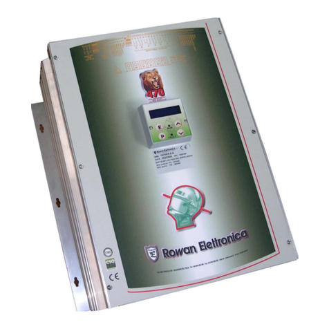
Rowan Elettronica 310S User manual

ROWAN ELETTRONICA s.r.l. -ViaUgoFoscolo,20 - 36030CALDOGNO - VI - ITALY
1/ 20
INSTRUCTION MANUAL
Code 310S
THREE-PHASE VOLTAGE REGULATOR
REV. 14 - Date 13/09/19
Motori, azionamenti, accessori e servizi per l'automazione
Via Ugo Foscolo, 20 - CALDOGNO - VICENZA - ITALY
Tel.: 0039 444 905566
Fax: 0039 444 905593 E-mail: [email protected]
Internet Address: www.rowan.it
EMC
CONFORMITY
Controllato/Approvato Data 13/11/06

ROWAN ELETTRONICA s.r.l. -ViaUgoFoscolo,20 - 36030CALDOGNO - VI - ITALY
2/ 20
WARNING
-Rowan Elettronica declines any responsabilities for possibile inexactitudes in the present manual, due
to printing or transcription errors and reserves the right to make, if necessary and without notice, any
variations needed for a better working of the product.
-Asconcernsthedataandthecharacteristicsmentionedinthismanual,amaxtolerance±10%isallowed.
-Electricalequipmentscancreatedangeroussituationsforpersonsandthings;theuserisresponsiblefor
theinstallation,operationandmaintenanceoftheequipmentandthecomplianceoftheinstallationtothe
standardsinforce.
-Onlyqualified personnel should work onthis equipment, and only afterbecoming familiar with all safety
instructions regarding installation, operation and maintenance procedures contained in this manual. In
case of doubts, contact Rowan Elettronica srl.
Code 310S
THREE-PHASEVOLTAGEREGULATOR
INDEX
Page
TECHNICALCHARACTERISTICS ...................................................................................................... 3
OVERALLDIMENSIONS ................................................................................................................... 3
PRINCIPLESANDCHARACTERISTICSOFOPERATION ................................................................. 4
DESCRIPTIONOFLEDINDICATORS................................................................................................ 4
MICROSWITCHES-LED’s-TRIMMERS SILKSCREEN ................................................................. 5
DESCRIPTIONOFPOWERTERMINALBLOCK................................................................................ 6
DESCRIPTIONOFCONTROLSTERMINALBLOCK .......................................................................... 6
DESCRIPTIONOFTRIMMERS .......................................................................................................... 7
DRIVESETTINGTABLE .................................................................................................................... 8
STANDARDSETTING ........................................................................................................................ 9
Descriptionofmicroswitchoperation andset-upforthevarious typesofload
(inductive-resistive)withopen-loopcontrolboard ............................................................................. 10
INSTRUCTIONSFORROWANMOTORCONNECTION ..................................................................... 11
POWER TERMINAL BLOCK CONNECTIONS................................................................................. 11
MOTORANCILLARYEQUIPMENTTERMINALBLOCKCONNECTION ............................................. 11
CLOSEDLOOPVOLTAGEREGULATOR.......................................................................................... 12
EXAMPLESOFAPPLICATION .......................................................................................................... 13
automatictemperaturecontrolthroughventilation............................................................................ 13
automatic temperature control through ventilation with display instrument .................................... 14
variable current and voltage stabilised power supply ..................................................................... 15
MECHANICALINSTALLATION........................................................................................................... 17
WIRINGSYSTEMAND(EMC)ELECTROMAGNETICCOMPATIBILITY ............................................. 17
CIRCUITSILKSCREEN ...................................................................................................................... 18
BLOCKDIAGRAM ............................................................................................................................. 19
INSTRUCTION MANUAL

ROWAN ELETTRONICA s.r.l. -ViaUgoFoscolo,20 - 36030CALDOGNO - VI - ITALY
3/ 20
TECHNICALCHARACTERISTICS:
-Voltageregulationontheload fromzeroto100%oflinevoltagewith3wire/3wirewithneutral/6wireconnection.
-SCR drive range up to a 200A line current on continuos service (on request until 700A).
-Selectablestandardthree-phasesupplyvoltage:170÷260VAC(indicatedby230)and300÷460VAC(indicatedby
400), 50-60Hz. Range 320÷485VAC (indicated by 440V) and 330÷500VAC (indicated by 460V) available on
request.
- Maximum accepted supply distorsion: 10%
-Drivesadjustablethroughmicro-switchesforvoltagecontrolof:Rowanmotors,Alquistmotors,fanswithmaxunit
power of 0,75Kw, transformers, electrical resistances and lamps.
-VoltageregulationbypotentiometerorDCsignal0÷+10VDCwithaccelerationanddecelerationrampsadjustable
byinternaltrimmers.
-Feedbacksignalinputadjustablefor0÷+10VDCor0÷4VACinputfromcurrenttransformerfortheclosed-loop
control of current or voltage.
-Capabilitytooperateunderautomatictemperaturecontrolwithreferencefromheatprobe.
-Inputs/outputsaregalvanicallyisolatedfromhighvoltageandcanbecontrolledbyPLC,programmablelogicor
otheranalogsignal.
-Protections:phasefailurewithoutputterminalsforanexternalemergencyrelay(24VDC/50mA);0.5Afastfuses
for driving circuit protection.
-LEDs indicating the following operation status: power on - phase failure - operation consent - operation - max
voltagefeedback.
-Plug-in type terminal block for input/output control connection.
-Operatingtemperature:-5°Cto+40°C(externaltocabinet);-5°Cto+55°C(internaltocabinet);
-Storingtemperature:-25°Cto+70°C
-Relative humidity: 5 to 95% (non condensing)
-Standardversioninaluminiumcontainerwithpolycarbonatelidcoverstencilledwithreferenceguidediagramsfor
operation checks and settings.
-IP 20 protection.
-Compliance with Standards: this equipment complies with standard CEI EN 60204-1. As regards Electro
MagneticCompatibility(EMC)inindustrialarea,thisequipmentcomplieswithstandardsEMC 2004/108/CE with
referenceto these standards:
> CEI EN 61800-3 when used as actuator (or speed regulator for electric motors);
> CEI EN 60947-4-3 when used as regulator (used without electric motors);
Tosatisfythesestandards,C310Smustbeconnectedwiththecorrectfilteringdevices,and installedinfull
compliancewith instructions reported on page 17.
OVERALLDIMENSIONS FIXTUREDRILLINGTEMPLATE
* With ventilation.
Ventilated sizes have a heat probe (maximum temperature + 80°C normally close contact, max 5A - 250Vac) to
be connected serially to the emergency circuit in order to leave out voltage to the regulator in case of over
temperature.
The fan and the heat probe must be connected by the terminal board outside the PVC grid (lower side).
ELBATEZIS
.DOC H B L A C D gk
0/S013 59 562 591 231 552 071 2
1/S013 051 562 032 061 752 591 4
2/S013 051 562 513 002 752 082 4,5
*3/S013 051 562 563 002 752 082 2,6
*4/S013 061 562 005 002 752 053 4,7
*5/S013 062 082 065 332 562 084 51
*6/S013 072 083 085 033 752 054 03

ROWAN ELETTRONICA s.r.l. -ViaUgoFoscolo,20 - 36030CALDOGNO - VI - ITALY
4/ 20
PRINCIPLES AND CHARACTERISTICS OF OPERATION
CODE310Regulatorisathree-phasevoltageregulatordesignedtocontrolanytypeofmixedresistive-inductive
balancedload;itisaveryversatileboardthatcanbeusedtocontrolthree-phasemotors,electricalresistances,
transformers, etc. Voltage regulation is by means of a phase partitioning system using controlled diodes (SCR
- silicon-controlled rectifiers), power components which ensure reliability in the event of overvoltages or
overcurrents. Actuation also involves a feedback input which allows certain parameters such as voltage,
current, temperature, speed and so on, to remain constant. It replaces the electromechanical phase changers
in the control of Alquist motors in coiling systems.
Note: in case supply voltage allows motor connection with delta configuration, it is possible to use the 6-wire type of
connection (see setting on page 7 and diagram on page 4); with this type of connection the maximum power of cod. 310S
can be multiplied by 1,73.
DESCRIPTIONOFLEDINDICATORS
L1 POWER ON
-LED on indicates power supply flowing through the board and driving circuits.
L2 RUN
-LED ON: indicates the presence of voltage on the load (increases luminosity as voltage increases).
-LED OFF: in case of ‘operation consent’ opening and ‘phase failure’ status intervention.
L3 MAXIMUM VOLTAGE FEEDBACK
-LEDONindicatesthatvoltageonfeedbackinput(terminal6)hasreachedthemaximumpossible;adjustP5so
that the system operates with maximum feedback signal and L3 nearly off.
L4 PHASE FAILURE
-LED on indicates phase failure on one supply phase or in the board internal transformers. Light-up of phase
failure status LED also statically removes voltage supply to motor (LED L2 ‘operation’ off) and excites any
emergencyrelayconnectedtoterminals 13-14.Toresetremoveandthenresumevoltagesupplytothe board.
L5RUNCONSENT
-LED ON: indicates closure of switching contact on terminals 4 - 12 and therefore consent to load voltage
regulation;
-LED OFF: indicates static zero-setting of board controls and of load voltage.
ELBATREWOPS013.DOC
REWOP SEZIS
DETAR TNERRUC
PILSHGIH SROTOM EVITSISER SDAOL **SNAF
dednamocceR esufdeyaled LGEPYT
ylppusnaF rewop esaC noitapissid TAEH EBORP ecneserp
rewopxam rewopxam rewopxam
AV*032 V*004 V*032 V*004 V*032 V*004
Wk Wk Wk Wk Wk Wk A W W
0/S013 21 5,1 3 5,4 8 3 5,5 02 / 06 on
1/S013 03 5,4 5,7 21 02 5,7 31 04 / 041 on
2/S013 83 5,5 01 51 52 01 5,81 05 / 081 on
3/S013 57 5,21 22 03 05 91 33 001 52 043 sey
4/S013 011 5,81 33 54 57 03 55 061 52 005 sey
5/S013 002 03 15 57 031 15 29 052 52 009 sey
6/S013 054 86 321 771 003 321 502 005 05 0051 sey
rewopCAV004eesylppusCAV064/044/514rof*-rewopCAV032eesylppusegatlovCAV042rof*
)srotomnoitcudnidradnats(Wk57,0nahtrewolebtsumsrotomelgnishcaerofrewopmumixamehtdaolsnafrof**

ROWAN ELETTRONICA s.r.l. -ViaUgoFoscolo,20 - 36030CALDOGNO - VI - ITALY
5/ 20
MICROSWITCHES - LEDs - TRIMMERS SILKSCREEN
6 WIRE CONNECTION DIAGRAM
(ONLY FOR LOADS WHICH CAN BE CONNECTED WITH D CONNECTIONS)
3 WIRE WITH NEUTRAL CONNECTION DIAGRAM
(FOR UNBALANCE LOADS)
THREE-PHASE
SUPPLY MOTOR BOARD
(or OTHER KIND OF LOAD)
THREE-PHASE
SUPPLY
LOAD
CONTROL TERMINAL BLOCK
POWER TERMINAL BLOCK
EMERGENCY
RELAY
THREEPHASE
LOAD
RUN
MAXFEEDBACK
LACKOF PHASE
RUNCONSENT
VOLTAGEON
THELOAD
FEEDBACK

ROWAN ELETTRONICA s.r.l. -ViaUgoFoscolo,20 - 36030CALDOGNO - VI - ITALY
6/ 20
DESCRIPTION OF POWER TERMINAL BLOCK
R1-S1-T1 Power supply three-phase line. Connect to threephase line supply with the EMC filter inductance as
describedonpage17(necessaryfortheCEmarking).Besuretosetupthevoltagechangerscorrectly beforegiving
powertotheseterminals(seebridgesCT1-CT2-CT3onsilkscreenonpage4).Iftypeoffunctioningn.5isused,
close microswitch S20 for power supply max 460V, open microswitch S20 for power supply max 260V.
Important:withpowersupply60Hzanddrivefunctioningwithopen-loopconfiguration,itisnecessarytore-adjust
the minimum by trimmer P8 (by increasing it) to obtain the correct set-point regulation range.
U1-V1-W1 Regulatedoutput to the load. Settheloadin star or delta connectionaccordingtomotor ratings and
power supply voltage.
PE Earth connection. It is necessary to connect the terminal PE to earth for safety and EMC compatibility
reasons.
DESCRIPTION OF CONTROLS TERMINAL BLOCK
1=Extreme
2=Extreme set-point potentiometer (standard 10K or any value within the 3K-100K range).
3=Cursor
2=reference voltage 10VDC Max 10mA for set-point potentiometer
4=common negative 0V
4-3 = set point analog voltage input 0 to +10VDC - 2mA
4-5 = ramp stop contact input
- closed: with the deceleration ramp set, zero-sets the set-point signal
- open: with acceleration ramp set, gives consent to set-point signal rise
4-6 = feedback signal input (feedback) settable for TA/TV input 4VAC/0.2A or DC/AC signal max50V
4=Extreme
7=Cursor minimum adjustment external potentiometer (10 Kohm).
8=Extreme
Setsafixedminimumvoltageontheloadirrespectiveoftheset-pointvalue(forexampleitdeterminesminimum
ventilation in the case of automatic temperature control); the potentiometer becomes operational by opening
microswitches S14 and S15.
9=Cursor
10=Extreme maximum adjustment external potentiometer (10 Kohm).
11= Extreme Regulates the maximum voltage value on the load irrespective of the set-point value; for
example it determines maximum ventilation in the case of automatic temperature control
through the fans. The regulation is activated by opening microswitch S18 and closing
microswitch S17.
4-12 = operation consent (open collector NPN transistor or open contact)
- closed: gives consent to load voltage regulation;
- open: statically removes load voltage and zero-sets the board controls (ramps, set-points ...).
13-14 = 24VDC - 50mA “phase failure” emergency relay coil power supply .
NOTE: for relay with incorporated diode, connect the positive to 13 and the negative to 14.

ROWAN ELETTRONICA s.r.l. -ViaUgoFoscolo,20 - 36030CALDOGNO - VI - ITALY
7/ 20
DESCRIPTION OF TRIMMERS
P1 - P2 - P3 - P4 - P17 Authorised personnel only.
P5 Regulates the feedback signal connected to terminal 6; set up in case of drive mode as close loop voltage
regulator(inclockwisedirectionthefeedbacksignalincreases);withterminal3at 10VDCand P9all inclockwise
direction, calibrate P5 until the set-point max range request. (P5 in clockwise direction decreases the max).
P6 Regulates deceleration ramp time in the following ranges:
MINIMUM MAXIMUM
S9 closed 0.20 sec 25 sec
S9 open 5 msec 500 msec
(in clockwise direction the ramp time increases).
P7 Regulates acceleration ramp time in the following ranges:
MINIMUM MAXIMUM
S9 closed 0.20 sec 25 sec
S9 open 5 msec 500 msec
(in clockwise direction the ramp time increases).
P8 Regulates the set-point minimum limit; (in clockwise direction the minimum limit increases).
P9 Regulates the set-point maximum limit; (in clockwise direction the maximum limit increases).
P10 Determines the maximum limit of motor voltage with blocked motor rotor on Alquist selection mode (see
presetting no 7 on page 7) (in clockwise direction the maximum limit increases); authorised personnel
only.
P11 Increases the integration of the response in case of closed-loop voltage regulation with feedback signal.
Rotate in a clockwise direction to smoothen oscillations if it was not possible to dampen them with trimmer
P13.
P12 Regulatestheproportionalactionincaseofclosed-loopvoltageregulationwithfeedbacksignal.Byrotating
in a clockwise direction it increases the voltage gain necessary for control and therefore accuracy. Rotate
counter-clockwise to smoothen the oscillations during operation if these were not successfully dampened
previously with trimmer P13 and then P11; it may be disconnect by microswitch S13 for the maximum
possible precision.
P13 Regulates the integral action in case of closed-loop voltage regulation with feedback signal. Rotate in a
clockwise direction to smoothen oscillations during operation.
P14 Regulatesafixedminimumvoltageontheloadirrespectiveoftheset-pointvalue.Forexampleitdetermines
minimum ventilation in the case of automatic temperature control through the fans. The regulation is
activatedbyclosingmicroswitchS14andopeningmicroswitchS15.Clockwiserotationincreasesminimum
voltage.
P15 Phase failure activation; authorised personnel only.
P16 Regulates the maximum voltage value on the load irrespective of the set-point value. For example it
determines maximum ventilation in the case of automatic temperature control through the fans. The
regulationisactivatedbyclosingmicroswitchesS17andS18(clockwiserotationincreasesmaximumlimit).

ROWAN ELETTRONICA s.r.l. -ViaUgoFoscolo,20 - 36030CALDOGNO - VI - ITALY
8/ 20
DRIVE SETTING TABLE
GUIDE FOR DRIVE SETTING SELECTION:
A) Choose one of the N° 1 - 2 - 3 setting option.
B) Choose one of the N° 4 - 5 - 6 - 7 setting option.
C) Choosetheramprangeonset-point(seen°8setting);formodesno5-6-7,rampshigherthan2sec.arerecommended.
D) In case of N°6 setting mode:
-Select the feedback signal type (n°9 setting)
-Choose whether inserting the internal or external regulation of the minimum output voltage U1 V1 W1; this value
is costant even if the feedback signal keeps load voltage at zero (typical application of ventilation control with
temperature probe feedback)
-Choose whether inserting the internal or external limitation of the maximum output voltage U1 V1 W1; this value
is costant even if the feedback signal keeps load voltage at maximum (typical application of ventilation control with
temperature probe feedback); standard setting: regulation not activated.
°N SGNITTES DESOLCORCIM )NO( NEPOORCIM )FFO(
1NOITCENNOCLARTUENTUOHTIWERIW3 2S-1S 5S-3S
2NOITCENNOCLARTUENHTIWERIW3 3S-2S 5S-1S
3NOITCENNOCERIW6 )DAOLNOITCENNOCATLEDELBALIAVAYLNOROF( 5S 3S-2S-1S
4ROTALUGEREGATLOVPOOLNEPO 61S-51S-21S-01S 91S-71S-11S-8S
5HTIWROTALUGEREGATLOVPOOLDESOLC LANGISREMROFSARTEGATLOVLANRETNI
V
XAM
CAV064 NO02SORCIM 91S-51S-21S-01S 61S-71S-11S-8S
V
XAM
CAV062 FFO02SORCIM
6HTIWROTALUGEREGATLOVPOOLDESOLC LANGISKCABDEEFLANRETXE
ELBANE21P )ELBATTESNIAG( 31S-01S-8S 61S-51S 71S-21S-11S 91S
ELBASID21P )TNATSOCNIAGXAM( 51S-01S-8S 61S 31S-21S-11S 91S-71S
7LORTNOCEUQROTTSIUQLA ROTOMNAWORHTIW
V
XAM
CAV064 NO02SORCIM 51S-21S-11S 91S 61S-01S-8S 71S
V
XAM
CAV062 FFO02SORCIM
8RELECED/RELECCA NOITCELESPMAR
PMARsm005/sm5 --- 9S
PMARs52/s2,0 9S ---
9EPYTLANGISKCABDEEF )6°NTUPNI(NOITCELES
VT/ATTUPNI A2,0CAV5,4 7S-4S ---
TUPNILANGISCA V05XAM 7S 4S
TUPNILANGISCD V05XAM --- 7S-4S
01 NOITAVITCAEGATLOVMUMINIMDAOL )NOITALITNEVMUMINIM(
41PHTIWLANRETNI 41S 51S
.TOPHTIWLANRETXE 8-7-4LANIMRETNO --- 51S-41S
DELBASID 51S ---
11 NOITAVITCAEGATLOVMUMIXAMDAOL )NOITALITNEVMUMIXAM(
61PHTIWLANRETNI 81S-71S ---
.TOPHTIWLANRETXE 11-01-9LANIMRETNO 71S 81S
DELBASID --- 71S

ROWAN ELETTRONICA s.r.l. -ViaUgoFoscolo,20 - 36030CALDOGNO - VI - ITALY
9/ 20
NOTE: N°5 SETTING remove the problem of the open-loop regulator which output voltage U1 V1 W1 can be affected
bycurrent/voltagephase-shiftduetoloadvariations(ininductiveloadsas electricmotors)bykeepingconstantthevoltage;
in addition, this setting mode keeps output voltage stable also in case of mains-line oscillations within the admitted supply
range (Warning: input line voltage must be greater than the output voltage to the load).
STANDARD SETTING
-3wireconnection withoutneutral(n°1operation mode)
-Open loop voltage regulator (settingn°4)
- Fast acceleration/deceleration ramp (500msec max).
- Closed micro: S1 - S2 - S10 - S12 - S15 - S16; the remaining ones are open.
OPEN-LOOP VOLTAGE REGULATOR
(standard Setting)

ROWAN ELETTRONICA s.r.l. -ViaUgoFoscolo,20 - 36030CALDOGNO - VI - ITALY
10 / 20
Descriptionof microswitch operationand set-up for the varioustypes of load
(inductive-resistive)withopen-loopcontrolboard.
Inthis case CODE 310S Regulator is set uptomanually regulate load voltage from zero to100%of line voltage.
Voltageatloadcanbeadjustedbypotentiometer,orbyDCsignalfrom0to10VderivedfromPLC,programmable
logic or other interface analog boards. If load insertions are frequent, it is convenient to use the starting contact
or open collector npn transistor (see controls terminal block 4-12 on page 6). Obviously the load is to be star or
delta-connected according to the value of the power supply line and to the load nameplate information.
Fans:INDUCTIVELOAD
CODE 310S actuation can be used to control the speed of fans driven by normal motors of unit power of up to
approximately 0.75kW. Its use with more powerful fans would cause normal motors to dangerously sustain
overcurrentatintermediatespeeds;thereforemore0.75kWfanscanbeconnectedinparallelchoosingactuation
setting that supports the overall power engaged. Typical use is in ventilation systems for industrial buildings or
shedsfor zootechnicalbreeding. Forfansgreater than0.-75kWitisadvisable toreplacethe normalmotorwitha
Rowantypeonewhicheliminatestheabove-mentionedinconveniencesorusingstandardDEFLATED motorsor
withSQUIRREL CAGE in SILUMIN.
In case of more fans connected in parallel with the possibility of group exclusion choose the open-loop voltage
operation mode with stabilized load voltage (see N°5 operation mode at page 8); in this way, it keeps the output
voltage stable even when the quantity of fans changes.
ElettricalResistance-Lamps:RESISTIVELOAD
CODE310Sactuatorcanbeusedtoregulatethetemperatureinhighpowerfurnaceschangingthevoltageatthe
electrical resistances wye-connected or delta-connected according to their supply voltage. In the 3-wire star
connectiontheloadmustbebalanced,otherwisewewouldhavedangerousovervoltageatthelowerpowerload
(voltageincreaseisproportionaltothepowerdifferenceoftheloadsconnectedtotheotherphases);byconnecting
theneutraltothewyecentreyoumayoperateevenwithunbalancedloadswithoutanyproblems(N°2OPERATION
MODE PAGE 8). With the load 6-wire delta-connected it is also possible to work with unbalanced loads. The
maximum power that may be applied to every single phase can be obtained from the actuator power divided by
3 (refer to the table on page 4). In case of 6-wire load connction the load power can be multiplied by 1.73.
Attention! sometimes it is necessary to adjust P4 all anti-clockwise to avoid that the load voltage gets 100%
without possibility to get back to zero volt.
Transformers-Alquist Motors-RowanMotors: INDUCTIVE LOAD
CODE310actuationmayalsobeusedtoregulatevoltageatthethree-phasetransformerprimary.Thisallowsits
applicationasAC/DClowvoltagepowersupplies,evenhighpowerones,withmanualregulationofoutputvoltage
with or without stabilization (see close loop voltage regulator).
NOTE:ForsomekindsofLoad, toavoid unbalancing of the line absorbtions near to the output max voltage, it is
necessary to OPEN micro S2 and adjust the Trimmer P4 all clockwise.
AnotherimportantapplicationofCODE310SactuationisvoltageregulationofALQUIST typeoperationmotors
(see setting N°7 on page 8).
LiketheRowanmotor,theAlquistmotoroperatesathighslips(evenwithblockedrotor),andwiththesamevoltage
atthestatorwindingsitstorqueincreasesasslipincreasesupto3timesthestartingtorque.Thepropertyofbeing
able to provide a sufficient area at constant power makes it particularly suitable in function as a winder in cases
where the ratio between the minimum and maximum diameter of the coil does not exceed 1/3. If the mechanical
systemhas agoodoutput efficiency(minimumfriction) thepullof thematerialto windwillremain constantasthe
coildiametervaries.Iftheratiobetweentheminimumdiameterandthemaximumdiameterofthecoilexceeds1/3
revert to servodiameter control system (like code 274S Rowan instrument).
Attention! Theuseof ROWANMOTORSinALQUISTMODEatfullvoltagecanbedoneonlyduringthestarting
phase inordertorapidlyacceleratein thepresence ofhighinertia.Thisvoltagevaluemustbelimited toa value
inconformitytoourdiagrams) necessarytokeepthecurrent(atlockedrotor)withinthemotorratedvaluereduced
of 15%.

ROWAN ELETTRONICA s.r.l. -ViaUgoFoscolo,20 - 36030CALDOGNO - VI - ITALY
11 / 20
INSTRUCTIONS FOR ROWAN MOTOR CONNECTION
POWER TERMINAL BLOCK CONNECTIONS
Evenifitpassesthroughspeedcontrolactuation,theconnectionremainsasanormalmotor,thereforeifthemotor
“nameplate”ratingstates:
HIGHSLIPMOTORSERVICETERMINALBOARDCONNECTION WITHOUTTACHOMETER
1-2 FAN
To these terminals it is necessary to convey the 230VAC voltage supply for
ventilation separated from the motor; be sure that this voltage is present also
when the motor is stopped so as to exploit also the down times. For cooling, in
some high power Rowan motors equipped with three-phase scroll fans, voltage
supply is conveyed directly to the fan motor terminal strip.
3-4 TEMPERATURE PROBE
Itis anormallyclosedcontactwhich opens whenthetemperatureofthe motorwindingsexceedssafetylimit class H(150°C).
It is used as an emergency measure for when the electromagnetic switch disconnects - note that the maximum current
carrying capacity of the contact is 1A - 230VAC.
Brake connection
connector or
terminal block
Powerterminal
block Service
terminalblock
400star/230deltamotor
with230line
connection is delta type
from operation of
terminal block U1 V1 W1
with400line
connection is star type
from operation of
terminal block U1 V1 W1
from operation of
terminal block U1 V1 W1
660star/400deltamotor
with400line
connection is delta type
HIGHSLIPMOTORSERVICETERMINALBOARDCONNECTIONWITHTACHOMETER
1 - 2 TACHOMETER (normally not used with C310 regulator)
3 - 4 FAN
5 - 6 TEMPERATURE PROBE
TACHO FAN TEMP.
PROBE
FAN
TEMP.
PROBE

ROWAN ELETTRONICA s.r.l. -ViaUgoFoscolo,20 - 36030CALDOGNO - VI - ITALY
12 / 20
CLOSED-LOOP VOLTAGE REGULATOR
(seesettingN°6page8)
DESCRIPTIONOFCLOSED-LOOPOPERATIONMODE
In this case the CODE 310 board supplies at load a regulated voltage which is the product of an analog process
thatmaintains the feedback magnitudeconstant(current,voltage, etc.) through thecontinuouscomparisonwith
thepotentiometerset-pointvalueor0to10Vanalog signal (see controls terminal block connection). In this case
the feedback input at terminal 6 is utilised, which must be enabled by the closure of microswitch S8, and set up
with microswitches S4-S7 for the following inputs:
- Input AC signal max 50V: micro S7 CLOSED - micro S4 OPEN
- Input DC signal max 50V: micro S4 - S7 OPEN
- Input TA (current transformer) or TV (voltage trasformer): micro S4 - S7 CLOSED
The amperometric transformers have a typical output at full scale 0.2A 4VAC, and have the following
characteristics with one wire crossing:
SETTINGRANGE SETTINGRANGE
TYPE151/110 TYPE150/150
plug 1-2 0-25A 0-200A
plug 1-3 0-50A 0-300A
plug 1-4 0-100A 0-400A
By performing several wire crossings you may modify the setting range thus adapting it to the various currents.
Forexample:with151/110typeTAplug1-2with5wirecrossings,thesettingrangewillbe0-5A(fullscaledivided
by the number of wire crossings).
It is possible to adjust the feedback signal with trimmer P5 (in clockwise direction the signal increases); with the
control terminal board 3 at 10VDC and P9 fully clockwise, calibrate P5 until the wished set-point max range is
performed (P5 in clockwise direction decreases the max); if led L3 lits on, the feedback signal is over-range.
Duringclosed-loopcontrolitmayhappenthatthesystemstartstohuntandgeneratesdangerousovervoltageson
the load. To stabilise control, rotate trimmer P13 clockwise, and if this is not enough first rotate trimmer P11
clockwise and then trimmer P12 counter-clockwise (minimum gain). Trimmers P13 and P11 affect the integral
actiontimes,whereastrimmerP12affectsthegainandthereforeclosed-loopcontrolprecision.Ifitwerenecessary
to modify the set-point setting range, regulate the minimum with trimmer P8 and the maximum with trimmer P9.
TA
FILTRO
EMC
+-
+
-
CONTROL TERMINAL
BLOCK
1° VERSION
CONTROL TERMINAL
BLOCK
2° VERSION
FEEDBACK
SIGNAL INPUT
THREE PHASE
BILANCED LOAD
fans
resistors
trasformators
Rowan motors
POWER TERMINAL BLOCK
TRANSDUCTOR
FEEDBACK
SIGNAL
RUN
EMC FILTER

ROWAN ELETTRONICA s.r.l. -ViaUgoFoscolo,20 - 36030CALDOGNO - VI - ITALY
13 / 20
EXAMPLES OF APPLICATION
WINDING/UNWINDING SYSTEM THROUGH MECHANICAL
FEELER PIN FOR SERVODIAMETER
InthisapplicationtheCODE310S operatesatcurrentCLOSED-LOOPcontrolthroughTA.Thecontrolledcurrent,
andthereforethetorque,isthatof the Rowan motor that must wind and unwind material, maintaining a constant
pullascoil diameter varies. This type ofcontrolinanycaseis used for winders; for unwinders itisusedwhenthe
ratio between the minimum and maximum diameter of the coil is greater than 1/3. Torque offset with diameter
variationisbroughtaboutwithamechanicalfeelerpinequippedwithservodiameterpotentiometerandaCODE276/
92interface board which supplies the torque signal to theCODE 310S board.
The PULL REGULATION POTENTIOMETER determines the pull on the material from maximum diameter to
minimum diameter. The MINIMUM PULL REGULATION potentiometer determines the pull on the material at
minimum diameter in order to offset the basic friction of the coil driving mechanisms.
The value of the DRUM POTENTIOMETER can be equal to or greater than 1 Kohm, and is to be mechanically
positioned so that at zero diameter the wiper is shortcircuited with the extreme connected at point 5.
Theminimum value of the PULLREG.andMINIMUM PULL REG.potentiometercan be equal toorgreaterthan
2Kohm, and insert a 10Kohm 1/4 Watt resistance in series with the wiper of each one as per layout.
In the event that continuous offset of minimum pull is not necessary you may omit connection to the relative
external potentiometer on the CODE 276/92 board, while fixed minimum pull can be regulated with trimmer P8
oftheCODE310Sboard.
ADJUSTMENTSEQUENCEonboardCODE276/92:Positionthefeelerpintomaximumdiameterandregulate
trimmer P2 of the CODE 276/92 board until output 11 (referred to terminal 5=0V) attains +10Vdc (LED L1 must
be faintly lit); if with trimmer P2 it were not possible to obtain maximum output adjust trimmer P0 ; position the
feeler pin for diameter zero and check that output 11 reads 0 Vdc.
Set up the microswitches as follows:
CODE310S S1 - S2 - S4 - S7 - S8 - S10 - S13 - S15 - S16 CLOSED
OTHERS: OPEN
CODE276/92 S4 CLOSED
OTHERS: OPEN
ThechoiceoftheplugonTA(oursupply)andofthenumberofwirecrossingsshouldbedoneinsuchawaythat
the frozen-rotor state motor current does not exceed 80% of the rated nominal value; thus consult the table on
page12.
EMC
FILTER
+-
Feeler pin for
servodiameter
POWERTERMINALBLOCK
CONTROL TERMINAL BLOCK
COIL
Drum
potentiometer MIN.PULL PULL
REGULATION

ROWAN ELETTRONICA s.r.l. -ViaUgoFoscolo,20 - 36030CALDOGNO - VI - ITALY
14 / 20
AUTOMATIC TEMPERATURE CONTROL THROUGH VENTILATION
Thislayoutisusedfortemperaturecontrolinzootechnicalandindustrialenvironments.CODE310S,inCLOSED-
LOOPconfiguration,isusedasaheatprobeforthecontrolofparallel-connectedfanshavingunitpowerofnotmore
than 0.75kW (see section about Fans on page 8); board CODE 251/92 acts as a transducer for the NI100 probe
andsuppliesanoutput (terminals 6-9) 0VDC at 0°C and +10VDC at 40°C.
AttheCODE310Scontrolterminalblockitismoreoverpossibletoconnectaminimumventilationpotentiometer
withwhichyoucansetfixedminimumventilationandfixedmaximum ventilationtolimitmaximumcooling-this
isdoneindependentlyofautomatic temperaturecontrol.
Set up the microswitches of the respective boards as follows:
CODE310S S1 - S2 - S8 - S10 - S13 - S15 - S19 - S20 CLOSED
OTHERS: OPEN
Regulate P12 full counter-clockwise, and regulate P11 clockwise in order that you obtain accurate temperature
control and free of any oscillations. If you wish to limit the setting range in the temperature set potentiometer,
regulatetrimmerP9forminimumset-upandtrimmerP8formaximumset-up(settingrangemin.0°Cmax.40°C).
NOTE:Setminimumtemperaturewhenthetemperaturesetpotentiometerwiperpointstowardstheendconnected
toterminal 2 (+10VDC);themaximum temperatureisobtainedwhen thepotentiometerwiperpoints towardsthe
endconnected toterminal1 (0VDC).
CODE 251/92 S10 - S11 CLOSED
OTHERS:OPEN
+-
HEAT PROBE
THREE-PHASE
FAN
Heat set
CONTROL TERMINAL BLOCK POWER TERMINAL BLOCK
Maximum
ventilation Minimum
ventilation EMC FILTER

ROWAN ELETTRONICA s.r.l. -ViaUgoFoscolo,20 - 36030CALDOGNO - VI - ITALY
15 / 20
AUTOMATICTEMPERATURECONTROLTHROUGHVENTILATION
WITHDISPLAYINSTRUMENT
This layout is used for temperature control in zootechnical and industrial environments. Board CODE 310S, in
OPEN-LOOPconfiguration,asavoltageregulatorforthecontrolofparallel-connectedfans havingunitpowerof
notmorethan0.75kW(seesectionaboutFansonpage8);thevoltagecontrol signal is supplied to board CODE
310SbypanelinstrumentCODE268,whichenablesenvironmenttemperatureandmaximumtemperaturealarm
thresholdto besetup anddisplayed;board CODE251/92acts asatransducer fortheNI100probe andsupplies
atoutput(terminals6-9)0VDCat0°Cand+10VDCat40°C.AttheCODE310Scontrolterminalblockitismoreover
possibletoconnectaminimumventilation potentiometerwithwhichyoucansetfixedminimum ventilationand
fixedmaximumventilationtolimitmaximumcooling-thisisdoneindependentlyofautomatictemperaturecontrol.
Set up the displays of instrument CODE 268 to show real temperature of the environment.
FurtherinformationaboutboardsCODE268andCODE251canbefoundintherespectiveinstructionsmanuals.
Set up the microswitches of the respective boards as follows:
CODE310S S1 - S2 - S10 - S12 - S15 - S19 CLOSED
OTHERS OPEN
Regulate trimmers P2 and P3 for minimum ramps (full counter-clockwise).
CODE268 S1 - S2 - S5 - S9 - S10 - S11 - S12 - S16 - S18 - S19 - S22 - S24 CLOSED
OTHERSOPEN
Adjust trimmers I and P/I of CODE 268 in order to avoid any hunting during ventilation.
CODE251/92 S10 - S11 CLOSED OTHERS OPEN
EMC
FILTER
+-
THREE-PHASEFAN
POWER TERMINAL BLOCK
CONTROL TERMINAL BLOCK
24VDC 50mA
relay
0÷100 °C
TEMP. PROBE
Maximum
ventilation Minimum
ventilation
Maximum
temperature
alarm

ROWAN ELETTRONICA s.r.l. -ViaUgoFoscolo,20 - 36030CALDOGNO - VI - ITALY
16 / 20
VARIABLECURRENTANDVOLTAGESTABILISEDPOWERSUPPLY
CODE310SinthiscaseisusedasanOPEN-LOOPvoltageregulatorattheprimaryofathree-phasetransformer.
Thevoltagecommandis supplied to board CODE 310S by two CODE 268 instruments whichoperateinclosed-
loopcontrolwithdirectvoltageandcurrent supplied at the load; the CODE 268 instruments, besides setting and
displayingcurrent and voltage,enableyouto utilise apresettablemaximumemergency threshold. Settingtakes
place with current priority, which means that in any case the load voltage is modified to maintain the preset
consumption constant, even in the event of a short circuit.
Set up the microswitches of the respective boards as follows:
CODE310S S1 - S2 - S10 - S12 - S15 - S16 CLOSED OTHERSOPEN
Note: for some kinds of load, it is necessary to open microswitch S2 and adjust trimmer P4 all clockwise in order to avoid
any network absorption unbalancing near to the maximum voltage at the output.
CODE268 CURRENT(max.SHUNTcurrentsignal60mVdc)
S1 - S7 - S8 - S9 - S18 - S19 - S21 - S23 CLOSED OTHERSOPEN
CODE 268 VOLTAGE (max.VOLTAGEsignal24Vdc)
S1 - S2 - S5 - S9 - S18 - S19 - S21 - S23 CLOSED OTHERSOPEN
InthiscaseCODE268instrumentsareset upto controla voltagenotgreaterthan24VDCwithaSHUNTcurrent
signalof 60mVdc; the minimumandmaximumvoltage and currentemergenciesareset for istantaneusrelease.
SetIandP/Itrimmersonfrontalboardofcode268toshutupundesiredovershoot.Forcalibrationorforanyother
setting for different voltages and currents refer to the CODE 268 manual.
CONTROL TERMINAL BLOCK POWER TERMINAL BLOCK
THREE-PHASE
TRANSFORMER
RUN
CURRENT SET-UP
VOLTAGE SET-UP
LOAD OUT
RUN
RUN
EMC
FILTER

ROWAN ELETTRONICA s.r.l. -ViaUgoFoscolo,20 - 36030CALDOGNO - VI - ITALY
17 / 20
MECHANICAL INSTALLATION
When installing the drive, follow the following precautions:
-Makesurethattheroominwhichitisinstalledcomplieswiththeenvironmentalspecificationsoutlinedonpage
3(temperature-humidity-degreeofprotection)
-Installitontheinternalcabinetplacededicatedtothepowerdevices,avoidingtobeneartotheanaloganddigital
low voltage devices.
-Maximize cooling air flow and avoid stacking drives. Leave a space of at least 100 mm under and above the
drive and at least 50 mm on the sides.
-Avoid excessive vibration and knocks.
-Leave space for any ‘anti EMI’ filters (see next paragraph).
WIRINGSYSTEMAND(EMC)ELECTROMAGNETICCOMPATIBILITY
To minimize interferences induced in the connections cables:
-Avoidpassingconnectionwiresofthecontrolorpowerterminalboardofthesamedriveorotherappliancesinto
the same duct.
-Connect analog inputs / outputs with screened cable.
-Connect one end of each screen singly to the common earth point of the control panel.
-Avoid earth rings.
-Equipmentcod.310Shasbeendesignedtooperateinindustrialarea,complyingwithrequirementsof ; for
thispurpose,thegeneralstandardCEIEN60204-1hasbeenapplied,whichcomplieswiththeessentialsafety
requirements of standard 89/392/CEE, modified by standards CEE 91/368 - 93/44 - 93/68.
AsregardsElectroMagneticCompatibility(EMC)inindustrialarea,thisequipmentcomplieswithstandardsEN
50081-2foremissionandEN50082-2forimmunityifconnectedwiththerelevantfilteringdevicesasindicated
intheconnectiondiagramreportedbelow,madewitha3-phase induction 0,5 mH.
Warning: to let the filter working correctly and for safety reasons, before giving voltage to the regulator,
connect thePEterminaltotheground.ConnectionsbetweenthefilterandtheR/S/Tterminalsmustbeas
shorter as possible and the sensitivity of the differential protection circuit must be higher than 0.3A.
*:only when used with the CXT.ROW0.15.400 filtering module.
The three CX=0,15mF (internal to the CXT.ROW0.15.440) have to be connected between the phases and put between regulator and
inductance filter; there is one header with plastic case where housing the three condensers.
Should you wish to fit a phase correction circuit (electronic phase partializing regulation generates harmonics,
especially the 3rd and 5th, on the power supply line), it must be fitted before the ANTI EMI filter, to prevent
cancellationoftheemissionreductioneffect.Theinstallationofphasecorrectioncapacitorsalsoreducesfurther
EMI emissions.
EMC
THREE-PHASE
RE-PHASING
EDOC
nI )A(retliF
DAOLFOEPYT
ROTOM REMROFSART EVITSISER
2C.taC 1C.taC 2C.taC 1C.taC 2C.taC 1C.taC
2,2.A21.TZR 21 SEY *SEY SEY *SEY *SEY ON
67,0.A53.TZR 53 SEY *SEY SEY *SEY *SEY ON
65,0.A05.TZR 05 SEY *SEY SEY *SEY *SEY ON
93,0.A27.TZR 27 SEY *SEY SEY *SEY *SEY ON
62,0.A601.TZR 601 SEY *SEY SEY *SEY *SEY ON
61,0.A561.TZR 561 SEY *SEY SEY *SEY *SEY ON
11,0.A542.TZR 542 SEY *SEY SEY *SEY *SEY ON
470,0.A073.TZR 073 SEY *SEY SEY *SEY *SEY ON
EMC
FILTER
THREE-PHASE
SUPPLY

ROWAN ELETTRONICA s.r.l. -ViaUgoFoscolo,20 - 36030CALDOGNO - VI - ITALY
18 / 20
CIRCUIT SILKSCREEN

ROWAN ELETTRONICA s.r.l. -ViaUgoFoscolo,20 - 36030CALDOGNO - VI - ITALY
19 / 20
BLOCK DIAGRAM
S19

ROWAN ELETTRONICA s.r.l. -ViaUgoFoscolo,20 - 36030CALDOGNO - VI - ITALY
20 / 20
Motori, azionamenti, accessori e servizi per l'automazione
Via Ugo Foscolo, 20 - CALDOGNO - VICENZA - ITALY
Tel.: 0039 444 905566
Fax: 0039 444 905593 E-mail: [email protected]
Internet Address: www.rowan.it
EMC
CONFORMITY
This manual suits for next models
7
Table of contents
Other Rowan Elettronica Controllers manuals
Popular Controllers manuals by other brands

NXP Semiconductors
NXP Semiconductors PCA9665 Product data sheet

Weinzierl
Weinzierl KNX IO 532 Operation and installation manual

Alcatel-Lucent
Alcatel-Lucent AOS-W 6.5.3.x user guide

InoTec
InoTec CPS 220/48.1 Series Mounting and operating instructions

TYROLIT Hydrostress
TYROLIT Hydrostress PPH40RR Series operating instructions

Identiv
Identiv Freedom Bridge installation guide