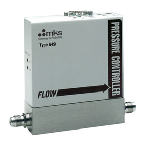
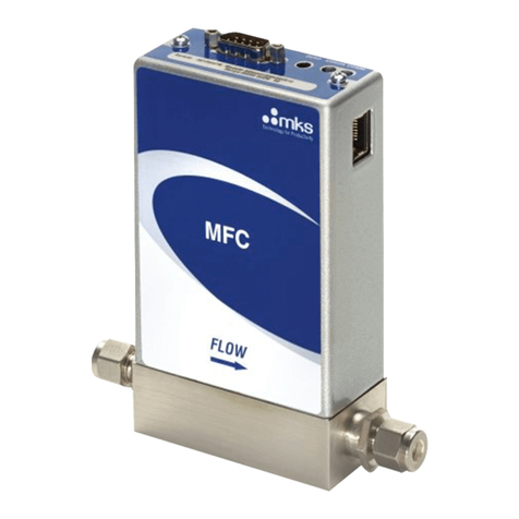
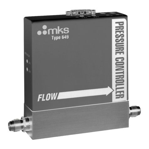
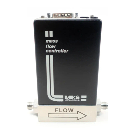
MKS 640A/641A User manual

Artisan Technology Group is your source for quality
new and certied-used/pre-owned equipment
• FAST SHIPPING AND
DELIVERY
• TENS OF THOUSANDS OF
IN-STOCK ITEMS
• EQUIPMENT DEMOS
• HUNDREDS OF
MANUFACTURERS
SUPPORTED
• LEASING/MONTHLY
RENTALS
• ITAR CERTIFIED
SECURE ASSET SOLUTIONS
SERVICE CENTER REPAIRS
Experienced engineers and technicians on staff
at our full-service, in-house repair center
WE BUY USED EQUIPMENT
Sell your excess, underutilized, and idle used equipment
We also offer credit for buy-backs and trade-ins
www.artisantg.com/WeBuyEquipment
REMOTE INSPECTION
Remotely inspect equipment before purchasing with
our interactive website at www.instraview.com
LOOKING FOR MORE INFORMATION?
Visit us on the web at www.artisantg.com for more
information on price quotations, drivers, technical
specications, manuals, and documentation
Contact us: (888) 88-SOURCE | sales@artisantg.com | www.artisantg.com
SM
View
Instra

116669-P1
Rev C, 12/99
Instruction Manual
MKS Type 640A/641A
Pressure Controller
Six Shattuck Road
Andover, MA 01810-2449
(800) 227-8766 or (978) 975-2350
Fax: (978) 975-0093
E-mail: mks@mksinst.com
Web site: http://www.mksinst.com

WARRANTY
Type 640A/641A Equipment
MKS Instruments, Inc. (MKS) warrants that the equipment described above (the
“equipment”) manufactured by MKS shall be free from defects in materials and
workmanship for a period of one year from date of shipment and will for a period of two
years from the date of shipment, correctly perform all date-related operations, including
without limitation accepting data entry, sequencing, sorting, comparing, and reporting,
regardless of the date the operation is performed or the date involved in the operation,
provided that, if the equipment exchanges data or is otherwise used with equipment,
software, or other products of others, such products of others themselves correctly
perform all date-related operations and store and transmit dates and date-related data
in a format compatible with MKS equipment. THIS WARRANTY IS MKS’ SOLE
WARRANTY CONCERNING DATE-RELATED OPERATIONS.
For the period commencing with the date of shipment of this equipment and ending one
year later in the case of defects in materials and workmanship, but two years later in the
case of failure to comply with the date-related operations warranty, MKS will, at its
option, either repair or replace any part which is defective in materials or workmanship
or with respect to the date-related operations warranty without charge to the purchaser.
The foregoing shall constitute the exclusive and sole remedy of the purchaser for any
breach by MKS of this warranty.
The purchaser, before returning any equipment covered by this warranty, which is
asserted to be defective by the purchaser, shall make specific written arrangements
with respect to the responsibility for shipping the equipment and handling any other
incidental charges with the MKS sales representative or distributor from which the
equipment was purchased or, in the case of a direct purchase from MKS, with the MKS
home office in Andover, Massachusetts, USA.
This warranty does not apply to any equipment which has not been installed and used
in accordance with the specifications recommended by MKS for the proper and normal
use of the equipment. MKS shall not be liable under any circumstances for indirect,
special, consequential, or incidental damages in connection with, or arising out of, the
sale, performance, or use of the equipment covered by this warranty.
MKS recommends that all MKS pressure and flow products be calibrated periodically
(typically every 6 to 12 months) to ensure accurate readings. When a product is
returned to MKS for this periodic re-calibration it is considered normal preventative
maintenance not covered by any warranty.
THIS WARRANTY IS IN LIEU OF ALL OTHER RELEVANT WARRANTIES,
EXPRESSED OR IMPLIED, INCLUDING THE IMPLIED WARRANTY OF
MERCHANTABILITY AND THE IMPLIED WARRANTY OF FITNESS FOR A
PARTICULAR PURPOSE, AND ANY WARRANTY AGAINST INFRINGEMENT OF
ANY PATENT.
12-99 116669-P1

116669-P1
Rev C, 12/99
MKS Type 640A/641A
Pressure Controller

Copyright © 1999 by MKS Instruments, Inc.
All rights reserved. No part of this work may be reproduced or transmitted in any form or by
any means, electronic or mechanical, including photocopying and recording, or by any
information storage or retrieval system, except as may be expressly permitted in writing by MKS
Instruments, Inc.
Baratron®is a registered trademark of MKS Instruments, Inc., Andover, MA
Cajon®is a registered trademark of Cajon Company, Macedonia, OH
Kalrez®and Viton®are registered trademarks of E. I. DuPont de Nemours and Co. Inc.,
Wilmington, DE
NUPRO®is a registered trademark of Crawford Fitting Company, Solon, OH
Swagelok®, VCR®, and VCO®are registered trademarks of Swagelok Marketing Co., Solon,
OH
Inconel®is a registered trademark of Inco Alloys International, Inc., Huntington, WV
Chemraz®is a registered trademark of Greene, Tweed, & Co., Inc., Kulpsville, PA
Kel-F®is a registered trademark of 3M Company, Minneapolis, MN

Table of Contents
iii
Table of Contents
Pressure Transducer Safety Information.................................................................................. 1
Symbols Used in This Instruction Manual.................................................................. 1
Symbols Found on the Unit ....................................................................................... 2
Safety Procedures and Precautions............................................................................. 3
Chapter One: General Information......................................................................................... 5
Introduction............................................................................................................... 5
How This Manual is Organized.................................................................................. 6
Manual Conventions ..................................................................................... 6
Customer Support...................................................................................................... 7
Chapter Two: Installation......................................................................................................9
How To Unpack the 640 Series Controller................................................................. 9
Unpacking Checklist ..................................................................................... 9
Product Location and Requirements........................................................................... 10
Interface Cables ......................................................................................................... 11
Generic Shielded Cable Description .............................................................. 12
The I/O Connector..................................................................................................... 13
Gas Pressure and Control........................................................................................... 15
Pressure Limits.............................................................................................. 15
Installing the Unit.......................................................................................... 15
Dimensions................................................................................................................ 17
Side Port Version.......................................................................................... 17
Down Port Version........................................................................................ 19
Side Port Controller Mounting Instructions................................................................ 21
Fittings.......................................................................................................... 21
Mounting Hardware ...................................................................................... 21
Down Port Controller Mounting Instructions ............................................................. 22
How To Connect the C-Seal Fittings............................................................. 23
How To Connect the W-Seal (SEMI 2878.3) Fittings.................................... 26
How To Connect the Z-Seal (SEMI 2878.2) Fittings ..................................... 28

Table of Contents
iv
Initial Configuration...................................................................................................31
Chapter Three: Overview.......................................................................................................33
General Information ...................................................................................................33
Pressure Control Range..................................................................................33
A Typical Control System..............................................................................34
How The 640 Series Pressure Controller Works .........................................................35
Tuning the 640 Series Pressure Controller..................................................................36
Proportional Term..........................................................................................36
Integral Term.................................................................................................37
Tuning the 640 Controller..............................................................................38
Priority of Commands................................................................................................40
Trip Points .................................................................................................................41
Action of the Trip Points................................................................................41
Applications with a Large Differential Pressure..........................................................42
Labels ........................................................................................................................42
Chapter Four: Operation ........................................................................................................43
How To Check the Zero .............................................................................................43
How To Zero a Type 640 (Absolute) Unit......................................................43
How To Zero a Type 641 (Gage) Unit............................................................44
How To Adjust the Span ............................................................................................45
How To Tune the 640 Series Controller......................................................................45
How To Adjust the Trip Point Values.........................................................................46
How To Select the Trip Point Action..........................................................................47
How To Use Trip Points as Error Indicators ...............................................................49
How To Change the Pressure Output Signal Range ....................................................50
How To Select Upstream Control...............................................................................51
Appendix A: Product Specifications.......................................................................................53
Performance Specifications ........................................................................................53
Environmental Specifications.....................................................................................54
Trip Point Specifications............................................................................................54
Physical Specifications...............................................................................................55
Appendix B: Valve Orifice Selection.....................................................................................57

Table of Contents
v
General Information................................................................................................... 57
Checking the Orifice Size.............................................................................. 57
How To Verify the Orifice Selection.......................................................................... 58
Using Different Gases ................................................................................... 60
Appendix C: Gas Density Table............................................................................................ 63
Appendix D: Model Code Explanation.................................................................................. 67
Model Code Description............................................................................................ 67
Index...................................................................................................................................... 73

Table of Contents
vi

List of Fi
g
ures
vii
List of Figures
Figure 1: Downstream Pressure Control ................................................................................ 16
Figure 2: Upstream Pressure Control..................................................................................... 16
Figure 7: Front and Back Views of the Side Port 640 Series Controller................................. 17
Figure 8: Side View of the 640 Series Controller................................................................... 18
Figure 3: Top View of the Down Port Type 640 Controller................................................... 19
Figure 4: Front and Side View of the Down Port Type 640 ................................................... 19
Figure 5: Bottom View of the Down Port 640 ....................................................................... 20
Figure 6: Bottom View of the Down Port Seals..................................................................... 20
Figure 9: Bottom View of the Side Port 640 Series Controller............................................... 21
Figure 10: Exploded View of the C-Seal Components........................................................... 24
Figure 11: Exploded View of the W-Seal Components.......................................................... 26
Figure 12: Exploded View of the Z-Seal Components ........................................................... 28
Figure 13: Top View of the 640 Series Controller.................................................................. 33
Figure 14: Sample Pressure Control System.......................................................................... 35
Figure 15: Effects of the Proportional Control....................................................................... 36
Figure 16: Effects of the Integral Control .............................................................................. 37
Figure 17: Controller Response with Initial P Term and I Term Values................................. 38
Figure 18: Controller Response with Increased P Term ......................................................... 39
Figure 19: Controller Response with Increased I Term .......................................................... 39
Figure 20: Serial Number Label............................................................................................. 42
Figure 21: Jumper Positions on the Transducer Board........................................................... 47
Figure 22: Jumper Positions on the Control Board................................................................. 51
Figure 23: Model Code Explanation...................................................................................... 57
Figure 24: Flow Range Selection........................................................................................... 59

List of Figures
viii

List of Tables
ix
List of Tables
Table 1: Definition of Symbols Found on the Unit .....................................................................2
Table 2: Interface Cables..........................................................................................................11
Table 7: I/O Connector Pinout..................................................................................................13
Table 3: Fitting Dimension.......................................................................................................17
Table 4: SEMI Specifications for Down Port Fitting Options ...................................................22
Table 5: SEMI 2787.1 C-Seal Retainer (EG&G Part Numbers)................................................23
Table 6: 0.445 Inch Diameter C-Seal Retainer.........................................................................23
Table 8: Initial Configuration...................................................................................................31
Table 9: Highest Pressure Suggested for Zero Adjustment of an Absolute Transducer..............44
Table 10: Orifice Size...............................................................................................................57
Table 11: Valve Orifice Index Number.....................................................................................58
Table 12: Pressure Range Selection..........................................................................................68
Table 13: Fitting Type Selection...............................................................................................68
Table 14: Valve Type...............................................................................................................69
Table 15: Seal Material Selection.............................................................................................69
Table 16: Valve Orifice Size Selection .....................................................................................70
Table 17: Trip Point Model Code Entry....................................................................................70
Table 18: Valve Plug Material..................................................................................................71

List of Tables
x

Pressure Transducer Safety Information S
y
mbols Used in This Instruction Manual
1
Pressure Transducer Safety Information
Symbols Used in This Instruction Manual
Definitions of WARNING, CAUTION, and NOTE messages used throughout the manual.
Warning The WARNING sign denotes a hazard to personnel. It calls
attention to a procedure, practice, condition, or the like,
which, if not correctly performed or adhered to, could result
in injury to personnel.
Caution The CAUTION sign denotes a hazard to equipment. It calls
attention to an operating procedure, practice, or the like, which, if
not correctly performed or adhered to, could result in damage to or
destruction of all or part of the product.
Note The NOTE sign denotes important information. It calls attention to a
procedure, practice, condition, or the like, which is essential to highlight.

Symbols Found on the Unit Pressure Transducer Safet
y
Information
2
Symbols Found on the Unit
The following table describes symbols that may be found on the unit.
Definition of Symbols Found on the Unit
|
On (Supply)
IEC 417, No.5007 Off (Supply)
IEC 417, No.5008 Earth (
g
round)
IEC 417, No.5017
Protective earth
(
g
round)
IEC 417, No.5019
Frame or chassis
IEC 417, No.5020 Equipotentiality
IEC 417, No.5021 Direct current
IEC 417, No.5031 Alternatin
g
current
IEC 417, No.5032
Both direct and
alternatin
g
current
IEC 417, No.5033-a Class ll equipment
IEC 417, No.5172-a
Three phase
alternatin
g
current
IEC 617-2 No.020206
Caution, refer to
accompanyin
g
documents
ISO 3864, No.B.3.1
Caution, risk of
electric shock
ISO 3864, No.B.3.6 Caution, hot surface
IEC 417, No.5041
Table 1: Definition of Symbols Found on the Unit

Pressure Transducer Safety Information Safet
y
Procedures and Precautions
3
Safety Procedures and Precautions
Observe the following general safety precautions during all phases of operation of this
instrument. Failure to comply with these precautions or with specific warnings elsewhere in
this manual violates safety standards of intended use of the instrument and may impair the
protection provided by the equipment. MKS Instruments, Inc. assumes no liability for the
customer’s failure to comply with these requirements.
DO NOT SUBSTITUTE PARTS OR MODIFY INSTRUMENT
Do not install substitute parts or perform any unauthorized modification to the instrument.
Return the instrument to an MKS Calibration and Service Center for service and repair to ensure
that all safety features are maintained.
SERVICE BY QUALIFIED PERSONNEL ONLY
Operating personnel must not attempt component replacement and internal adjustments. Any
service must be made by qualified service personnel only.
USE CAUTION WHEN OPERATING WITH HAZARDOUS MATERIALS
If hazardous materials are used, users must take responsibility to observe the proper safety
precautions, completely purge the instrument when necessary, and ensure that the material used
is compatible with the materials in this product, including any sealing materials.
PURGE THE INSTRUMENT
After installing the unit, or before removing it from a system, purge the unit completely with a
clean, dry gas to eliminate all traces of the previously used flow material.
USE PROPER PROCEDURES WHEN PURGING
This instrument must be purged under a ventilation hood, and gloves must be worn for
protection.
DO NOT OPERATE IN AN EXPLOSIVE ENVIRONMENT
To avoid explosion, do not operate this product in an explosive environment unless it has been
specifically certified for such operation.
USE PROPER FITTINGS AND TIGHTENING PROCEDURES
All instrument fittings must be consistent with instrument specifications, and compatible with the
intended use of the instrument. Assemble and tighten fittings according to manufacturer's
directions.

Safety Procedures and Precautions Pressure Transducer Safet
y
Information
4
CHECK FOR LEAK-TIGHT FITTINGS
Carefully check all vacuum component connections to ensure leak-tight installation.
OPERATE AT SAFE INLET PRESSURES
Never operate at pressures higher than the rated maximum pressure (refer to the product
specifications for the maximum allowable pressure).
INSTALL A SUITABLE BURST DISC
When operating from a pressurized gas source, install a suitable burst disc in the vacuum system
to prevent system explosion should the system pressure rise.
KEEP THE UNIT FREE OF CONTAMINANTS
Do not allow contaminants to enter the unit before or during use. Contamination such as dust,
dirt, lint, glass chips, and metal chips may permanently damage the unit or contaminate the
process.
ALLOW PROPER WARM UP TIME FOR TEMPERATURE-CONTROLLED UNITS
Temperature-controlled units will only meet specifications when sufficient time is allowed for
the unit to meet, and stabilize at, the designed operating temperature. Do not zero or calibrate the
unit until the warm up is complete.

Chapter One: General Information Introduction
5
Chapter One: General Information
Introduction
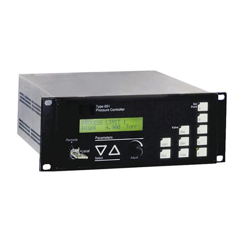
The 640A Series Pressure Controllers include the Type 640 absolute pressure controller and the
Type 641 gage pressure controller. The 640 Series Controllers consist of a Baratron®
capacitance manometer (either absolute or gage pressure), a normally closed proportional control
valve, and closed-loop control electronics. The closed-loop control circuitry enables the unit to
function as a proportional-integral (PI) controller. The unit’s compact size and small, three-inch
footprint reduce space requirements.
The 640 Series offers a variety of options including the seal material, full scale range, and
calibration. The seal material is available in an elastomer (Kalrez®, Viton®, Kel-F®, or
Chemraz®, refer to Appendix D: Model Code Explanation, page 67, for information) or all-
metal material. Full scale ranges are available from 10 Torr to 100 psi with a flow capacity of 50
sccm (standard cubic centimeters per minute) to 50 slm (standard liters per minute).
The 640 Series Pressure Controller can be used in either upstream or downstream pressure
control applications. The transducer inlet port is identified as the “Controlled Pressure Port”to
ensure that you install the 640 Pressure Controller into your system correctly.
The 640 Series Controllers provide two user-settable alarm trip points. The trip points can be set
from 1 to 100% of full scale. Each trip point controls an open collector transistor. An LED light
located on the top of the unit, indicates the trip point status.
Note The proportional control valve in the 640 Pressure Controller is not a
positive shutoff valve. Depending upon your application, you may need
to install a separate positive shutoff valve.

How This Manual is Organized Cha
p
ter One: General Information
6
How This Manual is Organized
This manual provides instructions on how to set up and install a 640 Series unit.
Before installing your 640 Series unit in a system and/or operating it, familiarize yourself
with all precautionary notes in the Safety Messages and Procedures section at the front of
this manual. Observe and obey all WARNING and CAUTION notes provided in the manual.
Chapter One: General Information, (this chapter) introduces the product and describes the
organization of the manual.
Chapter Two: Installation, explains the environmental requirements and describes how to mount
the instrument in your system.
Chapter Three: Overview, gives a brief description of the instrument and its functionality.
Chapter Four: Operation, describes how to use the controller with all its functions and features.
Appendix A: Product Specifications, lists the specifications of the instrument.
Appendix B: Valve Orifice Selection, presents the information used to select the appropriate flow
range for nitrogen and other gases.
Appendix C: Gas Density Table, lists the standard density of commonly used gases.
Appendix D: Model Code Explanation, explains how the model number of your 640 controller
lists the features included in the unit.
Manual Conventions
The following conventions apply throughout this manual:
XXXXXX For inputs: Indicates that the line must be pulled low to activate the function.
XXXXXX For outputs: Indicates that the output is active low.

Chapter One: General Information Customer Su
pp
ort
7
Customer Support
Standard maintenance and repair services are available at all of our regional MKS Calibration
and Service Centers listed on the back cover. In addition, MKS accepts the instruments of other
manufacturers for recalibration using the Primary and Transfer Standard calibration equipment
located at all of our regional service centers. Should any difficulties arise in the use of your 640
Series instrument, or to obtain information about companion products MKS offers, contact any
authorized MKS Calibration and Service Center. If it is necessary to return the instrument to
MKS, please obtain an ERA Number (Equipment Return Authorization Number) from the MKS
Calibration and Service Center before shipping. The ERA Number expedites handling and
ensures proper servicing of your instrument.
Please refer to the inside of the back cover of this manual for a list of MKS Calibration and
Service Centers.
Warning All returns to MKS Instruments must be free of harmful,
corrosive, radioactive, and toxic materials.
Table of contents
Other MKS Controllers manuals

MKS
MKS 900 Series User manual

MKS
MKS Oriel Instruments 3502 User manual

MKS
MKS Mass-Flo 1479A User manual

MKS
MKS 250E User manual

MKS
MKS 959 Series User manual

MKS
MKS Mass-Flo 1679B User manual

MKS
MKS 340001 User manual

MKS
MKS Granville-Phillips 358 series User manual

MKS
MKS Mass-Flo 1500 Series User manual

MKS
MKS 153D User manual