Rowan Elettronica 340G User manual

RowanElettronicaS.r.l. www.rowan.it Tel.+39-0444.905566
pag.1
Introduction
The340Ginvertersallowanefficientandflexiblecontrolofmotorspeed.Inthisway,
the asynchronous motor can be used in a wider range of applications.
The functioning interface is made of a panel consisting of six keys, one display with
five7-segmentdigitsandsevenleds.
Thedisplayandthekeysallowyoutochangealltheinverterparameterssoastomake
it suitable to all applications.
Thedrivedisplayallowsthemonitoringofcontrolledvariablesasfrequency,current,
output voltage, cos phi, power and the storage of the last 4th alarms attempted.
QUICK START
340G
SeriesDigitalInverter
Warning
Electricalequipmentcanbehazardoustopersonalsafety.Itisessentialtobefully
acquaintedwiththeoperatinginstructionsandcontrolsofelectricalequipmentbefore
attempting to operate it.
Equipmentmustonlybeusedbytechnicalpersonnelwhoarequalifiedtodoso,who
are fully acquainted with the standards for installing and operating equipment in
compliancewithallapplicablesafetystandards,andwhoareabletofullyunderstand
allsafety-relatedwarnings.
Capacitorsinsidetheequipmentoperateatdangerouslyhighvoltages.Alwayswait
atleast5minutesaftertheequipmenthasbeenswitchedoffbeforeperforming
anyworkonit.Dangerousvoltagesmaybepresentatthepowerterminalsevenwith
the motor stopped. These are terminals U, V, W, L1, L2.
Under certain control program conditions, the machine can re-start automatically
afterapowerfailure.
Therearenouserserviceablecomponentsinsidetheequipment.Onlytheterminal
covermustberemovedduringinstallation.
··
··
·
··
··
·
··
··
·
··
··
·

RowanElettronicaS.r.l. www.rowan.it Tel.+39-0444.905566
pag.2
egatlovtupnI ]CAV[
retrevnI rewop ]AVk[
lanimoN tuptuo tnerruc ]A[
esahP tnerruc V032 ]A[
esahP tnerruc V004 ]A[
rotoM rewop V004 ]Wk[
P.A.3/G043
%51-V032 %01+V084 zH06-05 -eerhT esahp
0,50,79,70,90,3
EMC
340G inverteris fittedwithaninternalEMCfilter(EN55011Cl.A) asstandard.
Thisdatasheetprovidesaquickguidetotheinstallationand
operation of the inverter. For advanced functions and for
maximumsafety,alwaysrefertothecompletemanual,available
on request.
Technical specifications
WIRINGDIAGRAMS
Powerterminals
L2
L1
L3
-
PE1
U
V
W
R
+
(at ground point)
RM
BRAKING
RESISTANCE THREE
PHASE
MOTOR
POWER SUPPLY
Three phase 50 Hz/60 Hz +/- 5%
230 V (-15%) to 480 V (+10%)
EARTH 1 2 3 4 5 6 7 8 9

RowanElettronicaS.r.l. www.rowan.it Tel.+39-0444.905566
pag.3
REV.0 06/06/05
POWERCONNECTIONS
TERMINALS
PE1
L1
L2
L3
FUNCTION
GROUND POINT EARTH
THREE PHASE
MAINS POWER SUPPLY
N.
-
R
+
U
V
W
1
2
3
4
5
6
7
8
9
DC stage negative
BRAKING RESISTANCE
DC stage positive
THREE PHASE OUTPUT
(TO MOTOR)
Controlterminals
RLA
Programmable
Output
Earth
A1 A2 A3 1 2 3 4 5 6 7 8 9 10 11 12
(Input configuration
for PNP controls. Can
also be configured for
NPNorexternalfeed.)
Alarm
DIG. INPUT 1 [Run]
DIG.INPUT2[Rev]
DIG. INPUT 3 [Freq. sel1]
DIG. INPUT 4 [Freq. sel2]
+24V
COM-IN Digital inputs
0V 24- GND Digital Outputs
B1 B2 B3 13 14 15 16 17 18 19 20 21 22 23 24
DIGITALINPUT5[FreqSel3]
DIGITALINPUT6[JOG]
AnalogInput2N
AnalogInput2P
V-
FB+
FB-
V+
COMDig.out.
+10VOUT
Potentiometer R
min. 4,7 kOhm
+ -
AnalogInput1
0V-GNDAn.Input
LOAD
AnalogOutput
+24V
LOAD
Digitalout.1
Digitalout.2
RLB

RowanElettronicaS.r.l. www.rowan.it Tel.+39-0444.905566
pag.4
CONTROLCONNECTIONS
Strip 1
A1
A2
A3
B1
B2
B3
1
2
3
4
5
6
7
8
9
10
11
12
Name
Digital Output RLA - NO
Digital Output RLA -COM
Digital Output RLA - NC
Digital Input 1
Digital Input 2
Digital Input 3
Digital Input 4
COM-IN Digital Inputs
+ 24V OUT
0 V 24 - GND Dig. Inputs
Enc.
-10V
Digital Output RLB - NO
Digital Output RLB -COM
Digital Output RLB - NC
Digital Input 6/B+
Digital Input 5/A+ Enc.
/B- Enc. Ch.
Analog Input 2N/A- Enc.
Analog Input 2P
Function
Programmable relay digital output
R
Programmable digital input
Digital inputs power
+ 24 V potential
0 V 24 reference for digital inputs
Encoder input channel B+
Encoder input channel A -
Enc. Channel A -
[I 102=3] Motor running
[I 000=1]
[I 001=
[I 002=7] Freq sel 1
[I 003=8]
-
/
elay digital output
Programmable digital input /
Programmable digital input / Encoder input channel A+
10 V potential /
Programmable analog input 2
Programmable analog input 2 Enc. Channel A -
[I 103=1] Alarm state
Run
2] Reverse
Freq sel 2
[I 005]
[I 004]
[I 210=0] +-10 V
[I 210=0] +-10 V /
Max
230V AC 0,2A
125V AC 0,3A (UL rating)
110V DC 0,3A (UL rating)
30V DC 1A (UL rating)
230V AC 0,2A
125V AC 0,3A (UL rating)
110V DC 0,3A (UL rating)
30V DC 1A (UL rating)
6mA @ +24V
-
+24V / 300mA
-
HTL 24V / 17mA
TTL 5V / 9mA
-
6mA @ +24V
6mA @ +24V
6mA @ +24V
10V / 50mA
+/-10V / 0.5mA
Strip 2
13
14
15
16
17
18
19
20
21
22
23
24
Name
V-
FB+
FB-
V+
Digital Output 1
Digital Output 2
+ 10V OUT
GROUND REF
COM Digital outputs
Analog Output 1
0 V - GND Analog input
Analog Input 1
Function
Ground / 0V / V-
Ground (earth) reference for cable shielding
External positive supply
B
Common potential for digital outputs (open collector)
Programmable open collector digital output
Programmable analog output
0 V potential for analog inputs/outputs
[I 100=0]Drive ready
[I 101=6]Steady state
[I 300=0] Freq.out abs
=0
us line (dominant high)
Bus line (dominant low)
Programmable analog input 1
+ 10 V potential
[I 200 ] +/- 10 V
Max
-
+/-10V / 0.5mA
+10V / 50mA
+50V / 50mA
+/-10V / 5mA
-
+11V.....30V
-
-
0V
+/-10V / 5mA
-
JUMPERSANDCONNECTORS
CONNECTOR J6 FOR
PROGRAMMING KEY
ControlBoard
TERMINALS
CONNECTOR J1: (Analog
Input 1 - terminal 23)
(default) 0 -10V or +/-10V
0-20mA or 4-20mA
J4
J5
J6 J1 J3
J2
CONNECTOR J3: (Analog
Output - terminal 21)
(default) 0 -10V
+/-10V
CONNECTOR J2:(Analog
Input2P- terminal 12)
(default) 0 -10V or +/-10V
0-20mA or 4-20mA
CONNECTOR J5:( terminal 10)
(default) -10V
B- Encoder channel
CONNECTOR J4:( terminal 11)
(default) Analog Input 2 N
A- Encoder channel

RowanElettronicaS.r.l. www.rowan.it Tel.+39-0444.905566
pag.5
DIMENSIONS
Starting
1-
Connect a potentiometer (minimum resistance 4.7 kOhm) to provide a speed reference
(terminals 22, 23, 24).
2- Power down the digital inputs ( terminal 5) to 0V 24-GND digital outputs (terminal 7).
3 - Connect two contacts for the start and reverse commands (terminals 1, 2, and 6).
4 - Close the start contacts to start the motor. The motor starts and follows the programmed
ramp up to the preset frequency (default S-300= S301=5 seconds).
Stopping
To stop the motor:
1 - Deactivate the start command to stop the motor with the default ramp (
S301
= 5
seconds from maximum frequency to 0 Hz).
2- Alternatively, set the speed reference potentiometer to zero to control motor slowing
manually.
Warning!If you stopthe motorinthis way,the motorremainslive evenwhen stopped.
Modifying control parameters
Let us assume that we have switched the inverter on and that we need to change the
motor's maximum frequency from 50 Hz (the factory default) to 60 Hz.
The display shows 00 when switched on. Press Mrepeatedly to display the Smenu ( S-
000 ). Use the Ý, ß keys to select code 201 ( S-201 ) and press E.The S-201 (maximum
frequency) parameter value appears. If the PRG LED is lit and steady, the parameter can
be modified. Press Ý until the display shows 60.0. Then press Eto confirm and enter the
new value. See point 14 in the table below to store parameters permanently.
If the motor fails to start
If the motor fails to start when you give the start command, first check that the connections
have been made correctly, then check that the default inverter parameters actually suit
the characteristics of the motor installed.
··
··
·
··
··
·
··
··
·
··
··
·
A
B
C
D
E
SIZE
145
260
165
120
251

RowanElettronicaS.r.l. www.rowan.it Tel.+39-0444.905566
pag.6
Setting sequence
Go to the S - Startup menu
Inverter mains voltage
Inverter mains frequency
Maximum inverter output
voltage
Nominal motor frequency
Nominal motor current
Motor pole pairs
Motor power factor
Command mode
Maximum reference frequency
Reference source
Inverter ramp up and down
times
Motor stator resistance
autocalibration
Save parameters
Description
Press "M" to display the Startup menu.
Set the inverter mains voltage in parameter S.000: 230V,
400V and 460V for 340G.
Set the inverter mains frequency in parameter S.001: 50Hz or
60Hz.
Set the maximum voltage for inverter output to the motor
(plated value) in parameter S.100.
Set the nominal motor frequency (plated value) in parameter
S.101.
Set the nominal motor current (plated value) in parameter
S.150.
Set the number of motor pole pairs (poles/2) in parameter S.151.
Set the motor power factor (cosj) (plated value) in
parameter S.152.
Set the command mode in parameter S.200:
- [1] = Terminals - commands from terminals (default)
Set the inverter's maximum reference frequency (analog
reference) in parameter S.201.
Set the source of the inverter reference frequency in
parameter S.202 :
- [1] = 0-10V reference on AN IN1 terminal 30 (default)
- [2] = +/-10V reference on AN IN2 terminal 27
Set the ramp up time in parameter S.300.
Set the ramp down time in parameter S.301.
Enable motor stator resistance autocalibration in parameter
S.900:
- "do" appears on the 7 segment display when enabled.
Enable parameter saving in the inverter's non-volatile
memory in parameter S.901.
1
2
3
4
5
6
7
8
9
10
11
13
14
12
START-UP
PROGRAMMING KEY: Operating instructions
Transferring parameters from the key to the inverter:
- Remove the key connector cover and insert the key.
- From the keyboard select parameter C - 040,select do then press E.
The "donE" message is displayed for 2 seconds to confirm that the operation has terminated
successfully.

RowanElettronicaS.r.l. www.rowan.it Tel.+39-0444.905566
pag.7
List of main parameters (seethe manualfor thecomplete list):
Code Description (unit of measure)
D - DISPLAY menu
d-000 Output frequency (0.1 Hz)
d-001 Reference frequency (0.1 Hz)
d-002 Output current (rms) (0.1 A)
d-003 Output voltage (rms) (1 V)
S - START-UP menu Basic drive start-up menu.
PARA
METER Description
S-000
S-001
S-100
S-101
S-150
S-151
S-152
S-153
S-200
S-201
S-202
S-203
S-300
S-301
S-400
S-401
S-450
S-451
S-900
S-901
Mains voltage (V)
Mains frequency (Hz)
Maximum output voltage (V)
Base frequency (Hz)
Nominal motor current
Pairs of motor poles
Plated motor cosjj
jj
j value
Motor stator resistance (ohm)
START & STOP command source (1= terminals)
Maximum analog reference frequency
Reference channel source (1=AN IN1 +/-10V) (2=AN IN2 +/-10V)
Digital reference frequency
MOT-1 ramp-up time
MOT-1 ramp-down time
Manual boost
Automatic boost on/off ( 1=on)
Slip compensation
Compensation time constant
Stator resistance measure command
Parameter save command
Parameter display menu.
Configure inputs IN1 to IN6
Configure outputs OUT 1 - OUT 2 - RLA - RLB
Configure input AN1 terminal 23 (default = 0 +/-10V)
Configure input AN2 terminal 11-12 (default = 0 +/-10V)
Configure analog output 1 terminal 21 (default = 0 Freq. out)
I- INTERFACEmenu Drive digital/analog input/output settings menu.
PARAMETER Description
I-000 aI-005
I-100 aI-103
I-200
I-210
I-300
f-100/f-116 Digital frequencies
f-117 Jogging frequencies
Code Description
Multi-speed and ramp settings menu.
F - FREQ& RAMP menu

RowanElettronicaS.r.l. www.rowan.it Tel.+39-0444.905566
pag.8
P-001
P-002
Code Description
Drive functioning parameter settings menu.
P - PARAMETER menu
1 = Reverse enabled without start command
1 = Reverse enabled
A - APPLICATION menu PID functioning settings menu.
Parameter save
Load previously stored parameters
Load default parameters
Reset alarm memory
Load and save parameters from external programming key
[from key to Inv.]
Save inverter parameters in external programming key
[from Inv. to key]
Measure motor phase resistance and initialise parameter S-153
C-000
C-001
C-002
C-020
C-040
C-041
C-100
Action performed
Code
Control functions menu (Save parameters, Load defaults,
Autocalibrate, etc.).
Configuring the programmable digital inputs (IN1..IN6) with: I-000 ... I-005.
C - COMMAND menu
Name Action performed
Value
Digital(OUT1,OUT2)I-100,I-101;relayoutputs(RLA,RLB)I-102,I-103
None
Run
Reverse
EF NO
EF NC
Al res
Freq.Sel 1
Freq. Sel2
0
1
2
3
4
5
7
8
Not used
RUN (START) command
REVERSE command
External fault with NO contacts
External fault with NC contacts
Alarm reset command
Freq. selector 1
Freq. selector 2

RowanElettronicaS.r.l. www.rowan.it Tel.+39-0444.905566
pag.9
Open collector outputs OUT1 and OUT2 (terminals 19 and 20) are configured by parameters
I-100 for OUT1 and I-101 for OUT2.
Relay output RLA (terminals A1, A2, A3) is programmed with I-102.
Inverter ready status
Inverter alarm status
Inverter not in alarm status(negative logic)
Motor running
Motor not running
Anti-clockwise rotation (output off otherwise)
Inverter at full speed (end of ramp-up)
Ramping up or down.
Generic drive limit signal
Output frequency = programmed frequency P-440 & P-441
Output frequency > programmed frequency P-440 & P-441
Output frequency < programmed frequency P-440 & P-441
Event signalled by digital output (output on)
0
1
2
3
4
5
6
7
12
29
30
31
32
Value
External
Overcurrent
Overvoltage
Undervoltage
Overtemperature
Inverter overload
Motor overload
EVENT SIGNALLED DISPLAY
EF
OC
OU
UU
OH
OLI
OLM
Resistance overload
Overtorque
Missing input phase
Not used
EEPROM error
Configuration error
Program error
EVENT SIGNALLED
OLr
Ot
PH
-
Err
P.Err
C.Err
DISPLAY
Alarms

RowanElettronicaS.r.l. www.rowan.it Tel.+39-0444.905566
pag.10
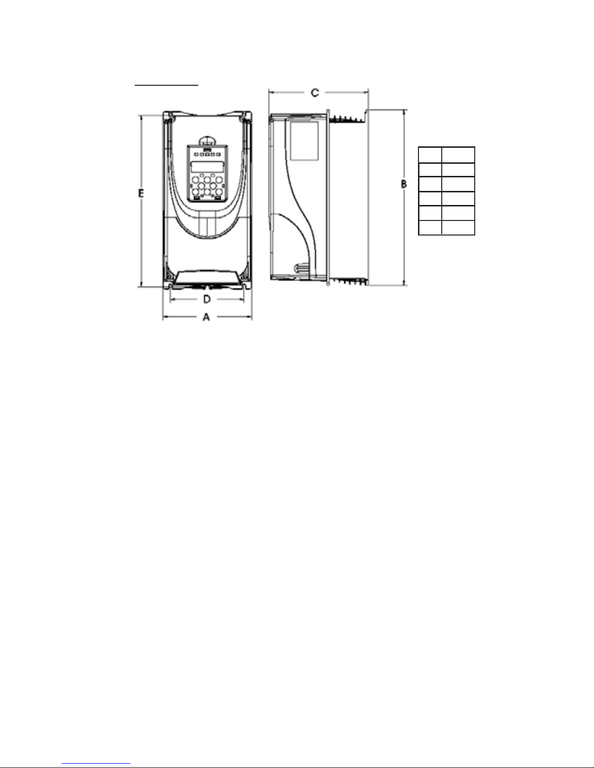
INVERTER 340G FAST START
- Assure that the “RUN” command in the terminal board is disabled.
- Press Mmore than one time until you reach the S.000 menu (net voltage).
- Enter the parameter by the E key, set here the net voltage by up and down keys and chose
among 230, 380, 400, 420, 440, 460, 480 (volt).
- Press Eto confirm and go out. When you come back to the “S.000” writing press . Now you
display “S.001” (net frequency) Press and set here the net frequency by the keys and 50 or
60 Hz, press Eto confirm and go out.
- Now go on according to the sequence by the key and set in the same way the
following parameters:
- S.100 : [V] nominal voltage of the motor (max inverter output voltage).
- S.101 : [Hz] motor nominal frequency
- S.150:[A]motor nominal current.
- S.151: motor poles couples (example: motor 50Hz 2850 rpm S.151=1).
- S.152 : motor power factor (Cosj). If you do not know it leave the standard parameter.
- S.201 : [Hz] max reference sequence. Set the motor nominal frequency to obtain, by the
max speed set point, the correspondent motor nominal speed.
- S.202 : [Hz] frequency reference (speed). Set “1” if you want to use analogical 0-10V input
(examplepotentiometer),“3”ifyouwantuse a constant speedtobeset ontheS203parameter.
- S.203 : [Hz] digital reference frequency (constant speed), set here the output frequency
corresponding to the motor speed you chose.
If you use the potentiometer, or however the analogical input, you should not set this parameter.
- S.300 : acceleration ramp in seconds
- S.301: deceleration ramp in seconds.
- S.400: [%] manual voltage boost in % on the motor nominal voltage.
Once you increase the motor couple at low turns, set a different value from the standard one
only if necessary.
- Note : all parameters which are modified are not saved in a permanent way.
Once you switch the motor off and on the inverter loads the previous parameters, to save the
parameters in a permanent way you should enable the following parameter.
- S.901 : settings saving. Once you enter the display displays “oFF” (C.000) press the key
and ”do” appears, press E , the display should display for a while “DONE”, that is carried out.
End of the procedure
UTILITIES:
- Self calibration of the motor stator resistance:
enable the procedure by the S.900 parameter, carry out the command in the same way of
the par. S.901.
- Automatic boost (increases the motor speed couple at middle – low rate)
you can enable it by the S.401 paragraph : “0” = disabled; “1” = enabled.
- Memorize permanently by the S.901 paragraph.
PARAMETERS TO BE SET FOR THE FUNCTIONING BY MOTO - POTENTIOMETER
-F.050= 5 (reference CH1 on motor - potentiometer)
-I.001 = 23 (digital input 2, programmed as Up key motor - potentiometer)
-I.002 = 24 (digital input 3, programmed as Down Key motor - potentiometer)
Options:
-F.012 = 0/1 (0 = unidirectional motor – potentiometer;
1= bidirectional mono - potentiometer)
- F.013 = 0/1 (0 = the motor - potentiometer sets to zero when you switch off the inverter;
1 = motor – potentiometer with memory)

RowanElettronicaS.r.l. www.rowan.it Tel.+39-0444.905566
pag.11
The commands on the keyboard will become as illustrated:
PARAMETERS TO BE SET FOR A FUNCTIONING SIMILAR TO C330
- F.060 = 1 (analogical input on the 1 multi – frequency channel)
- F.061 = 3 (digital frequency reference F.101 on the 2 multi – frequency channel)
- F.050 = 4 (multi – frequency selected on the n. 1 reference channel)
- I.001 = 19 (digital input 2 programmed as STOP IN RAMP command)
- I.005 = 2 (digital input 6 programmed as RUN INVERSION command )
- P.003 = 0 (when you switch on the inverter, the motor starts by input enabled RUN )
- P.004 = 1 (when you disable the RUN you keep the feeding away to the motor)
- F.101 = input the frequency value of the selected 1 CONSTANT SPEED by digital input
n. 3 (clamp n.3)
F.102=input thefrequencyvalueoftheselected2CONSTANTSPEEDby digitalinput n.4(clamp n4)
-F.103=input thefrequencyvalueoftheselected3CONSTANTSPEEDcombiningthedigital inputsn.3and4
The commands on the keyboard will become as illustrated:
COM-IN Digital inputs
RLA
Programmable
Output
+24V
COM-IN Digital inputs
RUN
STOP IN RAMP
A1 A2 A3 1 2 3 4 5 6 7 8 9 10 11 12
B1 B2 B3 13 14 15 16 17 18 19 20 21 22 23 24
CONSTANTSPEED1
CONSTANTSPEED 2
INVERSION
Potentiometer R
min. 4,7 kOhm
RUN
A1 A2 A3 1 2 3 4 5 6 7 8 9 10 11 12
B1 B2 B3 13 14 15 16 17 18 19 20 21 22 23 24
RLA
Programmable
Output
+24V
UP
DOWN

RowanElettronicaS.r.l. www.rowan.it Tel.+39-0444.905566
pag.12
Table of contents
Other Rowan Elettronica Inverter manuals