Camp Power SIM-700 User manual

ATTENTION:
Please follow the instructions in this user manual and pay close
attention to all warnings. Please DO NOT operate before reading this
USER MANUAL.
USER MANUAL
SIM-700

NOTICES
•Camp Power™products are protected under patent law.
•Camp Power reserves the right to modify or change parts of or all the
specications and pricing policies at company’s sole discretion.
•Camp Power shall not be liable for losses caused by either incidental or
consequential use in connection with the furnishing, use or performance of
this manual as well as any information contained herein.
•This document may not be copied or edited without Camp Power’s prior
written approval.
CONTACT US
If you have any problems or need help when using our products,
please contact Camp Power LLC, your local distributor, or visit
www.CampPower.com • +1.866.476.2586
©2018 Camp Power LLC, All Rights Reserved
Camp Power is a registered trademark of Camp Power, LLC
Publication Number: SIM700-001
The information provided in this documentation contains general descriptions and/
or technical characteristics of the performance of the products contained herein. This
documentation is not intended as a substitute for and is not to be used for determining
suitability or reliability of the products for specic user applications. It is the duty of any such
user or integrator to perform the appropriate and complete risk analysis, evaluation and
testing of the products with respect to the relevant specic application or use thereof. Neither
Camp Power nor any of its afliates or subsidiaries shall be responsible or liable for misuse of
the information contained herein.
i

ii
TABLE OF CONTENTS
1. INTRODUCTION ........................................1
1.1 Foreword ............................................1
1.2 Product Description. . . . . . . . . . . . . . . . . . . . . . . . . . . . . . . . . . . . 1
1.3 Product Diagram ......................................1
1.4 Safety Precautions ....................................2
2. INSTRUCTIONS .........................................2
3. OPERATING INSTRUCTIONS ..............................4
3.1 System Circuit Diagram.................................4
3.2 AC Priority Mode ......................................4
3.3 AC_Gen_Shore Is Cut Off ...............................5
3.4 No AC or Solar Input ...................................5
3.5 PV Solar Priority Mode .................................5
4. PRODUCT PANEL & DISPLAY DETAILS .....................6
5. ON/OFF INSTRUCTIONS .................................7
5.1 AC Priority ...........................................7
5.2 PV Priority Switch .....................................7
5.3 Turning On Steps......................................7
5.4 Turning off steps ......................................8
6. LCD DISPLAY...........................................9
7. SPECIFICATIONS.......................................10
11
1. INTRODUCTION
1.1 Foreword
This manual provides a detailed introduction regarding the use of the
Camp Power SIM-700. Please read the user instructions thoroughly
in order to get the maximum benet from your SIM-700. Should any
questions arise during installation, please contact your installer or customer
support (see page i).
1.2 Product Description
This manual provides detailed instructions for the Camp Power SIM-
700. The SIM-700 is a smart, portable, home and camping, inverter. This
inverter has pure sine wave output, with exceptional compatibility, which
can be connected to refrigerators, electric fans, televisions, uorescent
lamps etc, without damage to devices or batteries. The SIM-700 is safe,
reliable, and easy to use.
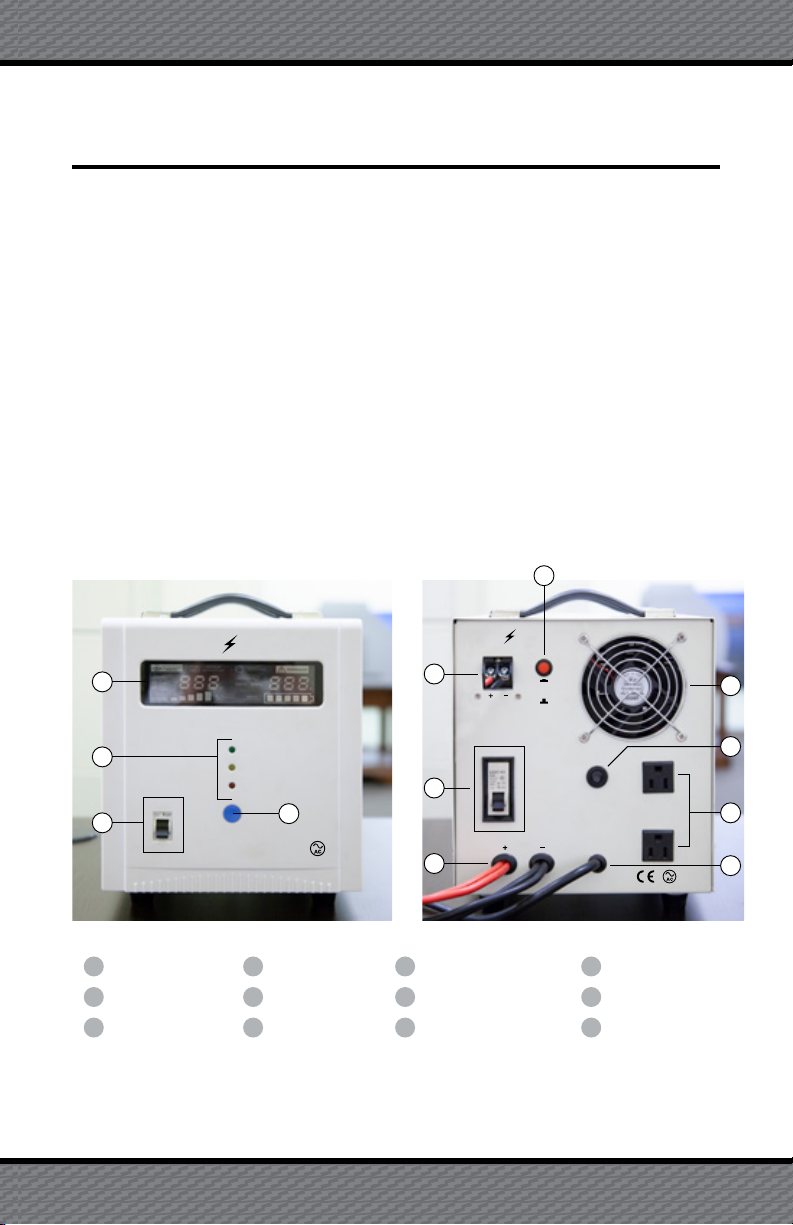
1.3 Product Diagram
SIM-700
SOLAR INVERTER MPPT
SOLAR
BATTERY
FAULT CIRCUIT BREAKER
AC OUTPUT
AC OUTPUT
TOTAL OUTPUT
(700 Watts Max)
15VDC~50VDC
PV
BATTERY IN
12VDC AC POWER IN
PV SOLAR IN
(Battery will charge)
ON/OFF
ON
AC POWER
SWITCH
OFF
PV SOLAR
ON
OFF
CAMP POWER CAMP POWER
PV PRIORITY
(Solar)
AC PRIORITY
(Wall/Generator)
LCD Display 4 ON/OFF 7 Battery 12VDC Cable 10 Circuit Breaker
Indicators 5 PV Solar Input 8 PV/AC Priority Switch 11 AC Outputs
1
2
AC Power Switch 6 PV Solar Switch 9 Cooling Fan 12 AC Power In Cable3
15
6
7
9
11
12
10
8
2
34

2
1.4 Safety Precautions
1. Please read the “Safety Precautions” before use to ensure safe and
proper operation of the SIM-700. Keep this manual in a safe and
secure place. Warranty will be null and void if the user fails to follow
all warnings and cautions in this manual.
2. Please follow all warnings when operating this unit.
3. Keep the inverter away from direct sun, rain, and humid conditions.
4. Keep the inverter away from heat sources like, re, electric heaters,
ovens, furnaces, etc.
5. Keep a safe distance, approximately 4-6 inches, for ventilation and
follow the manual when installing.
6. When cleaning, always turn the power off. Use a clean dry cloth and
do not use liquids to clean this product.
7. In the event of electrical re, use only dry powder re extinguisher.
There is a danger of electric shock if a liquid re extinguisher is used.
8. DO NOT open the case or touch any internal parts or wiring. Only
connect cables to the provided external ports. Warranty is voided if
case is opened.
9. Please contact Camp Power for any maintenance needs. (See page i
for contact information)
2. OPERATING INSTRUCTIONS
2.1 Product Installation & Connection Steps
1. Please open the packaging carton to verify that product is
undamaged due to shipping.
2. ATTENTION: Always connect the battery properly to avoid serious
damage to the unit.

3
3. Always connect the solar panels properly, check the voltage, polarity
of positive and negative carefully;
4. Select the machine working mode; for solar energy systems, select
the PV priority, otherwise AC priority
5. Press the ON/OFF button to start, to ensure it can work normally and
connect the mains.
2.2 Precautions
1. Connect properly to the battery and solar panel, reversed or hight
voltage will cause serious damage.
2. Be connected to ground securely.
3. Don’t install this product outdoors. Placing in or near water may
cause electricution. Always place in a dry location.
4. ATTENTION: Device may become warm to the touch when
in use. Place unit atleast 50cm away from any person during use.
Ensure there is adequate ventilation around unit, and keep away from
ammable materials.
5. If the product malfunctions, disconnect the main input immediately,
and then shut unit down, Disconnect the battery and solar panel
switch, and take note of the failure and note any fault on the LCD
screen. In event of failure please contact your dealer promptly.
6. Disconnect all power inputs and outputs if the unit is hot. The unit has
a high temperature shutdown, if this happens it will give a beeping
sound. Disconnect output loads turn off solar (PV) and let the unit
cool down. After cool unit has cooled down you can restart the unit.
7. If more than 700W of load is connected the unit will give a beeping
warning. If a higher load is connected the unit will shut off.

4
3.2 AC Priority Mode
When AC power supply is normal: AC input will provide power to AC
outputs through regulator. At this time, PV gives power to batteries only
through MPPT control system.
3. OPERATING INSTRUCTIONS
3.1 System Circuit Diagram
3.3 AC_Gen_Shore Is Cut Off
The system automatically acts as a UPS (Universal Power Supply) and
will convert the energy of battery and PV solar promptly, this allows the
constant power to AC output. If PV solar power is not strong enough,
then battery will continue to supply power to outlets until drained.

5
3.4 No AC or Solar Input
The system will convert to the battery to supply load promptly and give
constant power supply.
3.5 PV Solar Priority Mode
1. During the day, with ample sunlight, and AC Switch is non: solar panel
will adjust to the largest state through solar power controller and
give power to load through the inverter (AC input as a standby), and
charge the battery at the same time (see below diagram);

66
2. During the evening (or rainy days, with no sun), and switch is on:
system will provide power through battery rst, discharge until low
voltage protection, and then automatically switch to the AC Input
and provide the power to load through the regulator, and supplement
electricity to battery till the set value (reversed a certain power in case
of emergency situation, but not full charged), nally wait for solar panel
to charger it full.
4. PRODUCT PANEL & DISPLAY DETAILS

7
TOP Green LED: Solar panel connect state. Long light means normal.
Light off or ash means connect unusual
Middle Yellow LED: Battery connect state: long light means normal,
light off or ash means connect unusual
Bottom Red LED: Means abnormal state, light means solar part
abnormal.
5. ON/OFF INSTRUCTIONS
5.1 AC Priority
1. Turn On: When AC Switch is on, inverter will work in AC mode, and
while using AC charging will charge the battery.
2. Turn Off: Hold on/off for 3 seconds to put unit in standby/off mode.
Hold on/off for 3 second to power unit on.
5.2 PV Priority Switch
1. On: PV supplies to battery. AC output usses inverter to power loads.
PV solar is main input surpb.
2. Off: When inverter shut down and cut off the output, it will not switch
to the inverter mode. Note: currently in inverter mode, if AC input is
normal voltage you need cut off the AC switch to shut down; When
AC input voltage is low, it can switch to Mains mode after shut down
and no output.
3. AC charging is main charging for unit. If AC switch is on and battery
voltage is low unit will charge when AC Power is available.
5.3 Turning On Steps
1. Please ensure the battery connecting properly (positive/negative and
voltage parameters consistent with the products identication).
ATTENTION: Do not use unit unless connected to 12V battery.
Table of contents


