Rowan Elettronica 400 Series User manual

G-SERIESG-SERIES
G-SERIESG-SERIES
G-SERIES VECTVECT
VECTVECT
VECTORIAL MOORIAL MO
ORIAL MOORIAL MO
ORIAL MOTT
TT
TORSORS
ORSORS
ORS
INVERINVER
INVERINVER
INVERTER SERIES 400TER SERIES 400
TER SERIES 400TER SERIES 400
TER SERIES 400
Motors, drives, accessories and services for automations
Via Ugo Foscolo, 20 - CALDOGNO - VICENZA - ITALIA
Tel.: 0444-905566 (4 linee r.a.)
Fax: 0444-905593 E-mail:[email protected]
InternetAddress: www.rowan.it
Rev.5
date
20/03/09
MANU.400S.QUICKSTART
WINDER
SERIAL
COMMUNICATION
RS 485RS 485
RS 485RS 485
RS 485
POSITIONER
1234567890123456789012
ELECTRONIC GEAR
MASTER SLAVE
REGULATOR
SET
FDB
REG
+
-
GENERATOR
ACTIVE FRONT END
1
1
1
1
1
1
1
1
1
1
1
1
LIFT
BRAKE
STOP
V/F SCALAR CONTROL
WITH HIGH TORQUE
V
Hz
HTHT
HTHT
HT
CLOSED LOOP
VECTOR CONTROL
FOCFOC
FOCFOC
FOC
FLYCUT
1234567890123456789012
1234567890123456789012
12
12
12
12
12
12
123
1
2
3
1
2
3
1
2
3
1
2
3
123
1234567890

PAGE
2 / 48
Via Ugo Foscolo, 20
36030 - CALDOGNO - VICENZA - ITALY
Rev.5 - 20/03/09
INDEX
Chapter 1: GENERAL WARNINGS BEFORE INSTALLATION ............................................................. pag. 3
- Description of symbols in the manual................................................................................................... pag. 3
- General instructions on safety ............................................................................................................... pag. 3
- Dangerous situations............................................................................................................................. pag. 3
- Responsibility and warranty................................................................................................................... pag. 3
- Compatibility of the manual with the firmware version of the inverter.................................................. pag. 3
Chapter 2: KEYBOARD OPERATING INSTRUCTIONS ........................................................................ pag. 4
- General description ................................................................................................................................ pag. 4
- Display when starting ............................................................................................................................. pag. 4
- Keys function........................................................................................................................................... pag. 4
- Procedure to modify a parameter .......................................................................................................... pag. 4
Chapter 3: QUICK INSTALLATION IN SCALAR MODE........................................................................ pag. 5-7
- Quick installation aims ........................................................................................................................... pag. 5
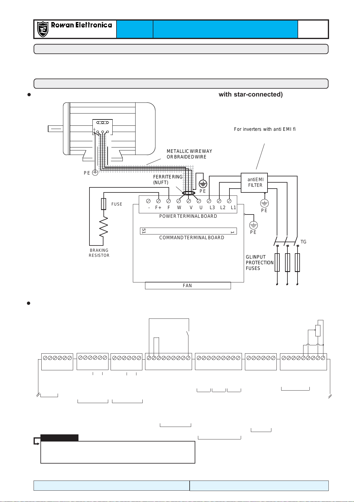
- Connection diagrams............................................................................................................................. pag. 5
-Installation ............................................................................................................................................... pag. 6-7
- Procedure to restore default setups ...................................................................................................... pag. 7
Chapter 4: QUICK INSTALLATION IN VECTORIAL MODE .................................................................. pag. 8-9
- Quick installation aims. .......................................................................................................................... pag. 8
- Connection diagrams . ........................................................................................................................... pag. 8
-Installation ............................................................................................................................................... pag. 9
Chapter 5 : TECHNICAL FEATURES ..................................................................................................... pag. 10-13
- Genaral features of the inverter potentialities ....................................................................................... pag. 10-11
- Electric and power characteristics summary tables for the inverter Series 400 ................................. pag. 12-13
- Inverter derating according to PWM frequency ...................................................................................... pag. 13
Chapter6:MECHANICALINSTALLATION ................................................................................................ pag. 14-15
- Drives dimensions and weights ............................................................................................................ pag. 14
- Suggestions for a correct installation.................................................................................................... pag. 15
Chapter7:ELECTRICALINSTALLATION................................................................................................. .. pag. 16-19
- General warnings before connection of the threephase power supply ............................................... pag. 16
- Wiring system and electromagnetic compatibility ................................................................................ pag. 16
- Table of threephase anti E.M.I. filters and ferrite toroids for different inverters...................................... pag. 17
- Reducing the harmonic distortion .......................................................................................................... pag. 18
- Table of filters reducing the harmonic distortion for different inverters.................................................. pag. 18
- Reducing the dV/dt .................................................................................................................................. pag. 19
- DV/dt reduction filters table for different inverters ................................................................................... pag. 19
- Electrostatic discharges (ESD)............................................................................................................... pag. 19
Chapter 8: BRAKING RESISTORS ......................................................................................................... pag. 20-21
- Table of braking resistors for Rowan inverters..................................................................................... pag. 20
- Dimensions of Rowan braking resistors .............................................................................................. pag. 21
- Mechanical installation and electrical connection ................................................................................ pag. 21
- Inverter setup for dynamic braking ......................................................................................................... pag. 21
Chapter 9: TERMINAL BOARD DESCRIPTION..................................................................................... pag. 22-27
- Power terminal board description ......................................................................................................... pag. 22
- Standard terminal board for signals description .................................................................................. pag. 22-25
- Optional B404S.A card-edge connectors description........................................................................... pag. 26-27
Chapter 10: COMPLETE PARAMETERS LIST WITH STANDARD SETUPS AND DISPLAYS.......... pag. 28-34
Chapter 11: SUMMARY TABLES FOR I/O RESOURCES PARAMETERS.......................................... pag. 35
Chapter 12: INVERTER FAULTS AND ALARMS ................................................................................. pag. 36
Chapter 13: ROWAN G-SERIES VECTORIAL MOTORS...................................................................... pag. 37-41
- Motors general features ......................................................................................................................... pag. 37
- Motors connection description............................................................................................................... pag. 38-39
- Measures of motors with brake ............................................................................................................. pag. 40
- Brakes electromechanical features table ............................................................................................. pag. 41
- Brake connection .................................................................................................................................... pag. 41
- Fan systems and protection levels table for motors and fans ............................................................. pag. 42
- Motors mechanical limits ....................................................................................................................... pag. 42
- Guide to "Motor/Inverter pairing off" tables............................................................................................. pag. 43
- Motor/Inverter pairing off table (1500 rpm - 380/460Vac)...................................................................... pag. 44
- Motor/Inverter pairing off table (3000 rpm - 380/460Vac)...................................................................... pag. 45
Chapter 14: INFORMATION ON MANUALS .......................................................................................... pag. 46

PAGE
3 / 48
Via Ugo Foscolo, 20
36030 - CALDOGNO - VICENZA - ITALY
Rev.5 - 20/03/09
Description of symbols in the manual
It means that the following subject is very important and must be read carefully
It means that the following subject is linked to a generic danger for safety.
It means that the following subject shows the presence of a dangeruos voltage. It indicates that
high voltage may cause dangerous accidents or death.
- Before installation, connection or any operation on the inverter or on the motor, read this manual carefully, in order to
perform correct operations and to pay attention to safety rules.
Any use of the Rowan inverters and motors which may differ from what is written on this manual is strictly forbidden.
- This instruction manual is addressed to skilled personnel, who is acquainted with installation and use norms in
accordance with safety and protection standards. Both the motor and the inverter when connected may be dangerous for
things and people. The user is responsible for a correct installation, which must be in accordance with the directives in
force.
- The inverter belongs to the restricted sales distribution class in compliance with EN61800-3 standard. In a domestic
environment this product may cause radio interferences, in which case the user may be required to take adequate safety
measures.
- The inverter, the possible external filter and the motor must be earthed permanently and properly and must be protected
from the supply voltage in accordance with the directives in force.
- The max. inverter protection is obtained by B differentials, preferably 300mA-type. Internal or external anti E.M.I. filters
leakage current is <18mA; Please remind that the EN50178 directive says that, in case of leakage current >3,5mA, the
earth wire must be steady and doubled.
- When the inverter cover needs to be removed, as e.g. for DIP switches setting or for maintenance, it is compulsory to
wait for at least 5 minutes after inverter quenching for the internal capacitors to discharge. Internal components
and terminals subject to dangerous voltages (L1, L2, L3, U, V, W, F, F+, -) can be touched only in absence of power
supply and when the power supply between F+ and – terminals is <50Vdc. Please remind that most internal
components are sensitive to ESDs, so limit yourself to set DIP switches without touching any other component.
- ROWAN ELETTRONICA s.r.l. declines any responsibility for any inaccurancies contained in this manual, due to printing and/or
transcription mistakes. It reserves the right to make any variations that it considers necessary for better functioning of the product,
without prior notification.
- Regarding the data and characteristics mentioned in the manual, a max. 10% tolerance has been allowed, if not otherwise
indicated. Diagrams are mere examples and should be perfected by the customer.
- The product warranty is considered ex-works and is valid 12 months from the date of leaving ROWAN ELETTRONICA s.r.l. premises,
according to the conditions written on the specific document to be asked ROWAN Sales Department.
Compatibility of the manual with the firmware inverter version
See manual code MANU.400S.QUICKSTART.
To gather information about the active applications of your inverter, please go to Chapter 18 “DRIVERS CODING”.
Caution!
GENERAL WARNINGS BEFORE
INSTALLATION
Chapter 1
GENERAL WARNINGS BEFORE INSTALLATION
Caution!
Dangerous situations
In peculiar setup conditions of the inverter, after power losses, the motor might start automatically. The motor rotation
manual controls which can be set by the keyboard must be used with great attention, in order to prevent
mechanical damages and accidents against people. Setup errors might cause unintentional starts. At first start, in
case of faults on the inverter or of lack of power supply, it may not be possible to control the motor speed and the
direction. The rate contact can’t be held as valid for a safety stop; in some setup conditions or of inverter faults, its
disabling may not be followed by a prompt stop of the motor. Only the inverter electromechanical disconnection from the
power supply excludes any action on the motor.
The installation of the inverter in areas at risk, in presence of inflammable substances, combustible vapours and dusts
may cause fires and explosions; the inverters must be installed far from this kind of areas.
Avoid the penetration of water or any liquids into the machine in any case.
Do not perform dielectric rigidity tests on the drive parts.
Responsibility and warranty
When using the device or the internal cards take care on avoiding the generation of electrostatic
discharges (ESD) that may cause irreparable damages to some of the components.

PAGE
4 / 48
Via Ugo Foscolo, 20
36030 - CALDOGNO - VICENZA - ITALY
Rev.5 - 20/03/09
The keyboard enables to change operation parameters (saved in eeprom) and to visualise useful data during the working
phases such as: speed reference, motor reference and frequency, motor current, line voltage and last fault occurrence.
Thanks to serial connection, the keyboard can be distanced from the panel of a control panel by a max. 25m distance.
ROWAN ELETTRONICA s.r.l. supplies on request the keyboard distancing cable.
The keyboard is made up of:
- an alphanumeric LED display, 2x16 characters, backlit
- four mechanical keys that give the feel of the key that has been pressed
- two signalling LEDs, one for run (RUN) and one block for fault (FAULT)
ESCAPE key enables to return to the menu or to the higher level
PROGRAM key enables to enter the submenus, to modify parameters and to save
UP key enables to scroll the displayed variables ONWARDS and to set the numerical variables in the parameters
modification towards positive values
DOWN key enables to scroll the displayed variables BACKWARDS and to set the numerical variables in the
parameters modification backwards to negative values
To speed up the setup of parameters with high values, follow the instructions below:
When you are increasing a value (meant without comma) by pressing UP key, if after 4/5 sec. you press DOWN key once,
hundreds and successively thousands will be modified and so on.
To go back to normal speed with units and tens frequency, press UP key again.
In the same way, if you are decreasing the value by DOWN key, UP key will speed up setup.
- Press the P key, so par. 1.1.1 LINE VOLTAGE will be displayed.
- Press UP key to selec par.1.1.2 MOTOR NOM CURRENT.
- Press P key; the display area for the numerical value to be set will start flashing to signal that it is now possible to
modify its value by UP and DOWN keys.
- Press UP key to increase the value and DOWN key to decrease it.
To confirm the value setup, press P key; to exit without any modifications press ESCAPE key; in both cases the number
will stop flashing.
ESCAPE key always enables to exit from the programming and to return to higher menus to DISPLAY STATUS. The
parameters modifying procedure by string selection is alike and in that case UP and DOWN keys will select the available
strings in the menu instead of numerical values.
The machine starts in DISPLAY MENU and shows one among the 10 default variables from the 2.1 DISPLAY VARIABLE
menu. Use UP and DOWN keys to scroll variables. The last variable selected is displayed when starting. See Chapter
10: PARAMETERS AND VISUALISATIONS, on paragraph “DISPLAY STATUS description” to change the default variables
displayed.
Display when starting
KEYBOARD OPERATING INSTRUCTIONS
Chapter 2
The keyboard doesn’t contain any parameter buffer (see Chapter 11 PARAMETERS TRANSFER).
Caution!
Keyboard general description
Keys function
Procedure to modify a parameter
RUN: LED signalling drive
running and operational
Display area for the description of the
selected menu/parameters/variables
Display area for the string or
numerical value of the selected
parameter or variable
Display area for the order
number of the selected
menu/parameters/variables
Note: if the code is too long,
only last part is shown
Mechanical keys for setup RUN
FAULT
E
P
MOTOR NOM CURREN
1.1.2 10.0A
FAULT: Light with two functions:
Flashing=ALARM
Fixed = INVERTER BLOCK
See Chapter 17 “INVERTER FAULTS
AND ALARMS” to know the reason for
the alarm or for the inverter block.
P
E

PAGE
5 / 48
Via Ugo Foscolo, 20
36030 - CALDOGNO - VICENZA - ITALY
Rev.5 - 20/03/09
The aim of this paragraph is to teach the user, quickly and correctly, speed setup by a potentiometer of a normal
asynchronous motor in V/F (Voltage/Frequency) scalar mode.
Connection diagram of the command terminal board
SERIAL
RS485
AO0 - MOTOR CURRENT%
+24VDC
0VDC
COM-I
I6
I5
I4
I3
I2
I1
0VDC
AO3 - NO FUNCTION
AO2 - MOTORSPEED%
AO1 - MOTOR SPEED %
0VDC
NO- O3
COM- O3
NC- O3
NO- O2
COM- O2
NC- O2
NO- O1
COM- O1
NC- O1
AI4
AI3
AI2-
AI2+
AI1-
AI1+
-10VDC
+10VDC
0VDC
1
2
3
4
5
6
7
8
9
16
17
18
19
20
21
22
23
24
25
26
27
28
29
30
31
32
33
46
47
48
49
50
51
10
11
12
13
14
15
B
A
0VDC-SER
0VDC
+15VDC
+12VDC-EN
0VDC-EN
B
B
A
34
35
36
37
38
39
A
+12VDC-EN
0VDC-EN
B
B
A
40
41
42
43
44
45
A
+5VDC
POTENTIOMETER
FORSPEED
SETUP
ANALOG
OUTPUTS
ANALOG
INPUTS
RELAIS OUTPUTS
DIGITAL INPUTS
ENCODER 2 ENCODER 1
FAULT RELAY
RATE RELAY
- RUN
- STOP IN RAMP
- FIXED SPEEDS
- DEC1 FIXED RAMP
- FIXED SPEEDS
- ACC1 FIXED RAMP
SPEEDTHRESHOLD
RELAY
10K
RATE
Analog/digital inputs and outputs can be programmed freely.
The functions shown in this diagrams concern standard
programming in SCALAR MODE.
Caution!
Chapter 3 QUICK INSTALLATION IN
SCALAR MODE
THREEPHASEPOWERSUPPLY50/60HZ
12345
1
234
5
1
234
5
1
234
5
1
234
5
1
234
5
1
234
5
1
234
5
12345
123456789012345678901234567890121234567890
1
2345678901234567890123456789012123456789
0
1
2345678901234567890123456789012123456789
0
1
2345678901234567890123456789012123456789
0
123456789012345678901234567890121234567890
METALLICWIREWAY
ORBRAIDEDWIRE
PE
51
1
COMMANDTERMINALBOARD
POWERTERMINALBOARD
- F+ F W V U L3 L2 L1
antiEMI
FILTER
TG
GLINPUT
PROTECTION
FUSES
FAN
FUSE
BRAKING
RESISTOR
1234
1
23
4
1
23
4
1
23
4
1
23
4
1
23
4
1
23
4
1
23
4
1
23
4
1
23
4
1
23
4
1
23
4
1
23
4
1
23
4
1234
PE
PE
PE
FERRITERING
(NUFT)
For inverters with anti EMI filter
included, remove the external filter or
use it to come under B class, if
necessary
Connection diagrams for scalar mode
Quick installation aims
Connection diagram of the power terminal board (example with star-connected)

PAGE
6 / 48
Via Ugo Foscolo, 20
36030 - CALDOGNO - VICENZA - ITALY
Rev.5 - 20/03/09
MAX MOTOR SPEED
1.3.1 1500.rpm Set the motor max. speed
Setup range: from 0 rpm to 30000 rpm
Read carefully Chapter 1: GENERAL WARNINGS BEFORE INSTALLATION before installing.
See Chapter 6: MECHANICAL INSTALLATION for the inverter positioning.
See Chapter 7: ELECTRICAL INSTALLATION for connecting the inverter and for E.M.C. directives.
See Chapter 8: BRAKING RESISTORS for connection, if neccessary.
Connect the inverter with ref. to the Scalar connection diagrams on the previous page.
See Chapter 2: KEYBOARD OPERATING INSTRUCTIONS
This parameter enables to select the following motor control modes:
V/F = Scalar mode
VECT_ENC = Vectorial mode with encoder ring closure
Leave the default setting: V/F
Press UP key to select the parameter
Press ESCAPE key to return to DISPLAY STATUS
Press PROGRAM key to modify the following parameters from the BASIC DATA menu:
MOTOR NOM CURREN
1.1.2 10.0A Set the nominal current of the motor which is connected to the inverter.
Setup range: from 0.0A to a standard parameter value.
MOTOR NOM FREQUE
1.1.3 50.0Hz
Set the nominal voltage of the motor (nominal voltage to frequency).See the values on the
motor plate according to the type of connection (star network or delta connection)
Setup range from 1.V to 2000.V
Set the nr of motor poles
See the value on the motor plate. Setup range: 2_POLES, 4_POLES, 6_POLES, 8_POLES
RAMP ACCEL. TIME
1.2.1 10.00s Set the motor acceleration ramp
Setup range: from 0.01s to 600.00s
RAMP DECEL. TIME
1.2.2 10.00s Set the motor deceleration ramp.
Setup range: from 0.01s to 600.00s
Press ESCAPE key until parameter MOT CONTROL TYPE is displayed:
- Supply power to the inverter and check the correct setting of the potentiometer as follows:
-SelecttheSPEED REFERENCE variablebyUPandDOWNkeys.
- Select the potentiometer at its idle and peak rate and check the setting between 0 up to 1500 rpm in SPEED REFERENCE.
- Idle the potentiometer and set SPEED REFERENCE at 0 rpm..
MOT CONTROL TYPE
100.1 V/F
APPLICATION
100.5 SPEED
This parameter enables to select the application concerning the motor function in the final
system. Leave the default setting: SPEED (Motor controlled at rate)
MOTOR POLES
1.1.5 4_POLES
MOTOR NOM VOLTAG
1.1.4 400.V
QUICK INSTALLATION IN
SCALAR MODE
Chapter 3
LINE VOLTAGE
1.1.1 400.V Set the inverter supply voltage to the L1, L2, L3 terminals.
Choose the voltage which is the closest to the supply voltage true value. Setup range from
150.V to 600.V
Start programming by RATE contact off. The rate contact cannot be held as valid in case of safety stop, since in case of
particular programming conditions or of inverter fault, its disconnection might not determine the sudden motor stop.
For safery reasons, it is better to be close to the emergency button to block supply to the TG contactor coil supplying the
inverter.
The storage of the inverter for longer than 2 years could damage the DC link capacitors, which shoud be restored: in
order to do that, it is suggested to supply power to the inverter in OFF rate for at least 2 hours.
Installation in scalar mode
Set the nominal frequency of the motor (frequency to nominal voltage). See the value on
the motor plate. Setup range from 1.0 Hz to 800.0 Hz

PAGE
7 / 48
Via Ugo Foscolo, 20
36030 - CALDOGNO - VICENZA - ITALY
Rev.5 - 20/03/09
MIN MOTOR SPEED
1.3.2 0.rpm Set the motor min. speed
Setup range: from 0 rpm to par. 1.3.1 MAX MOTOR SPEED
FIXED BOOST
1.5.1 1.0%
Boost voltage must not cause an absorption rate which is higher than the motor nominal current. For the first test, set
1.0% as default value
Set the motor speed for the first rotation test, which will be performed later by the
manual commands of the keyboard.
Setyp range: from 0 rpm to par. 1.3.1 MAX MOTOR SPEED.
Set to 500rpm.
On this parameter, the motor rotation test is enabled by UP and DOWN keys
UP=DX DOWN=SX
SPEED 0.rpm
Press the UP key; the following will be displayed: BASIC DATA OK
E=ESC P=CONTINUE
The screen indicates that the setup of the basic parameters to activate the open ring control is over and that we can exit
the programming by pressing ESCAPE key. This way you go back to DISPLAY STATUS. Later on, if further functions
differring from the aim of the quick installation are necessary, you can scroll the complete menu of the available
parameters by PROGRAM key.
Set the fixed boost voltage on the motor, active from 0.0Hz to 20.0Hz
Setup range: from 0.0% to 25.0%
TEST MANU SPEED
1.4.1 300.rpm
JOG TEST MANU
1.4.2 NO
Select YES to enter the test; the following screen will be displayed:
Perform the rotation test by UP and DOWN pointers:
- Close the rate contact by switching RUN light on.
- Press UP and DOWN pointers to drive the motor on both rotation directions.
SPEED will display the motor speed, which must correspond with the value set in par. 1.4.1.
Press ESCAPE to end the rotation test by the keyboard; the display will show par. 1.4.2
- Perform the rotation test setting the speed by the potentiometer:
- Press ESCAPE key and select MOTOR SPEED variable by UP and DOWN keys.
- Set the potentiometer and verify the motor rotates at the displayed speed.
- Select the MOTOR CURRENT variable and verify the correct absorption by the motor.
- Invert the two phases of the motor (e.g. U and V) to change the rotation direction. By 3.1.1.3 REVERSE SPEED, it is
possible to program a command to invert the rotation direction.
- Go on following the instructions on Chapter 4: QUICK INSTALLATION IN VECTORIAL MODE, if this kind of function in
necessary. Otherwise the basic installation has come to its end.
It is possible to restore all setups and return to standard ones by following the instruction below:
- Disable the rate (RUN light OFF)
- Keep ESCAPE key pressed until 100.1 MOTOR CONTROL TYPE parameter is displayed
- Press UP key to select 100.6 SETUP menu
Press PROGRAM key to select the parameter:
RESTORE SETUP
100.6.1 DEFAULT Check DEFAULT is selected
Press UP key to select the parameter:
ENABLE RESTORE
100.6.2 NO Select YES and confirm by PROGRAM key; YES will be displayed until all default setups are
restored. Then NO will be displayed.
After this kind of operation all customized setups are reset definitively.
Caution!
QUICK INSTALLATION IN
SCALAR MODE
Chapter 3
Caution!
It is possible to check the I/O status by the following variables from the menu 2.1 GENERAL VARIABLE:
2.1.20 DIG. INPUT I1..8 and DIG. INPUT I9..14 as for digital inputs
2.1.22 DIG . OUTPUT O1..8 as for digital outputs
Caution!
Procedure to restore default setup

PAGE
8 / 48
Via Ugo Foscolo, 20
36030 - CALDOGNO - VICENZA - ITALY
Rev.5 - 20/03/09
12345678
1
234567
8
1
234567
8
1
234567
8
1
234567
8
1
234567
8
1
234567
8
12345678
QUICK INSTALLATION AIMS
The aim of this paragraph is to teach the user, quickly and correctly, speed setup by a potentiometer of a Rowan
asynchronous threephase motor in vectorial control with ring closure encoder according to the FIELD ORIENTATION
mode.
Vectorial control connection diagrams
Connection diagram of the power terminal (example with star-connected motor)
AO0 - MOTOR CURRENT%
+24VDC
0VDC
COM-I
I6
I5
I4
I3
I2
I1
0VDC
AO3 - MOTORTORQUE%
AO2 - MOTOR SPEED %
AO1 - MOTOR SPEED %
0VDC
NO- O3
COM- O3
NC- O3
NO- O2
COM- O2
NC- O2
NO- O1
COM- O1
NC- O1
AI4
AI3
AI2-
AI2+
AI1-
AI1+
-10VDC
+10VDC
0VDC
1
2
3
4
5
6
7
8
9
16
17
18
19
20
21
22
23
24
25
26
27
28
29
30
31
32
33
46
47
48
49
50
51
10
11
12
13
14
15
B
A
0VDC-SER
0VDC
+15VDC
+12VDC-EN
0VDC-EN
B
B
A
34
35
36
37
38
39
A
+12VDC-EN
0VDC-EN
B
B
A
40
41
42
43
44
45
A
+5VDC
POTENTIOMETER
FORSPEED
SETUP
ANALOG
OUTPUTS
ANALOG
INPUTS
RELAIS OUTPUTS
DIGITAL INPUTS
ENCODER 2 ENCODER 1
FAULT RELAY
RATE RELAY
- RUN
- STOP IN RAMP
- FIXED SPEEDS
-DEC1 FIXED RAMP
- FIXED SPEEDS
-ACC1 FIXED RAMP
SPEEDTHRESHOLD
RELAY
10K
MARCIA
CONNECTOR
ENCODER
LINE DRIVER
6-WIRESSHIELDED-
CONDUCTOR
CABLE
SERIAL
RS485
Analog/digital inputs and outputs can be
programmed freely. The functions shown in
this diagrams concern standard programming
inVECTORIALMODE.
Chapter 4 QUICK INSTALLATION IN
VECTORIAL MODE
(A)
(B) (G) (E)
(C) (D)
3
12
4
6
5
7
(F)
Connection diagram of the command
terminal board
1
2
3
4
5
6
12345
1
234
5
1
234
5
1
234
5
1
234
5
1
234
5
1
234
5
1
234
5
1
234
5
12345
123456789012345678901234567890121234567890
1
2345678901234567890123456789012123456789
0
1
2345678901234567890123456789012123456789
0
123456789012345678901234567890121234567890
Metallicwireway
or braided wire
PE HEATPROBE
FAN (220Vac)
51
1
COMMANDTERMINALBOARD
POWERTERMINALBOARD
- F+ F W V U L3 L2 L1
antiEMI
FILTER
TG
GL input
protection fuse
50/60Hzthreephase
power supply
FAN
FUSE
BRAKING
RESISTOR
1234
1
23
4
1
23
4
1
23
4
1
23
4
1
23
4
1
23
4
1
23
4
1
23
4
1
23
4
1
23
4
1
23
4
1
23
4
1
23
4
1
23
4
1
23
4
1234
PE
PE
PE
ENCODERCONNECTOR-
LINEDRIVER
FERRITE
RING
(NUFT)
ForinverterswithantiEMIfilterincluded,removethe
externalfilteroruseittocomeunderBclass,if
necessary.
Caution!

PAGE
9 / 48
Via Ugo Foscolo, 20
36030 - CALDOGNO - VICENZA - ITALY
Rev.5 - 20/03/09
Installation in vectorial mode
Connect the inverter with ref. to the Vectorial connection diagrams on the previous page.
Before installation, check the torque characteristics table regarding the possible match between G-Series Rowan
motor and the inverter in hand. In order to do so, it is important to have a look at par. Guide to “Motor/Inverter pairing
off” tables in Chapter 19: G-SERIES ROWAN MOTORS.
The tables sum up parameters setups to perform to operate the machine
- Disable the rate (RUN light off)
- Press ESCAPE key until 100.1 MOT CONTROL TYPE parameter is displayed.
-Press PROGRAMkey andset VECT_ENC fuctionin par.100.1 MOT CONTROL TYPE.
- Press ECSAPE key to return to DISPLAY STATUS.
- Press PROGRAM key to modify the following parameters from BASIC DATA menu:
- Set the encoder pulse nr per rotation in par.1.6.1 E1 ENCODER LINES. See the values on the plate of the motor encoder.
The following parameters can be got out of Chapter 19: G-SERIES ROWAN MOTORS- “Motor/Inverter pairing off” table.
As for motors which haven’t been manufactured by Rowan, see Chapter 16, par. “STANDARD ASYNCHRONOUS
MOTORSINVECTORIALMODE”.
- In par. 1.6.2 KG GAIN, set the speed regulator proportional gain.
- In par. 1.6.3 KI GAIN, set the speed regulator integral gain.
- In par. 1.6.4 VECT MAGNET CURR, set the motor magnetizing current in % ratio to nominal current.
- In par. 1.6.5 ROToR CONSTANT, set the motor rotor constant in Hz.
- In par. 1.10.1 MAX TORQUE, set the max. torque value in % ratio to nominal torque.
- In par. 1.10.15 ADAPT PERC TORQ, set the torque displays/setups adaptation value in %.
- In par. 1.10.16 ADAPT TORQ (Nm), set the torque displays/setups adaptation value in nr.
- In the end in par. 1.12.1 PWM FREQUENCY, set the value 5.00Hz, optimum PWM frequency for vectorial control.
For high power motors, in case of no particular needs for uniformity in rotation, a 3KHz- PWM frequency enables a lower
heating up of the power modules and a better exploitation of the inverter.
For PWM frequencies higher than 5KHz, for noise reasons, keep in mind that you need to derate the inverter following the
rule in Chapter 5: TECHNICAL FEATURES.
- Press ESCAPE key more than once to return to DISPLAY STATUS.
- Start with the potentiometer set so that the speed in SPEED REFERENCE is 0 rpm.
- Enable the rate (RUN light on) and check the correct sped adjustment on the potentiometer, by verifying the display of
thefollowingvariables: SPEED REFERENCE,MOTOR SPEED andENCODER SPEED. All variablesmustdisplay the same
speed rate and the same sign.
- Select MOTOR CURRENT variable and check the motor absorbption is correct if considered the present load conditions.
SPEED REFERENCE
0.rpm ENCODER SPEED
0.rpm
Check the display in ENCODER SPEED variable; on this variable a different speed from that displayed in SPEED
REFERENCE may be visualized, but this must be of the same sign:
- if the speed sign in ENCODER SPEED is opposite to that in SPEED REFERENCE, invert the A and A- encoder channels
connected to 34-35 terminals.
QUICK INSTALLATION IN
VECTORIAL MODE
Chapter 4
While performing the final rotation test to verify the speed setup
by the potentiometer, check the following variables as well, by
selecting them by UP and DOWN keys.
Caution!
FollowChapter 3: QUICK INSTALLATION IN SCALAR MODE, bygetting outof the“Motor/Inverter pairing off” tableson
Chapter 19 the common setup of the following parameters: 1.1.2 MOTOR NOM CURREN, 1.1.3 MOTOR NOM FREQUE,
1.1.4 MOTOR NOM VOLTAGE, 1.1.5 MOTOR POLES. As for motors which haven’t been manufactured by Rowan, get the
information from the motor plate.
Adjust the potentiometer, so that SPEED REFERENCE displays the max. speed.
Default speed adjustment through AI1 analog input is monodirectional; if you need it to be bidirectional, set par. 4.3.1.3
TYPE INPUT = -10V/+10V
Caution!
End of quick installation.

PAGE
10 / 48
Via Ugo Foscolo, 20
36030 - CALDOGNO - VICENZA - ITALY
Rev.5 - 20/03/09
Inverter supply voltage to L1, L2, L3 terminals
Threephase voltage supply................ from 180VAC to 270VAC (standard power supply 220/240VAC)
............................................................ from 320VAC to 460VAC (standard power supplies 380/440/415 VAC)
............................................................ from 320VAC to 490VAC (standard power supply 380/460VAC) just for
............................................................ models from 400/P to 400/2
............................................................ from 380VAC to 506VAC (standard power supplies 440/460VAC)
............................................................ from 560VAC to 760VAC (standard power supply 690VAC) just from 400/5
U V W motor output
Types of motor.................................... retaining asynchronous threephase, Rowan G-Series vectorial
Motor control ....................................... V/FSCALAR
............................................................ FIELDORIENTED VECTORIAL,FEEDBACKED BY ENCODER
Output voltage..................................... from 0 to 100% of the voltage supply
Output frequency ................................ 0HZ800Hz
Wavetype............................................ sine wave
Wave type reconstitution .................... PWM (Pulse With Modulation)
PWMfrequency ................................... To be set from 0.50KHz to 20.00KHz
Overload capacity ............................... 110% of the inverter nominal current in non-stop service
............................................................ 130% of the inverter nominal current for 300sec
............................................................ 175% of the inverter nominal current for 30 sec
............................................................ 250% of the inverter nominal current for 3 sec
Regenerative braking control
With braking module .......................... included in all inverters 400-Series
Regenerated energy dissipation system external resistance connected to F+ and F clips
Digital inputs
Nr of digital inputs .............................. 6 as standard (I1..I6) + 8 by 404S optional card (I7..I14)
Input insulation ................................... optoinsulated in case of external feeding
Connection logic ................................ NPN or PNP
Activationvoltage ................................ 15Vdc min., 30Vdc max.
Programming ..................................... I1 input with fixed rate function. The remaining completely programmable
Input resistance.................................. about 3,6Kohm
Enabling/disabling times ................... 10ms, 20ms with pulse control
Pulse digital inputs
Encoder nr. ......................................... 2 as standard + 1 by 404S optional card
Encoder 0 inputs nr ............................ 2 by 404S optional card
Input insulation ................................... optoinsulated
Connection logic ................................ encoder line driver_push/pull output
Encoders voltage supply .................... 12Vdc, short circuit protected (5Vdc on request)
Max.frequency .................................... 125Khz
Encoder single channel current load. 9,6mA/12Vdc - 8mA/5Vdc
Logic state 1 voltage (12Vdc encoder) more than 6Vdc
Logic state 1 voltage (5Vdc encoder). more than 2,3Vdc
Relay outputs
Relay nr............................................... 3 (O1, O2, O3)
Programming ..................................... completely programmable
Contact nr per relay ............................ one NO/NC exchange
Contact current-carrying capacity ...... 0.5A 120Vac- 1A 24Vac
Digital outputs
Output nr ............................................. 5 (O4, O5, O6, O7, O8) just by 404S optional card
Output insulation ................................ optoinsulated in case of external feeding
Connection logic ................................ NPN or PNP
Programming ..................................... completely programmable
Job voltage supply.............................. max. 100Vdc
Max.current......................................... 80mA
Enabling/disabling times ................... 12ms
TECHNICAL FEATURES
Chapter 5

PAGE
11 / 48
Via Ugo Foscolo, 20
36030 - CALDOGNO - VICENZA - ITALY
Rev.5 - 20/03/09
Analog inputs
A/1 ....................................................... differential +/-10Vdc...12bit (14 bit on request)...sampling time 1ms
A/2 ....................................................... differential +/-10Vdc, 4-20mA, 0-20mA...12 bit...sampling time 5ms
A/3,A/4 ................................................ +/-10Vdc...12bit...sampling time 5ms
A/5 (just by 404S optional card) ......... +/-10Vdc...10bit...sampling time 16ms
A/6, A/7, A/8, A79 (just by 404S optional card) 0/+10Vdc...10bit...sampling time 16ms
Programming ..................................... completely programmable
Analog outputs
AO0 ..................................................... 12bit...updating time from 2,6ms (jst for FAST variables) to 6,6ms
AO1 ..................................................... 12bit...updating time 6,6ms
AO2,AO3 ............................................ 8bit...updating time 20 ms
Output supply voltage ......................... +/-10Vdc
Output current ..................................... max. 10mA
Programming ..................................... completely programmable
RS485 serial connection
Standard records................................ MODBUSRTU...ROWAN
Baudrate ............................................. 1200..2400..4800..9600..19200..38400..57600..76800..115200
Insulation............................................ .optoinsulated
Available voltage supply
+10Vdc, -10Vdc (for potentiometers) . .max. 10mA
+24Vdc (for inputs or other devices) .. short circuit protected...max.250mA
+12Vdc (standard for encoders or sensors).....optoinsulated...short circuit protected...max.200mA
+5Vdc (on request for encoders or sensors).....optoinsulated...short circuit protected...max.500mA
+5Vdc .................................................. short circuit protected...max.200mA
15Vdc .................................................. short circuit protected...max.200mA
Protections
Inverter ................................................ Fault for thermal/electronic protection (I x I x t) on overloading on U, V, W clips
............................................................ Fault for protection on max. peak current U, V, W
............................................................ Fault for programmable time-threshold protection on output current on U, V, W clips
............................................................ Fault for short circuit among U, V, W phases and between the phases and ground
............................................................ Fault for BUSDC overvoltage
............................................................ Fault for overheating of IGBT modules
............................................................ Alarm without fault for BUSDC capacitors end
............................................................ Fault for short circuit on F and F+ terminals for braking resisitor connection
Motor ................................................... Fault for thermal/electronic protection (I x I x t) on overloading
............................................................ Fault for overspeed
Braking resistor .................................. Fault for threshold thermal/electronic protection on prolonged overloading
Special applications
............................................................ ELECTRIC SHAFT (Code 400A)
............................................................ POSITIONER (Code 400A)
............................................................ ADJUSTER (Code 400A)
............................................................ Motor with brake in LIFTING systems (LIFT function, in all versions)
Environmental characteristics
Working temperature.......................... from -5°C to +40°C
Heatsink temperature ........................ rom -5°C to +70°C
Storage temperature .......................... from -25°C to +70°C
Altitude ................................................ max. 1000mt a.s.l. (over this the load must be reduced by 1% every 100mt)
Protection level ................................... IP20
Relative humidit.................................. from 5% to 95% without condensation
Law conformity and electromagnetic compatibility
The 400-Series drivers have been designed to operate in an industrial environment. They are EC products in compliance
with the EMC 89/336/EEC directive with reference to the CEI EN 61800-3 product standard, if connected following the
wiring system in Chapter 7: "ELECTRICAL INSTALLATION" in this manual.
As for the models without internal filter, they are in compliance with the EMC directive only if connected to the relevant
filtering devices supplied separately (see the "Table of threephase anti E.M.I. filters and ferrite toroids for different
inverters" in Chapter 7: "ELECTRICAL INSTALLATION").
Moreover, the drives conform to B.T. 73/23/EEC directive, with reference to EN 60439-1 and CEI EN 60204-1 standards.
Caution! This product belongs to the restricted sales distribution class in compliance with EN61800-3 standard. In a
domestic environment this product may cause radio interferences, in which case the user may be required to take
adequate safety measures.
Chapter 5 TECHNICAL FEATURES

PAGE
12 / 48
Via Ugo Foscolo, 20
36030 - CALDOGNO - VICENZA - ITALY
Rev.5 - 20/03/09
sezisrewoP004.VNI P/ R/ 0/ 1/ L/ 2/ 3/ 4/ 5/ 6/
TCERID.XAM
SREWOP
NIELBACILPPA
STUPTUOW-V-U
ENIL
caV032
.wProtoM
*
WK 36,0 3,1 7,1 5,3 5,4 5,6 01 5,41 5,81 22
.wProtoM
*
AVK.xam 2,18,17,27,467,831028,326,82
ENIL
caV004
.wProtoM
*
WK 1,1 52,2 3 6 5,7 11 5,81 52 03 73
.wProtoM
*
AVK.xam 23 8,48015152431405
NITNERRUC.XAMTCERID
STUPNI3L-2L-1L A 52,2 57,3 2,5 2,9 5,11 5,71 92 04 84 85
NITNERRUC.XAMTCERID
STUPTUOW-V-U A0,35721512253050627
TNERRUCKCOLBDRAC.XAM
STUPTUOW,V,UNI A 5,8 31 02 43 24 26 89 041 071 002
TUPNILG3L-2L-1L
SESUFNOITCETORP A460161025204360808
TNERRUCGNIKARBTCERID
TUPTUO+FF A 7,3 5 7 9 61 61 03 54 54 07
+FFTNERRUCGNIKARB.XAM
%07ELCYCYTUDTUPTUO A 5,5 5,7 11 21 02 52 83 05 05 57
GNIKARB.XIM
+FFROTSISER
TUPTUO
ENIL
caV032
MHO0706040402020101015
ENIL
caV004
MHO0410010707040302515101
REWOPDETAPISSID.XAM
)MWPzHK2HTIWREDLOH( WK50,01,02,03,04,05,06,08,00,12,1
NAFGNILOOC ON ON ON SEY SEY SEY SEY SEY SEY SEY
RETLIFIMELANRETNISEYSEYSEYSEYSEYSEYSEYSEYSEYSEY
* Pmotor KW = Shaft power of a standard asynchronous motor
* Pmax KVA = Max. applicable power with cosphi = 1
Chapter 5 TECHNICAL FEATURES
SUMMARY TABLE OF POWER ELECTRICAL FEATURES FOR INVERTERS SERIES 400 FROM /P TO /6

PAGE
13 / 48
Via Ugo Foscolo, 20
36030 - CALDOGNO - VICENZA - ITALY
Rev.5 - 20/03/09
Chapter 5 TECHNICAL FEATURES
Inverter derating according to PWM frequencies
0
5
10
15
20
25
30
35
40
45
50
55
60
5 6 7 8 9 10 11 12 13 14 15 16 17 18 19 20
PWM (KHz)
% Derating
Direct max. powers in the tables are allowed for
PWM frequencies up to 5KHz. For higher
frequencies the inverter must be derated following
the diagrams on the right.
As for PWM frequency setup, see parameter
group:1.12.PWM GENERATOR
Caution!
SUMMARY TABLE OF POWER ELECTRICAL FEATURES FOR INVERTERS SERIES 400 FROM /6,5 TO /F
sezisrewoP004.VNI 5,6/ 7/ 8/ 5,8/ 9/ A/ B/ C/ D/ E/ F/
MWP
zHK3zHK5
TCERID.XAM
SREWOP
NIELBACILPPA
STUPTUOW-V-U
ENIL
caV032
.wProtoM
*
WK 62 23 54 25 36 67 09 011 741 071 002 822
.wProtoM
*
AVK.xam 532455561879911741381912072803
ENIL
caV004
.wProtoM
*
WK 54 55 57 09 011 231 061 002 052 513 553 004
.wProtoM
*
AVK.xam 063759411241071802652813183354615
NITNERRUC.XAMTCERID
STUPNI3L-2L-1L A 07 28 011 531 461 002 042 692 073 064 055 726
NITNERRUC.XAMTCERID
STUPTUOW-V-U A78601831561502542003073064055556647
TNERRUCKCOLBDRAC.XAM
STUPTUOW,V,UNI A 542 003 583 064 575 586 048 0401 0921 0451 0081
TUPNILG3L-2L-1L
SESUFNOITCETORP A0010015210020525130040050360360001
TNERRUCGNIKARBTCERID
TUPTUO+FF A 58 001 001 001 031 031 031 031 033 033 033
+FFTNERRUCGNIKARB.XAM
%07ELCYCYTUDTUPTUO A 57 001 051 051 002 002 002 002 573 573 573
GNIKARB.XIM
+FFROTSISER
TUPTUO
ENIL
caV032
MHO53,33,33,35,25,25,25,251,151,151,1
ENIL
caV004
MHO015,7553,33,33,33,322 2
REWOPDETAPISSID.XAM
)MWPzHK2HTIWREDLOH( WK4,15,10,20,25,25,35,35,45,68 01
NAFGNILOOC SEY SEY SEY SEY SEY SEY SEY SEY SEY SEY SEY
RETLIFIMELANRETNISEYONONONONONONONONONON
* Pmotor KW = Shaft power of a standard asynchronous motor
* Pmax KVA = Max. applicable power with cosphi = 1

PAGE
14 / 48
Via Ugo Foscolo, 20
36030 - CALDOGNO - VICENZA - ITALY
Rev.5 - 20/03/09
- As for models from /5 to /F, a version with EXTERNAL COOLING is available on request
Dimensions and weights for inverters from 400/P to 400/L (vertical versions)
Dimensions and weights for inverters from 400/2 to 400/F (horizontal versions)
Chapter 6 MECHANICAL INSTALLATION
REWOP004.VNI
SEZIS H B L A C
*
DTHGIEW
GK
IME
LANRETNI
RETLIF
2/
081562083571x0023528
SEY
3/
0020130340011x00279281
SEY
5/4/
082082035561x3323625,81
SEY
5,6/6/
592083075062x08145303
SEY
7/
5920830260112x08146304
ON
5,8/8/
5920840480014x05106455
ON
A/9/
59208408010013x00206408
ON
C/B/
59208458310014x522064001
ON
F/E/D/
00408602510114x522056071
ON
Fixing holes are intended for 4MA screws
B
60
L
C
All dimensions are in mm
REWOP004.VNI
SEZIS B L C THGIEW
GK
IME
LANRETNI
RETLIF
P/
4115825728,2SEY
R/
4115825728,3SEY
0/
4115633535,3SEY
1/
4315633536,3SEY
L/
4315633534 SEY
All dimensions are in mm
Fixing holes are intended for 5MA screws
* ThenumberofCquotesdependsofthe numbersof fixingholes.

PAGE
15 / 48
Via Ugo Foscolo, 20
36030 - CALDOGNO - VICENZA - ITALY
Rev.5 - 20/03/09
- Make sure that the characteristics of the area in which the inverter is to be installed fall within the recommended
characteristics given in Chapter 5: TECHNICAL FEATURES (temperature, humidity, protection level, altitude).
-Install the inverter in a place dedicated to the panel power parts. Avoid placing it near low voltage analog or digital boards
(i.e.: opposite the sheet).
- Favour the cooling air flow as much as possible. Do not stack drives, leave a space of at least 100 mm under and above
it and of at least 50 mm sideways.
- Avoid vibrations and knocks.
- Leave enough room to install anti-disturbance filters, should they be necessary.
SRETREVNINAWOROTNIDELLATSNISNAFFOSCITSIRETCARAHC
SEZISREWOP004.VNI ETARRIA
m[
3
]h/ REWOPROTOMNAF
R/,P/----
0/4501
2/,L/,1/80102
4/,3/57345
5,6/,6/,5/00549
B/,A/,9/,5,8/,8/,7/018091
C/079033
D/0261083
F/E/0491066
All inverters from /3 to /F have a
thermostat on the cooler activating
cooling fans when the dissipator
temperature goes over 50°C; fans are
deactivated when the dissipator
temperature is lower than 40°C.
Please remember that if the fault relay (Default O2) is used to block the inverter power supply in case of faults, cooling
fans will be stopped as well. If Fault 14 occurs (Power module overheating cooler), the inverter should be powered, but
rate will stop (I1), in order to speed up dissipator cooling. In this way O2 relay won’t deactivate and cooling fans will
continue working
Caution!
Caution!
Caution!
Suggestions for a correct mechanical installation
The drive should be installed vertically with the fans in the lower part and inserted in well ventilated panels. The inverter
should also be fixed to a rigid, flat surface in order to force the air that is pushed up from the ventilators through the heat
dissipator. If the inverter is installed inside any kind of container, this must have air vents in the lower parts and fans with
a grill to let hot air out above the highest border of the inverter, as shown in the diagram below. The air flow coming out
from the upper part of the inverter should not be obstacled in its way towards the expulsion fans.
The ventilation slots should be suitably dimensioned for the air flow generated by the inverter cooling fans, indicated in
the table below. In particular aggressive areas, or if it is not possible to ventilate the panel enough, use heat exchangers
or air conditioners.
HOW TO PLACE AN INVERTER IN A PANEL
Chapter 6 MECHANICAL INSTALLATION
FAN
FAN
GRID
GRID
HIGH
LOW
@Lato morsettiere
FAN

PAGE
16 / 48
Via Ugo Foscolo, 20
36030 - CALDOGNO - VICENZA - ITALY
Rev.5 - 20/03/09
Chapter 7 ELECTRICAL INSTALLATION
123456
1
2345
6
1
2345
6
1
2345
6
1
2345
6
1
2345
6
123456
The Series 400 drives have been designed to work in industrial environments in accordance with the safety standards
dictated by the CEI EN 60204-1 general directive. As far as Electromagnetic Compatibility is concerned (EMC) is
concerned, they conform with 89/336/EEC EMD directive, with reference to the CEI EN 61800-3 product norm. In order to
meet these requirements drives without internal filter must be connected via anti E.M.I. filtering device (Electro Magnetic
Interference) as indicated in the connection diagram given below, made up of a threephase supply filter. To chose the
suitable filter see:
“Table of threephase anti E.M.I. filters and ferrite toroids for different inverters”
- The U- V- W wires must also be passed through a ferrite ring several times, which should be positioned as close as
possible to the drive.
During the wiring phase, the following rules must be respected:
- It is compulsory not to pass the command terminal board connecting wires through the same channel as the power
wires of the same drive or of other device (keep a distance of at least 30 cm between them).
- It is compulsory to connect braided wire analog inputs/outputs through a different channel from the one used for power
cables.
- It is compulsory to connect the encoder (LINE DRIVER) from the motor to the drive by a 6-wires braided cable. The 6
wires must be connected to the inverter terminal board as indicated in the connection diagrams in this manual.
Caution!
For the filter to work properly, for a higher protection against electrostatic discharges and for safety reasons, PE terminal
must be connected to earth before powering the drive.
- Anti EMI filters and inverters with internal filter must be used only with TN network connection.
- Before connecting the inverter and the EMI filter, make sure the earth wire is properly functioning, to avoid faults or even
damages to the devices.
- The Ground leakage current of both internal and external anti EMI filters is <18mA. Keep in mind that the EN50178
norms specify that in case of leakage current >3,5mA, the earth wire must be steady and doubled.
- The maximum protection for the inverter is get with type B differentials, preferably a 300mA type.
- This product belongs to the restricted sales distribution class in compliance with EN61800-3 standard. In a domestic
environment this product may cause radio interferences, in which case the user may be required to take adequate safety
measures
Caution!
Connections between L1- L2- L3 filters and
terminals must be as short as possible. If
longer than 15cm, use a screened wire with
screening connected to earth, or pass wires
through a metallic channel connected to
earth.
POWERTERMINALBOARD
INV.400
- F+ F W V U L3 L2 L1
FAN
FERRITE
BRAKING
RESISTOR
LINE
fuses
antiEMI
FILTER
Shield if longer than
15cm
fuse
Caution!
ForinverterswithantiEMIfilterincluded,removethe
externalfilteroruseittocomeunderBclass,if
necessary
12345678901234567890123456789012
12345678901234567890123456789012
Metallic wireway or
braidedwire
MOTOR
12
12
12
12
12
12
12
12
PE
PE
PE PE
PE
TN- (Threephase + Neutral to Ground) and TT- (Threephase + Ground) network connections
Rowan inverters are designed to be powered by this kind of threephase nertworks, electrically symmetrical to Ground.
The inverter must be connected to earth.
IT- ( Threephase without Ground) network connections
For IT-feed, the use of a Ground trial delta/star isolation transformer is compulsory, or any isolation loss by one of the
devices connected to the same network might cause inverter faults.
General warnings before connection of the threephase power supply
II*FÂÿÿÿÿÿÿÿÿÿÿÿÿÿÿÿÿÿÿÿÿÿÿÿÿÿÿÿÿÿÿÿÿÿÿÿÿÿÿÿÿÿÿÿÿÿÿÿÿÿÿÿÿÿÿÿÿÿÿÿÿÿÿÿÿÿÿÿÿÿÿÿÿÿÿÿÿÿÿÿÿÿÿÿÿÿÿÿÿÿÿÿÿÿÿÿÿÿÿÿÿÿÿÿÿÿÿÿÿÿÿÿÿÿÿÿÿÿÿÿÿÿÿÿÿÿÿÿÿÿÿÿÿÿÿÿÿÿÿÿÿÿÿÿÿÿÿÿÿÿÿÿÿÿÿÿÿÿÿÿÿÿÿÿÿÿÿÿÿÿÿÿÿÿÿÿÿÿÿÿÿÿÿÿÿÿÿÿÿÿÿÿÿÿÿÿÿÿÿÿÿÿÿÿÿÿÿÿÿÿÿÿÿÿÿÿÿÿÿÿÿÿÿÿÿÿÿÿÿÿÿÿÿÿÿÿÿÿÿÿÿÿÿÿÿÿÿÿÿÿÿÿÿÿÿÿÿÿÿÿÿÿÿÿÿÿÿÿÿÿÿÿÿÿÿÿÿÿÿÿÿÿÿÿÿÿÿÿÿÿÿÿÿÿÿÿÿÿÿÿÿÿÿÿÿÿÿÿÿÿÿÿÿÿÿÿÿÿÿÿÿÿÿÿÿÿÿÿÿÿÿÿÿÿÿÿÿÿÿÿÿÿÿÿÿÿÿÿÿÿÿÿÿÿÿÿÿÿÿÿÿÿÿÿÿÿÿÿÿÿÿÿÿÿÿÿÿÿÿÿÿÿÿÿÿÿÿÿÿÿÿÿÿÿÿÿÿÿÿÿÿÿÿÿÿÿÿÿÿÿÿÿÿÿÿÿÿÿÿÿÿÿÿÿÿÿÿÿÿÿÿÿÿÿÿÿÿÿÿÿÿÿÿÿÿÿÿÿÿÿÿÿÿÿÿÿÿÿÿÿÿÿÿÿÿÿÿÿÿÿÿÿÿÿÿÿÿÿÿÿÿÿÿÿÿÿÿÿÿÿÿÿÿÿÿÿÿ
ÿ
Wiring system and electromagnetic compatibility
The cable screen must be connected only to pin nr 7 (D) of the encoder connector; don’t connect the cable screening
mesh to Ground.
The encoder connection cable must pass through a different channel from that of the power wires of the same drive or of
other device. Moreover:
- It is compulsory to connect the end of each shield one by one to the common mass point of the panel. Avoid mass
rings.
- The motor- card power connection must be performed by means of a braided cable or by wires inserted into a metallic
tube without continuity solution.

PAGE
17 / 48
Via Ugo Foscolo, 20
36030 - CALDOGNO - VICENZA - ITALY
Rev.5 - 20/03/09
004.VNI
REWOP
SEZIS
EDOCRETLIFCME
.XAMI
RETLIF
)smrA(
RETREVNI
TUPTUO
SERIW
NOITCES
mm(
2
)
HGUORHTRNSSAP
DIOROTEHT RNDIOROT EDOCSDIOROT
P/RETLIFLANRETNI13191TFUN
R/RETLIFLANRETNI13191TFUN
0/RETLIFLANRETNI5,23191TFUN
1/RETLIFLANRETNI5,23191TFUN
L/RETLI
FLANRETNI5,23191TFUN
2/RETLIFLANRETNI43183TFUN
3/RETLIFLANRETNI63183TFUN
4/RETLIFLANRETNI013183TFUN
5/RETLIFLANRETNI613183TFUN
6/RE
TLIFLANRETNI613183TFUN
5,6/RETLIFLANRETNI522283TFUN
7/004.A021WOR.TF021532283TFUN
5,8/8/004.A081WOR.TF081071283TFUN
9/004.A003W
OR.TF003591283TFUN
A/004.A003WOR.TF003esahpx05x2*1186TFUN
B/004.A003WOR.TF003esahpx07x2*1186TFUN
C/004.A005WOR.TF055esahpx59
x2*1186TFUN
D/004.A005WOR.TF055esahpx021x2*1186TFUN
E/004.A005WOR.TF055esahpx59x3*1186TFUN
F/004.A007WOR.TF057esahpx59x4*1186
TFUN
Table of threephase anti E.M.I. filters electrical features and dimensions
Chapter 7 ELECTRICAL INSTALLATION
* NOTE: if wiring with thicker section cable is needed, Rowan Elettronica can supply suitable terminals to ease the
connection, ask our Technical Dpt about this possibility.
anti EMI filter dimensions
B
L
H
EDOCRETLIFCME
.XAMI
RETLIF
)smrA(
RETLIF
)mm(SNOISNEMID THGIEWI
)gK(
H B L
004.A01WOR.TF01556016111
004.A52WOR.TF52065312322
004.A05WOR.TF05582210525,3
004.A03WOR.TF08787310035,4
004.A021WOR.TF0210114125
935
004.A081WOR.TF0810114125935
004.A003WOR.TF0030114125046
004.A005WOR.TF00508105307571
Table of threephase anti E.M.I. filters and ferrite toroids for different inverters

PAGE
18 / 48
Via Ugo Foscolo, 20
36030 - CALDOGNO - VICENZA - ITALY
Rev.5 - 20/03/09
Should be necessary to reduce the harmonic distortion, a threephase inductor can be supplied on request. This
inductor should be inserted between the supply network and the EMI filter, as shown below:
SRESNEDNOCNOELPPIRTNERRUCDNAELBATRETLIFNOITCUDER
EDOCRETLIF
)esac(
.XAM
)A(TNERRUC
STHGIEWDNASNOISNEMID.XAM
EZISREWOP004.VNI
)mm(L )mm(B )mm(H THGIEW
)GK(
5,1.A01.TPMI
01021077217,10/,R/,P/
90.A02.TPMI
02051085516,3L/,1/
82,0.A03.TZR
030910010719 3/,2/
82,0.A06.TZR
060810410817,95/,4/
02,0.A08.TZR
080420110325,016/
831,0.A051.TZR
0510030810628,825,8/,8/,7/,5,6/
380,0.A052.TZR
05200300207254A/,9/
950,0.A073.TZR
07300300207274C/,B/
240,0.A094.TZR
09406350202305D/
730,0.A065.TZR
06500307109284E/
6720,0.A057.TZR
05706307154326F/
Max. dimensions of filter for
reducing the harmonic
distortion
Reducing the harmonic distortion
- F+ F W V U L3 L2 L1
LINE
POWERTERMINALBOARD
FAN
INV.400
antiEMI
FILTER
BRAKING
RESISTOR
THREEPHASE INDUCTOR FOR THE
REDUCTION OF THE HARMONIC
DISTORTION
REDUCTION
FILTER
dV/dt
FERRITE
fuses
fuse
Tableoffiltersforreducingtheharmonicdistortionfordifferentinverters
FORINVERTERSWITH INTERNALEMI FILTER,
REMOVETHEEXTERNALFILTER
Chapter 7 ELECTRICAL INSTALLATION
12345678901234567890123456789012
1
234567890123456789012345678901
2
12345678901234567890123456789012
METALLIC
CHANNEL OR
SCREENEDCABLE
MOTOR
12
12
12
12
12
12
12
12
12
PE
PE
PE
PE
PE
L
B
H
ELECTRICAL INSTALLATION
As well as reducing the harmonic distortion, this inductor gives also better drive protection against possible power
losses and peaks coming from the supply line. In particular, it reduces those current peaks crossing the condensers
inside the inverter, which helps them last longer.

PAGE
19 / 48
Via Ugo Foscolo, 20
36030 - CALDOGNO - VICENZA - ITALY
Rev.5 - 20/03/09
ELBATRETLIFNOITCUDERtd/vD
sμ/V005<td/VddeniatbonoitcudeR
EDOCRETLIF .XAM
)A(TNERRUC
SNOISNEMID.XAM REWOP004.VNI
EZIS
)mm(L )mm(B )mm(H )GK(THGIEW
A52.TD/VD.TIF52051287416,32/..P/
A08.TD/VD.TIF080810315716,86/..3/
A021.TD/VD.TIF0210810610719,017/5,6
A002.TD/V
D.TIF0020420410326,415,8/,8/
A003.TD/VD.TIF0030425615225,12A/,9/
A004.TD/VD.TIF00400355108262C/,B/
A005.TD/VD.TIF00500357108283D
/
A006.TD/VD.TIF00600300208284E/
A057.TD/VD.TIF0570635910335,35F/
Max.dV/dtreduction
filters dimensions
The voltage that supplies the motor connected to the generator is obtained using the PWM technique, which means that it
is formed by a sequence of variable duration pulses. The high increasing speed of the voltage from these pulses (dV/dt)
can be caused by high dispersion currents through the motor supply cables, as well as between the motor winding
themselves, and also between the motor windings and the motor body. A high Dv/dt also determines very high voltage
paeks on the motor windings, through the intrinsic inductance of the connecting wires.
In order to reduce all problems arising from the presence of dispersion currents and high overvoltage on the windings, a
range of filters reducing the Dv/dt has been produced. Their related codes, power sizes and dimensions are given in the
following table:
The filters for dV/dt reducing should always be used if the winding insulation
level of the motor is not known, or else with motors that were not purposely
manufactured to be connected to an inverter.
These filters should also be used each time wires between the inverter and the
motor are longer than 25m.
The dV/dt reducing filter should be positioned between the ferrite toroid and the
motor next to this toroid, as shown in the diagram on the previous page.
Reducing dV/dT ripples to the motor
Chapter 7 ELECTRICAL INSTALLATION
L
B
H
dV/dt reduction filter table for different inverters
The inverter contains some components that may be harmed by electrostatic discharges (ESD).
For that reason it is important to follow the present advises:
- touch the internal cards only when strictly necessary.
- before handling the cards, provide for discharging yourself electrostatically .
- the cards have not to be touched by very insulating materials (for ex. textile fibers ) especially when they are running.
Electrostaticdischarges(ESD)

PAGE
20 / 48
Via Ugo Foscolo, 20
36030 - CALDOGNO - VICENZA - ITALY
Rev.5 - 20/03/09
SROTSISER
EDOC
ROTSISER
)2.31.1.rap(
REWOP.XAM
:elcycytuD
NOces5
FFOces511
.XAM
TNERRUC
)4.31.1.rap(
:elcycytuD
NOces5
FFOces511
EBNACELCYCYTUDEHTLENAPANISNOITALLATSNIROF
%5
ESUFNOITCETORPLG
%001ELCYCYTUD,NOITALLATSNILANRETXEROF
TNERRUCLANIMON
)3.31.1.rap(
REWOPLANIMON
TUOHTIW
NOITALITNEV
HTIW
NOITALITNEV
TUOHTIW
NOITALITNEV
HTIW
NOITALITNEV
MHO W A A W A
006.R041.SER0410060,21/ 061/ 2
006.R07.SER070069,25,1/ 061/ 4
W3K1.R07.FRC0700811313 3,405600316
W2K2.R04.FRC0406391223,55,75211052201
W2K2.R
03.FRC0305781526 5,80801061201
W2K2.R02.FRC0202291134,75,010011002261
W2K2.R51.FRC5104491634,8210801061202
WK4.R02.FRC0208253248,941059
1009361
WK4.R01.FRC01000630641020002000452
WK4.R5.FRC50825348022,820002000423
Table of braking resistors for Rowan inverters
To have an idea, 2 typical examples of braking resistor installation and their related power features are described in the
table above.
Installation in a panel
This kind of installation is generally used in case of intermittant use of the resistors, with high, but distanced current
peaks, in order for panel and other devices temperatures not to increase too much over their continuous duty cycle limits.
In this case, current and power nominal values must be applied, but with 5% duty cycle.
- RES.140R.600 and RES.70R.600 resistors, made of ceramics and protected by an ultra slim covering, must be fixed in
close contact with the panel components supporting sheet.
- RES.CRF.xxR.xKxW resistors, closed in a IP22 panel without ventilation, must be mounted vertically as shown in the
drawings of the page on the right.
External installation
This kind of installation is used when it is neccessary to dissipate in countinuos duty cycle as much power as possible of
the brake resistor, with or without ventilation. The current and power in duty cycle 100% characteristics shown in the table
are related to the following mounting conditions:
- RES.140R.600 and RES.70R.600 resistors must be fixed onto a cooler, which is able to discharge 0,5W/°C.
Caution!
Caution!
Caution!
The ohmic value of the braking resistor can’t be lower than that estimated in: “OUTPUT F F+MIN. BRAKING RESISTOR” tables of
Chapter5:TECHNICALFEATURES.
In inverter from /3 size up to /F size, the output for connecting the braking resistance (F and F+) is protected against the short circuit
(indicated by the inverter blockage with FAULT13). In sizes from /P up to /2 there is no protection, therefore we suggest using a
protection fuse.
For safety reasons, insert a protection fuse as shown in the table.
Chapter 8 BRAKING RESISTORS
With this features, the flat resisitor external temperature may reach about 300°C.
Arrange for proper protections against accidental contacts
With this features, the temperature of the air coming out from the container slits may reach about 250°C.
Arrange for proper protections against accidental contacts.
Other manuals for 400 Series
1
Table of contents
Other Rowan Elettronica Inverter manuals
Popular Inverter manuals by other brands

TSI Instruments
TSI Instruments DUSTTRAK 854060 Operation and maintenance manual

Stanley
Stanley SIG 1900S Original instructions

Fimer
Fimer REACT 2 Quick installation guide

Black & Decker
Black & Decker PI100LA instruction manual

Sinclair
Sinclair SDV6 Service manual

Huawei
Huawei SUN2000-175KTL-H0 user manual