SpectraDynamics HROG-5 User manual
SDI
SPECTRADYNAMICS, INC.
HIGH RESOLUTION OFFSET GENERATOR
HROG-5
OPERATING MANUAL
SPECTRADYNAMICS, INC •1849 Cherry St. Unit 2 •Louisville, CO 80027
Phone: (303) 665-1852 •Fax: (303) 604-6088
www.spectradynamics.com

US Patent 6,278,330 Copyright © SpectraDynamics, Inc. 2010
1
Description……………………………………………………………….………. 2
Safety and Preparation for Use………………………………………………… 3
The Front Panel………………………………………………………………….. 4
The Back Panel………………………………………………………………….. 6
RS-232 Port……………………………………………………………………….7
Mechanical Tuning………………………………………………………………. 8
Specifications………………………………………………………….…………. 9
Main Screen…………………………………………………………………….... 10
Number Screen………………………………………………………………..….11
Frequency Screen…………………………………………………………..…… 12
Phase Screen…………………………………………………………………..... 13
Settings Screen………………………………………………………………….. 14
Communications Screen……………………………………………………..…. 15
1 PPS Screen……………………………………………………………………..16
Instrument Screen……………………………………………………………….. 17
PLL Screen………………………………………………………………………..18
ASCII Command Set……………………………………………………………..19
Troubleshooting………………………………………………………………….. 39
Warranty………………………………………….………………………………..41
Table of Contents
SDI


US Patent 6,278,330 Copyright © SpectraDynamics, Inc. 2010
2
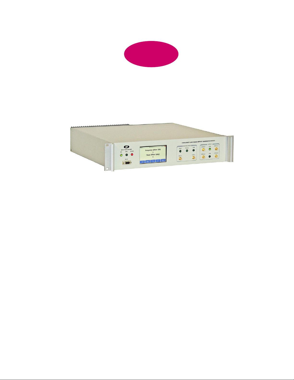
The HROG-5 is a high-resolution phase and frequency offset generator. The phase
and frequency of the output signals are adjustable with respect to a 5 MHz user
supplied reference. The output phase resolution of the generator is 2* /232 radians or
an output time step resolution of 0.3 fs. The output frequency resolution is 5 x 10-19.
Both phase and frequency steps are phase continuous.
The instrument provides two sine-wave outputs and two pulse outputs. The sinewave
outputs are buffered to provide greater than 80 dB of port-to-port and reverse isolation.
The outputs are at a level of +15 dBm. The pulse outputs are derived from the sine-
wave outputs by dividing by a factor of 5.0E6. The pulse outputs can be synchronized
to an external reference pulse to within 200 ns.
All instrument functions are displayed and controlled via the front panel LCD touch
screen. Remote control of the instrument is possible through RS-232 communications.
The HROG-5 comes in a stand-alone 2U rack mount enclosure.
Description
SDI
SPECTRADYNAMICS,INC •1849 Cherry St. Unit 2 •Louisville, CO 80027 •Phone: (303) 665-1852 •Fax: (303) 604-6088
www.spectradynamics.com
Se habla español

US Patent 6,278,330 Copyright © SpectraDynamics, Inc. 2010
3
CAUTION!
Voltages capable of causing injury or death are present in this instrument. Use extreme
caution whenever the instrument cover is removed.
Line Voltage
This instrument can be setup to operate on 110-120 or 220-240 VAC and a line
frequency of 50 to 60 Hz. The setup voltage for this HROG-5 is specified on
page 6. For conversion to a different line voltage please contact SDI.
Fuse
A 2.0 Ampere 250V slow-blow fuse is used for 100-120 VAC operation.
A 1.0 Ampere 250V slow-blow fuse is used for 220-240 VAC operation.
Only replace fuses with the same type and specifications.
Line Cord
The HROG-5 has a detachable, three wire power cord for connection to a grounded
power source. The enclosure of the unit is directly connected to the outlet ground to
protect against electrical shock. Always use an outlet with a protective ground and do
not disable this safety mechanism.
Service
Do not attempt to service or adjust the instrument unless another person, capable of
providing first aid or resuscitation, is present.
Operation
To operate the unit, locate the AC power entry connector on the rear panel and connect
the power cable. When power is applied to the unit, a green LED located on the front
panel, labeled “ON”, should light up.
Important!!!
The HROG-5 is a frequency and phase offset generator, therefore an external
reference is required for proper operation. The external reference provided should be
at 5 MHz +/-0.1Hz with a level of +10 to +15 dBm.
Safety and Preparation for Use
SDI

US Patent 6,278,330 Copyright © SpectraDynamics, Inc. 2010
4
ON The LED is on, when power is applied to unit and the unit is operating
properly.
DATA The LED is on when data is being sent or received via the RS-232 port.
STATUS The LED is on, when an error has occurred. View the instrument status
via the PLL screen. The LED will turn off once the error condition is
corrected or no longer present and the PLL status has been checked. If
the HROG-5 is under RS-232 control use the *SRE to determine the error
condition and the *CLS command to clear the status register and turn off
the STATUS LED.
RS-232 DB-9 connector for serial communications. This is a dumb terminal RS-
232 port. A null modem adapter is not required.
DISPLAY The LCD touch screen is used to control the HROG-5 in local control
mode.
REFERENCE INPUTS
5 MHz In SMA input for the external 5 MHz reference. This input port has an
impedance of 50 ohms. The external reference provided should be at
5 MHz +/- 0.1 Hz with a level of +10 to +15 dBm.
Signal LED The 5 MHz signal LED will turn on when a 5 MHz reference is present.
PLL LED The PLL lock LED will turn on when the HROG-5 is phase locked to an
external reference.
1 PPS In SMA input for an external one pulse per second signal (1 PPS) for
synchronization. This input port has an impedance of 1KΩ. The 1 PPS
signal should conform to TTL specifications and must not exceed +5.5
VDC. The voltage at this input must never be negative or the synthesizer
will be damaged and warranty voided.
1 PPS LED The 1 PPS indicator LED will flash when an external 1 PPS signal is
present.
The Front Panel
SDI

US Patent 6,278,330 Copyright © SpectraDynamics, Inc. 2010
5
OUTPUTS
5 MHz Out 1 SMA output number one providing the frequency and phase offset
5 MHz signal. This output signal has a level of +13 dBm.
Signal LED The 5 MHz signal LED will turn on when the 5 MHz outputs are present.
5 MHz Out 2 SMA output number two providing the frequency and phase offset
5 MHz signal. This output signal has a level of +13 dBm.
1 PPS Out 1 SMA output number one providing the frequency and phase offset
1 PPS signal. This output signal has a level greater than 2.2 V into a 50
ohm load.
1 PPS LED The 1 PPS LED will blink when the 1 PPS output is present.
1 PPS Out 2 SMA output number two providing the frequency and phase offset 1
PPS signal. This output signal has a level greater than 2.2 V into a 50
ohm load.
The Front Panel
SDI

US Patent 6,278,330 Copyright © SpectraDynamics, Inc. 2010
6
AC POWER ENTRY MODULE
The HROG-5 is configured to operate on:
100-120 VAC
220-240 VAC
The Back Panel
SDI

US Patent 6,278,330 Copyright © SpectraDynamics, Inc. 2010
7
RS-232 Communication Port
The HROG-5 functions are accessed through the RS-232 port located on the front
panel. A standard serial cable with a DB-9 connector can be used to interface to the
HROG-5. The user can input commands using a simple dumb terminal program on a
remote computer or more sophisticated control can be used with software such as
Labview.
On the front panel above the RS-232 connector there are three LEDs. The power LED
labeled ON should be lit when power is applied. The second LED labeled DATA will
light up only when data is being received or sent on the RS-232 port. This LED can be
used to verify that the unit is communicating. The third LED is labeled status and is a
hardware representation of the internal status flag. The status LED is on whenever an
error has occurred. The user must query the unit to determine the source of error and
then clear the error flag. When the error flag is cleared the LED will turn off.
Port Settings
On power-up the RS-232 port settings are:
Baud rate 9600 8 Bits 1 Stop Bit No Parity.
Hardware handshaking is not used. The DB-9 connector pinout is described below.
Pin Function
1 NC
2 Data out
3 Data in
4 NC
5 GND
6 NC
7 NC
8 NC
9 NC
RS-232 Port
SDI

US Patent 6,278,330 Copyright © SpectraDynamics, Inc. 2010
8
Mechanical Tuning
Mechanical frequency tuning is available to adjust the frequency of the internal
HROG-5 oscillator. Only fully qualified service personnel should perform this
procedure. Frequency adjustments should be made with the unit having been powered
on for at least 2 hours. Caution must be taken to avoid shorting or accidentally
touching a line voltage point.
1. To adjust the frequency of the oscillator, remove the top cover of the HROG-5.
The oscillator module is located at the right side of the instrument. The tuning
access for the 5 MHz oscillator is located on the top side of the oscillator
enclosure. A hermetic cover screw must be removed with a screwdriver to gain
access to the tuning screw. A small flat blade-tuning tool is needed to make the
adjustment.
2. Connect the external 5 MHz reference to the input labeled 5 MHz In. Make sure
that the reference signal level is between +10dBm and +15 dBm. Program the
HROG-5 to the nominal frequency offset that you want to use. For most
applications you may enter 0 Hz for the frequency offset.
3. Enter the PLL screen to view the RF power levels and control voltages. The
internal oscillator power level should be 12 1 dBm. The reference signal power
level should be between 10 dBm and 15 dBm. If the HROG-5 is phase locked to
the external reference the LOCK voltage will be greater than 0.2 V. Adjust the
mechanical tuning screw to achieve a lock condition. Continue adjusting the
mechanical tuning screw until the PLL voltage displayed is at 0 volts. At this
point the internal lock indicator LED should be on, the LOCK voltage should be
greater than 0.2 V and the PLL voltage should be at 0.0 0.2 V.
4. Replace all hermetic covers when done adjusting the frequency of the oscillators.
Replace the top cover of the HROG-5.
Note: The HROG-5 should be turned on for 2 hours prior to any mechanical
frequency adjustment.
Mechanical Tuning
SDI

US Patent 6,278,330 Copyright © SpectraDynamics, Inc. 2010
9
PARAMETER
CONDITIONS
MIN
TYP
MAX
UNITS
Phase Resolution
-
2(2-32)
-
radians
Phase offset range
-
infinite
-
-
Time offset resolution
5 MHz External Reference
-
0.3
-
fs
Frequency Resolution
-
5 E-19
-
-
Frequency Tuning Range
-
+/- 2 E-7
-
-
Mech. Tuning Range
-
+/-1 E-6
-
-
Int. Oscillator Aging
After 30 days of operation
-
1 E-10
-
Per day
5 MHz Output Level
50 Ohm Load
+10
+15
+17
dBm
1 PPS Output Level
50 Ohm Load
2.2
2.4
2.6
V
Output Isolation
Channel to channel
Reverse
-
-
80
80
-
-
dB
Phase Noise L(f)
Note: lower phase noise is
available.
10 Hz
100 Hz
1 kHz
>10 kHz
-
-
-
-
-135
-160
-165
-165
-132
-157
-162
-163
dBc/Hz
Allan Deviation y( )
f = 1.0 E-12
1 s
10 s
100 s
1000 s
-
-
-
-
2.1 E-13
3.2 E-14
2.0 E-14
9 E-15
-
-
-
-
Allan Deviation y( )
f = 0
1 s
10 s
100 s
-
-
-
1 E-13
2 E-14
2 E-15
-
-
-
Spurious
-
-110
-100
dBc
Harmonics
-
-45
-40
dBc
External Reference 5.0 MHz ± 2.0E-8 +10 dBm to +15 dBm
External 1 PPS 800 ns min. pulse width TTL Compatible Levels
AC Power 100–120 / 220–240 VAC see page 6.
Rack-mount Enclosure
Size: 3.5” X 19” X 17”
Weight: 28 lbs
Specifications
SDI

US Patent 6,278,330 Copyright © SpectraDynamics, Inc. 2010
10
Main Screen The main screen displays the current frequency and phase offset
of the HROG-5. The soft keys at the bottom of the screen display the five main
functions that are available.
DISPLAYS
Frequency Offset
The frequency offset may be displayed in units of Hertz (Hz) or as a fractional
number that is normalized to the reference frequency of 5.0 MHz. The frequency
units may be changed by the following key sequence:
SET, UNIT, FREQ.
Phase Offset
The phase offset may be displayed in units of degrees (deg) or as a time offset
in units of nanoseconds (ns). The phase units may be changed by the following
key sequence: SET, UNIT, PHASE.
STATUS
The status indicator is located in the upper right corner of the screen. Green
indicates normal operation and red indicates an error condition.
MENU
FREQ Change frequency command. The FREQ key will bring up the
Frequency Screen.
PHASE Change phase command. The PHASE key will bring up the Phase
Screen.
TIME Change time and date command. The TIME key will bring up the
Time Screen.
SET Change instrument settings. The SET key will bring up the Settings
Screen.
HELP Displays the Help Screen.
Main Screen
SDI

US Patent 6,278,330 Copyright © SpectraDynamics, Inc. 2010
11
Number Screen The number entry screen is used to make numeric entries.
DISPLAYS
The current setting will be displayed across the top of the screen. The new entry
is displayed in a number entry box.
SPECIAL KEYS
Hz Enter number in Hertz.
uHz Enter number in microHertz.
deg Enter number in degrees.
mdeg Enter number in millidegrees.
ns Enter number in nanoseconds.
ps Enter number in picoseconds.
BK Backspace.
ENTER Enter new number and exit number menu.
ESC Exit number menu discarding changes.
0-9 Numbers zero through nine.
.Decimal point.
- Negative sign
+Positive sign.
EXP Exponential
Number Entry Screen
SDI

US Patent 6,278,330 Copyright © SpectraDynamics, Inc. 2010
12
Frequency Screen The frequency screen displays the current frequency offset of the
HROG-5. The soft keys at the bottom of the screen are used to set a new
frequency offset.
DISPLAYS
Frequency Offset
The frequency offset may be displayed in units of Hertz (Hz) or as a fractional
number that is normalized to the reference frequency of 5.0 MHz. The frequency
units may be changed by the following key sequence:
EXIT, SET, UNIT, FREQ.
MENU
SET Enter new frequency offset. The SET key will bring up the Number
Entry Screen. The maximum frequency offset is +/- 1.0 Hz or
2.0E-7. The frequency offset resolution is 5.0E-19.
STEP Enter a frequency step size. The STEP key will bring up the
Number Entry Screen. The maximum step size is 2.0E-7.
Frequency step resolution is 5.0E-19.
UP Increase the frequency offset by the frequency step size.
DOWN Decrease the frequency offset by the frequency step size.
EXIT Exit to previous menu.
Frequency Screen
SDI

US Patent 6,278,330 Copyright © SpectraDynamics, Inc. 2010
13
Phase Screen The phase screen displays the current phase offset of the HROG-5.
The softkeys at the bottom of the screen are used to set a new phase offset.
DISPLAYS
Phase Offset
The phase offset may be displayed in units of degrees (deg) or as a time offset
in units of nanoseconds (ns). The phase units may be changed by the following
key sequence: EXIT, SET, UNIT, PHASE.
MENU
SET Enter new phase offset. The SET key will bring up the Number
Entry Screen. The difference between the new phase offset and
the current phase offset must be less than 3600 degrees or 2000
ns. The phase slew rate is 9 degrees/second or 5 ns/second. The
phase resolution is 8.4E-8 degrees or 0.3 fs.
STEP Enter a phase step size. The STEP key will bring up the Number
Entry Screen. The phase offset step size is limited to 3600 degrees
or 2000 ns. The phase step resolution is 8.4E-8 degrees or 0.3 fs.
UP Increase the phase offset by the phase step size.
DOWN Decrease the phase offset by the phase step size.
EXIT Exit to previous menu.
Phase Screen
SDI

US Patent 6,278,330 Copyright © SpectraDynamics, Inc. 2010
14
Settings Screen The settings menu is used to access, view and edit instrument
options.
MENU
UNIT Change phase or frequency units.
PHASE Press the PHASE key to toggle phase units. Options are:
Phase units in degrees
Time units in nanoseconds
FREQ Press the FREQ key to toggle frequency units. Options are:
Frequency units in Hertz
Fractional frequency with reference to 5.0 MHz
COMM RS-232 options and control. The COMM key will bring up the
Communications Screen.
PPS 1 Pulse per second output options and control. The PPS key will
bring up the 1 PPS Screen.
INST Instrument setup and information. The INST key will bring up the
Instrument Screen.
EXIT Exit to previous menu.
Settings Screen
SDI

US Patent 6,278,330 Copyright © SpectraDynamics, Inc. 2010
15
Communications Screen The communications screen displays the current RS-232
serial port settings. The soft keys at the bottom of the screen are used to set
new RS-232 settings, initiate RS-232 control of the instrument or test the serial
port connection. The RS-232 port is setup to be controlled by a dumb terminal.
A null modem adapter is not needed and should not be used. Hardware
handshaking is not used. For additional pin-out information please refer to the
RS232 port section on page 7 of this manual.
DISPLAYS
Current Baudrate setting.
MENU
REM Enter remote RS-232 control mode.
BAUD Toggle through available baudrates.
9600, 19200, 38400, 57600, 115200, 14400, 28800
TEST Used to test the RS-232 connection. Sends the following string
through the serial port:
“Testing Serial Port”
“Hit Enter to Continue”
LOCAL Return to local control and terminate remote RS-232 control
session.
(This button appears only in remote RS-232 control mode).
EXIT Exit to previous menu.
SDI
Communications Screen

US Patent 6,278,330 Copyright © SpectraDynamics, Inc. 2010
16
1 PPS Screen The 1 PPS screen displays the current 1 PPS generator settings.
The soft keys at the bottom of the screen are used to change the 1 PPS settings
and synchronize to an external 1 PPS source.
DISPLAYS
Mode The 1 PPS generator can be in 1 PPS mode generating an output
one pulse per second signal, or in test mode generating a 50 Hz
test signal.
PW The pulse width of the one pulse per second output signal.
MENU
RST Reset the 1 PPS counter, used for diagnostics only.
TST Toggle between 1 PPS and TEST mode. The TEST mode will
generate a 50 Hz test signal.
SYNC Synchronize the output 1 PPS to an external 1 PPS signal. The
time difference between the output 1 PPS and external 1 PPS
should be less than 200 ns for a successful synchronization. A
timeout error will occur if no external 1 PPS signal is present.
SPW Toggle through the available pulse width settings of the 1 PPS
signal.
Pulse width options:
0.8 us, 3.2 us, 12.8 us, 51.2 us, 102.4 us, 204.8 us, 409.6 us, 819
us
EXIT Exit to previous menu.
1 PPS Screen
SDI

US Patent 6,278,330 Copyright © SpectraDynamics, Inc. 2010
17
Instrument Screen The instrument screen is used to view or instrument configuration
settings.
MENU
REG View center frequency and the frequency registers, reset the phase
counter and view reference frequency.
RPHS Reset the phase offset counter to zero.
NVAL View the frequency registers.
REF (Factory setting) View the frequency that is used as the
external reference. The external reference frequency is not
user selectable and must not be changed.
DISP Change the contrast of the LCD display.
UP Increase the value.
DOWN Decrease the value.
EXIT Exit to previous menu.
PLL View phase-lock-loop control voltages and levels. The PLL key
brings up the PLL window.
EXIT Exit to previous menu.
Instrument Screen
SDI
US Patent 6,278,330 Copyright © SpectraDynamics, Inc. 2010
18
PLL Screen The PLL Screen is used to view the current PLL voltages and RF
power levels. Use this function to clear the status register and turn off the status
LED. Note that the status LED will turn off only if the error condition has been
resolved.
DISPLAYS
OSC The power level of the internal oscillator. This level should be +12
dBm 1 dB.
REF The power level of the external reference. This level should be
between +10 dBm and +15 dBm for proper operation.
LOCK The lock indicator voltage. A voltage greater than or equal to 0.2 V
indicates that the HROG-5 is phase locked to the external
reference.
PLL The tuning port voltage on the HROG-5 internal oscillator. For
proper operation the tuning port voltage is 5.0 V. If the voltage
displayed is within 0.5 V of these limits the internal oscillator may
need to be mechanically tuned. Please refer to the mechanical
tuning section on page 8 of this manual for more information.
TEMP The internal instrument temperature in degrees Celsius.
MENU
Exit Exit to previous menu.
PLL Screen
SDI
Table of contents
Popular Inverter manuals by other brands

Chint Power
Chint Power CPS SCH Series Installation and operation manual

iENERGY
iENERGY i-Manager installation guide

Siemens
Siemens SINAMICS G120P Hardware installation manual

DieHard
DieHard Diehard 200.71522 Operator's manual

Danfoss
Danfoss VLT AutomationDrive FC 360 quick guide

Soltaro
Soltaro AIO2 Customer information

Zeversolar
Zeversolar Eversol-TLC 10K Installation and operating istructions

AC Tech
AC Tech Lenze SV01B operating instructions

SolaX Power
SolaX Power X3-Retro Fit Series Quick installation guide

Shihlin electric
Shihlin electric SE2 Series manual

Power Electronics
Power Electronics Freesun String Supervisor SFS08 Getting started manual

Generac Power Systems
Generac Power Systems 00941-4 Owners and installation manual


