Royal-model DG-300 Instruction Manual

Congratulations! You have just bought the model plane which is a semi-replica of
a real glider being manufactured in Germany. The model is designed to be used by
advanced modelers, mainly for the on-slope flights, but you‘ll certainly appreciate
its good flight performances in the conditions of thermals too. The model can also
be fitted with a hook to be pulled behind a motor aircraft.
Kit includes:
White gel-coated fiberglass fuselage, fiberglass rudder, balsa elevator, foam/abachi two-piece
wings covered with foil, double-high airbrakes installed, canopy frame, clear canopy, hardware,
instruction
To finish the model you need:
* cyanoacrylate adhesive
* 5-min epoxy glue
* common modeller’s tools (sharp knife, drilling machine, screwdriver, fine round
file,sandpaper)
To fly you need:
* 4 channel RC set and 6 servos
CAUTION! You are responsible for running this model. A damage to property or health might
arise by improper use of this product. This is why you have to keep a safe distance from the
buildings and other developed areas when flying. Make sure that you are the only one who is
flying on the same waveband.
The product may only be used by the children over 14, supervised by adults.
¼ Semi-scale sailplane
DG-300
royal
royalroyal
royal
-
--
-
model
modelmodel
model
Building instructions
3750 mm 4000 g (empty)
1720 mm HQ 2,5/14
67 dm
2
A, E, R, B

FINISHING THE MODEL
On its substantial parts your model have already been lined with the ironing foil.
The glider is ready to fly right after the installation of the RC set.
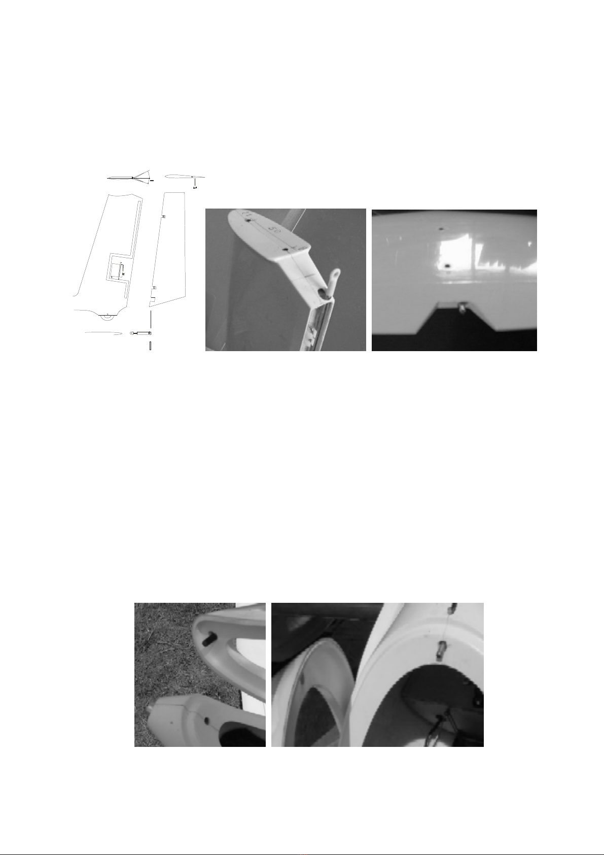
1, Fuselage and wing installation
Make the marked holes for the wing-fixing dowels and steel wires and enlarge them to 18 mm
diameter. All the appropriate holes in the fuselage must fit those in the wing, therefore, first
assemble all parts together without glueing them. Glue the brass tube for the fixing wire into the
fuselage. Be carefull not to glue the wire or the wing halves themselves to the fuselage by using
an excessive amount of glue. Temporarily fix all parts together and let the glue dry.
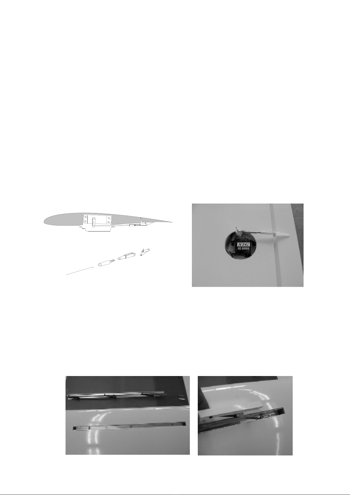
2. How to install the ailerons servos
Install the extension servo cables into the wing. Connect the extension cables to the servos
(connectors or soldering -in this case isolate the wires using the heat shrinking tube). Attach the
control horns to the ailerons. Fix the ailerons in the neutral position using pieces of a self-
adhesive tape. Install single levers to the servos, adjust them to the neutral position and insert the
servos into the holders - without fixing them now. Prepare 2 rods made of 1mm diameter wire
with „Z“- bend on one end ,measure and cut the wires to the proper lengths and solder the brass
endings. Screw in the clevises. Remove the servos, insert the „Z“-bend into the servo lever, and
fix the servos in the holders using a quality double-side self adhesive tape. Connect the pushrods
to the control horns. Cover the servos with the hood.
3. How to install the servos to the airbrakes
Attach the servos with two-sided Scotch tape to the channel and join them with the dive flap
using a draw rod. You will need extension cables and a Y-cable.
Shade your spoiler by pushing slightly with a small flat screwdriver on the arms of the bar (black
parts). Pull the Z of the manoeuvring on the gilded part and insert it into the interlocking hole
connecetd with the bottom of the servo. Shade again your spoiler and screw down your clevis at
the end of the manoeuvring. Demonstrate your servo heeding that the manoeuvring arm of the
servo is in the position of closed spoilers of your radion manoeuvring. (Example full gas on the
way of the engine manoeuvring of your radio) Adjust your manoeuvring and glue your servo
after having checked that both spoilers servos are moving in the right direction. Cover the servos
with the sheet.

4. How to install the elevator servo
Glue the rudder support - steven into the fuselage. There is an opening for a servo in the steven.
Elevator is controlled by the servo screw inside the rudder with its drive forces being transmitted
via a pull-rod. This approach allows the elevator to be driven without any play. Stick the micro-
servo into the lower fin, leading the extension cable through the fuselage. Make a bearing to
guide the steel pull-rod on the elevator. Solder a threaded piece onto the pull-rod end (on the
servo side) and screw in the fork. Shorten the pull-rod as necessary. Fit the pull-rod onto the
servo.
5. Rudder installation
The rudder is mounted on clip-on hinges. Cut out the notches for rudder hinges with a razor
blade, insert the hinges inside, fixing them with a lean instantaneous cement. Clip the rudder to
hold.
Find the position of the rudder control horn so that the straight line connecting the holes in the
horn and the axis of rotation of the control surface is perpendicular to the surface of the stabilizer
and the horn itself is in the same level as the control wire coming from the fuselage. Glue the
rudder horn. The rudder is controlled by a pull-wire drive. Attach the terminals to the rudder and
join them with a servo using a pull-wire drive.
6. Fitting the cockpit
Cut out the cockpit transparent section using the mark line, glue it onto the plastic cockpit, trim it
then and grind a bit off to a desirable shape.
The cockpit is held in place with a pin and cockpit lock. Bore then the matching holes in the
fuselage and in the cockpit. Glue the pin in the front canopy. Glue the cockpit lock in the
fuselage.

7. How to install the radio and batteries
Glue the servo holder plate in the fuselage and install the control servo close to the servo holder
plate. Make an opening for the RC receiver switch and install it. Insert the battery and the
receiver into the fuselage. Use foam to protect them from vibrations and impacts. Connect all
components as necessary. Use a Y harness to connect the aileron servos to one channel only or
use two channels for ailerons, if available.
8. Finishing the model
The wing halves can be secured in the right position either by self-adhesive tape or using a
rubber ring. In this case make 1.8 mm holes in the first wing ribs and screw in the hooks for the
fixing rubber ring. Drill the holes in the proper position in the fuselage for the rubber ring. In
case of using this model for thermal soaring, attach the tow hook
Applying the decorative stickers is the last step to finish your model.
FLYING
Check the centre of gravity position (75-80 mm), add some lead if necessary, don`t forget to
check the symmetry of the whole model. Once on the field, first check the function of your RC
set and check the range, too. Calm wheather is the best for the first flights. Try hand launching,
trim if required for optimal gliding. Provided that everything is in order, you can go for the
maiden flight, with a charged battery of course.
Fluctuations recommended (in mm terminal bow for ailerons, clacks and elevator)
Ailerons : +14 -6. Elevator : + 5 -4. Rudder : 32 et 32.
Centrage : from 75 to 80 mm from the leading edge for the first flight and move it back to your
liking.
Have a lot of fun and many happy landings with your DG-300.
Table of contents
Popular Toy manuals by other brands

Reely Sky
Reely Sky EC 135 operating instructions

The World Models Manufacturing
The World Models Manufacturing GROOVY 3A 50 instruction manual

E-DOMODEL
E-DOMODEL Yak54 ST Assembly instructions

Eduard
Eduard WEEKEND Series quick start guide

Meccano
Meccano 18203 instructions

Mega Bloks
Mega Bloks Skybright Airport quick start guide

Mega Bloks
Mega Bloks ASSASSIN'S CREED CNG07 manual

Fisher-Price
Fisher-Price smart cycle Assembly Tip

GRAUPNER
GRAUPNER ROMMEL operating instructions

Black Horse Model
Black Horse Model P47 Thunderbolt Instruction manual book

TRANSFORMERS
TRANSFORMERS CYBERVERSE POWER OF THE SPARK SCRAPLET instructions

Fisher-Price
Fisher-Price Read with me DVD Quick set-up quick set-up instructions