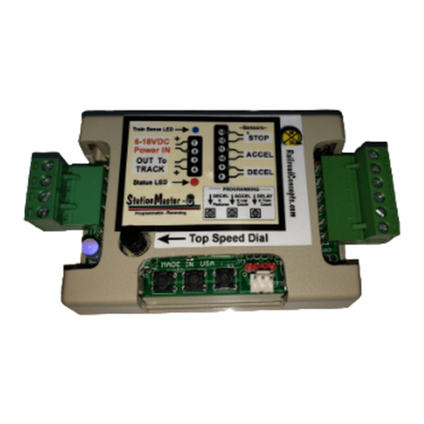
RR-Concepts StationMaster-SHUTTLE User manual

1
The StationMaster-SHUTTLE can perform hands-off back-and-forth operations using realistic
accelerations and decelerations. By using end of track sensing, no programming or adjusting
is needed. Just place the train on the track and power up.
The StationMaster.SHUTTLE can control DC trains or DCC trains set to linear mode.
Before we Start- Please do not attach power wires (from your power pack or
transformer) to any other terminals except the designated input pins 1 and 2.
Your StationMaster will be damaged if power is put on any terminal other than 1 and 2.
ONLY ATTACH WIRES WHILE THE POWER IS OFF.
Quick-connect terminals allow easy swap-out and removal of the electronics while leaving
the wires in place. The RR Concepts Magnet/Screwdriver tool is recommended for wire-up
and testing of operations.
tation aster -
Model Train Reverser
Status LED
Speed Adjust and
Programming Dial Out to YardMaster data
cable connector.
IN 8-24VDC
Out to Track
Train Sense LED
Programming
Pushbuttons
In-between
Stop sensor
SM
April, 2023
SHUTTLE
See decal on bottom for optional programming information
Signal Light connector
4 AMP version shown
C
RR
RR Concepts

2
Train Detected LED
Speed Adjust and
Programming Dial
IN 8-24VDC
Out to Track
See the label on the bottom for programming and additional information.
Status LED
In-Between
stop sensor
tation aster
Quick Hookup Instructions
SM
SHUTTLE
The StationMaster works with DC (out of the box)
or DCC trains set to linear mode. (N, HO, G, etc.)
AC trains cannot be controlled.
To
Power Pack
TRACK
Terminals or fixed
DC power source.
To
TRACK
1
2
3
4
8
9
10
11
12
13
StationMaster
SCAN FOR INFO
5 AMP Version shown, Also available in 10 AMP configuration.
Shuttle CONNECTIONS and CONTROLS
Basic Hookup for Realistic
Accelerations and Decelerations
RR Concepts
C
RR
Un-modified trains.
No sensors, no
magnets.
It just works!
Hookup Instructions:
1) Attach terminals 1 & 2 to the transformers TRACK
output.
2) Attach terminals 3 & 4 to the track. No polarity.
3) Attach diodes to end sections where the train
will stop.
4) Turn on the transformer or supply DC voltage. If the StationMaster does
not light up then reverse the direction on the transformer.
See the online manual for in-between stops, and optional programming
for delay times, acceleration/deceleration rates, and Manual Mode.
Auxiliary Relay
connector
Reset Manual
Mode SET

3
Operations
C
RR
RR Concepts
Fully Automatic Mode:
Instructions: let the train run and watch.
Learning Mode:
After a factory reset the Shuttle will be set for Automatic mode. After each power up while in
automatic mode the Shuttle will run the train back-and-forth for three times, measuring the
distance between the ends. If upon power up no train is sensed for the first 10 seconds, then
the Shuttle will reverse and run the other direction. This could be the case where the train
starts up in a diode section. While in learn mode the blue LED will be on.
Running Mode:
After learning is complete the Shuttle will self-adjust each time until a perfect run is obtained
and the train is running realistically. The self-adjusting allows anyone to change the speed of
the train and let the Shuttle self-adjust to the new speed. The train may stop short a few
times, or come to the ends faster than expected, but the Shuttle will eventually run perfectly
and realistically. When running automatically the green, red, and orange LEDs will turn on.
Creeping Into the Ends:
When approaching the ends, the Shuttle will decelerate the train and then creep until reaching
the end. The length of time for creeping is determined by the deceleration rate. A faster deceleration
will result in a shorter creep, while a slower deceleration (more blinks) will creep longer.
Adjust to what looks good since each train or trolley will behave differently.
Top Speed Adjustment:
The top speed of the train is set by either adjusting the transformers throttle, or by using the
top speed dial. In some trains the lights and smoke will stay on when running slowly if the
transformer throttle is set high and the top speed dial is used to slow down the train.
Button #1 will reset the Shuttle and start the learning process again.
Notice that not all trains will run perfectly while in automatic mode. Because the Shuttle uses
“current sensing” to see the trains, some trains with very small motors may not
reliably run. If the creeping speed set by the Shuttle is very fast, or the trains never reach the
ends after dozens of runs, then Manual Mode can be used.
Top speed dial
Reset

4
Operations
C
RR
RR Concepts
Manual Mode:
Manual Mode allows complete control of deceleration operations and creeping speed and will
operate with all trains. This could be used for super-realistic control if wanted, or if the train has
extremely small motors which the SHUTTLE cannot reliably sense.
When in Manual Mode, the Shuttle will stay in manual mode after each power up and never enter
automatic mode until Automatic mode is reset by pressing button #1, or performing a factory reset.
In Manual Mode button #3 is used to set the start of the deceleration. When button #3 is pressed
the shuttle will go into manual mode and remain in this mode until reset.
How to set the “Start Decelerate” location:
Press button #3 when the train reaches the location where you want the deceleration to start. After
deceleration the train will creep into the ends. Button #3 must be pressed in both directions.
The Blue LED will be on when button #3 needs to be pressed.
When running normally, button #3 can be pressed at any time to set a new deceleration location.
When running, the top speed dial can be used to set the creeping speed into the stops. If set too low
the train might stop before reaching the ends. Adjust to what looks good.
To exit manual mode and return to automatic mode, press button #1 or perform a factory reset.
Creep Speed
Adjust
Reset and exit
manual mode
Set deceleration
location for each
direction
Blue indicates
learn mode

5
RR Concepts
C
RR
Input Power
The Shuttle is usually installed between the train transformer and the track, however a fixed
DC power source could also be used. The Shuttle can accept voltages up to 24 volts.
In all cases the voltage should be pure DC and not “pulsed” or PWM. Some electronic
speed controllers use pulsed voltage which may not be compatible with the Shuttle.
Variable Speed Transformer Hookup:
Attach terminals 1 & 2 to your transformer's DC output (Sometimes labeled as TRACK)
and set the throttle to the running speed of the train. If the running speed of the train is
very slow (under 8 volts), then turn up the throttle on the transformer and use the top speed
dial on the Shuttle to reduce the train speed. If the Shuttle does not light up then reverse the
direction on the transformer. The Shuttle will be in bypass mode when the voltage polarity
is reversed and there will be no control.
Fixed Voltage Source Hookup:
Since the Shuttle controls the speed of the train, a variable speed transformer is not required
and a fixed DC power source could be used. Usually a 12 volt DC power source is a perfect
solution and these can be obtained quite inexpensively. Attach the voltage source to pins 1 and
2 and use the top speed dial on the Shuttle to set the running speed of the train. If the Shuttle
does not light up then reverse the wires on pins 1 and 2. The Shuttle will be in bypass mode
when the voltage polarity is reversed and there will be no control.
Attach terminals 3 & 4 to your track, either rail.
+
-

6
In-Between Station Stops
Place MAGNET
on bottom of engine.
Place MAGNET
on bottom of engine.
Sensors in PARALLEL.
For in-between stops, attach a sensor to terminals 10 and 11. When the
magnet on the train triggers the sensor the train will pause at the station.
For more than one stop add more sensors in parallel.
Note that The deceleration rate is rapid and the time duration for the stop is fixed.
This allows the train to stop at approximately the same location for each direction.
Terminals 10 and 11
Terminals 10 and 11
One Stop
Many Stops
Tip for Advanced Users:
The station stop will only be active
while the train is “cruising” (Solid
green LED showing) It is possible to
have 2 sensors at a station stop; one
for each direction where the train
stops between them. The 2nd sensor
encountered would be ignored while
the train is accelerating.
C
RR
RR Concepts

7
Top Speed and Programming Mode Dial
The Top Speed dial provides 3 functions:
1: Adjust the top "cruising" speed of the train when in automatic mode.
2: Reduce the “creeping speed” when running in manual mode.
3: Enter programming mode.
Automatic Mode Top speed adjustment
“Full speed" is clockwise. Turn this dial down as necessary to set the desired cruising
speed of the train. This is only necessary when using a fixed voltage power supply
or when a YardMaster is attached and a slower top speed is desired.
Typically, this dial is set fully clockwise and the train throttle (transformer) is used
to set the speed of the train.
Manual Mode Creep Speed adjustment
When in “Manual Mode” turn this dial down to reduce the creeping speed of the train as
it enters the diode sections.
Programming Mode
To enter programming mode turn this dial fully counter-clockwise. The blue Train Detect LED will
“twinkle” to indicate “programming mode”.
To exit programming mode turn the dial fully clockwise.
C
RR
RR Concepts

8
Blue “twinkle”: Train is not sensed on power up. After 10 seconds the train will
reverse.
Blue Not Flashing: Manual Mode: Shuttle is performing the learn operations.
Manual mode: button #3 must be pressed to set deceleration start location.
Blue Flashing once a second: Shuttle is performing a time delay operation and is
still self-adjusting. (See orange flashing)
Green: Train is accelerating and running normally.
Red: Train is decelerating and operating normally.
Orange: Train is creeping into the diode section.
Orange flashing once a second: Shuttle is performing a time delay with all self-adjusting
completed.
Red blinking indicates an over-current SHUTDOWN.
To recover: Turn power off then back on. If the condition returns after recovery then check for a
short circuit on the track or re-program the shutdown threshold by turning transformer
to full speed and pressing button #3 for 5 seconds while flashing.
Train Sense LED indicates a train is sensed. When twinkling the Shuttle is in programming
mode. Turn the top speed dial clockwise to exit programming mode.
Blue Train Detected LED
Red/Green/Blue STATUS LED
LED indicators
Status LED
Status LED
Status LED
Status LED
C
RR
RR Concepts
Status LED
Status LED
Status LED
Status LED
Train Sense LED

9
1. Make sure all three sensor inputs are open.
2. If the top speed dial is not already at zero, then turn the top speed dial to zero.
(fully counter-clockwise.) The Blue “Train Detected” LED will “twinkle”
3. Push and hold programming button #1.
4. Watch the status led. Each RED blink will decelerate slower.
The fastest deceleration will be with one blink. (TRAIN Stops
sooner) Release the pushbutton when the desired number of blinks have occurred.
A typical number is 5. Repeat this procedure if you want a different value.
One blink corresponds to a 3 second deceleration rate. Each additional blink adds
1 second. For example, a blink count of 5 would result in a deceleration rate of
8 seconds.
In Automatic mode the deceleration rate will also determine the creeping time.
A longer deceleration will allow the train to creep for a longer duration before entering
the stops.
When finished with all programming turn the top speed dial fully clockwise and
then turn down to a desired top speed if needed.
All programming values are stored in flash memory and are retained until
re-programmed.
Programming:
Deceleration Rate
Fully
counter
clockwise
C
RR
RR Concepts

10
1. Make sure all three sensor inputs are open. (Red LED is off)
2. If the top speed dial is not already at zero, then turn the top speed dial to zero.
(fully counter-clockwise.) BlueTrain Detected LED will “twinkle”.
3. Press and hold programming button #2..
4. Watch the status led. Each GREEN flash will accelerate slower.
The fastest acceleration will be with one blink.
Release the button when the desired number of blinks have occurred.
A typical number is 5. Repeat this procedure if you want a different value.
One blink corresponds to a 3 second acceleration time. Each additional blink adds
1 second. For example, a blink count of 5 would result in a acceleration rate of
8 seconds.
When finished with all programming, increase the top speed dial clockwise
to MAX and then down to a desired top speed. All programming values are stored
in flash memory and are retained until re-programmed.
A Note on Realistic Accelerations:
* For blinks 1 thru 9 the train will accelerate linearly with the programmed value.
This is typical for trolleys.
* For blinks 10 and above the train will creep very slowly out of the station
and then continue accelerating as it continues down the main line.
This provides a very realistic operation as a train creeps out of a siding or station
and shows off sound systems with incredible realism.
* 10 blinks will creep for 5 seconds.
* 11 blinks will creep for 10 seconds.
* 12 blinks and up will creep for 15 seconds.
Programming:
Acceleration Rate
Fully
counter
clockwise
C
RR
RR Concepts

11
1. Make sure all three sensor inputs are open. (red Led is off)
2. If the top speed dial is not already at zero, then turn the top speed dial to zero.
(fully counter-clockwise.) BlueTrain Detected LED will “twinkle”.
3. Press and hold programming button #3.
4. Each ORANGE flash will increase the waiting time after a station stop.
A wait time of zero will be with one flash.
Release the button when the desired number of flashes have occurred.
Repeat this procedure if you want a different value.
The LED will turn orange when an infinite delay is set (after 13 counts).
When infinite delay is set, then the Accel sensor is required to start up the train
after stopping.
A fun thing to do would be to connect the ACCEL terminals to a
doorbell switch. Your train would patiently wait until someone pushed the button! Motion
sensors are another possible way to start the train.
When finished with all programming increase the top speed dial clockwise to
maximum or to a desired top speed. All programming values are stored
in flash memory and are retained until re-programmed.
The number of orange FLASHES will correspond to the following
time delays:
1: 0 seconds, no wait.
2: 5 seconds
3: 10 seconds
4 15 seconds
5: 20 seconds
6: 30 seconds
7: 1 minute
8: 2 minutes
9: 5 minutes
10: 10 minutes
11: 30 minutes
12: 60 minutes
13: Infinite, wait for ACCEL sensor.
Programming:
Pause Time
Fully
counter
clockwise
C
RR
RR Concepts

12
Programming:
Advanced Settings
BLUE
C
RR
RR Concepts
HOW TO PROGRAM: (A factory reset will clear everything)
1. Enter Secondary Programming mode: (Skip this step if already in secondary programming mode)
* Turn the Top Speed dial fully counter-clockwise to enter programming mode
(Skip this step if already in programming mode).
* Turn the Top Speed dial slowly clockwise until the LED turns green. This indicates
secondary programming mode. This should be about half-way.
2. Quickly press button #1 to view current settings or press and hold programming button #1
until the desired number of blinks have occurred. The Shuttle will echo the programmed settings
with four blinks. A green blink indicates the setting is ON, while a red blink indicates the
setting is off.
Each blink will set or clear a different feature. If currently ON it will turn off. If ON it will turn OFF.
Programmable Settings: (Any or all of these or all can be programmed independently)
Hold button for 1 blink = Fire the YardMaster in both directions. This is needed for some
switching hookups such as a switch-back operation.
Hold button for 2 blinks = Send an alternate signal to the YardMaster. This is needed for
some switching hookups.
Hold button for 3 blinks = Disable the shutdown. This is sometimes needed when a very small
transformer is used which causes false shutdown errors. Notice that
the Shuttle could be damaged if the shutdown is disabled while using
a large power source.
Hold button for 4 blinks = Resume Running. For Automatic Mode only, do not enter learning
mode on power up. Run with all adjusted settings from last time.
Manual mode will always resume running.
When the button is released the Shuttle will echo the currently programmed settings with three
blinks of either red or green.
For example, if “Send alternate signal to YardMasters” has been set (button pressed for 2 blinks,
and nothing else is set, then the Shuttle will blink:
blink 1 RED: “Fire the YardMaster in both directions” is OFF.
blink 2 GREEN: “Fire YardMaster before acceleration” ON.
blink 3 RED: “Disable the shutdown is” OFF
blinlk 4 RED: “Resume Running” is OFF.
Each time a setting is programmed that feature will toggle on or off. (Toggle means the feature will
go OFF if currently ON, or ON if currently OFF). In the example above, holding down button #1 for
two blinks a second time will turn off the previously set value. A factory reset will clear all settings.
To view the currently programmed operating modes quickly press and release button #1.

13
HOW TO PROGRAM: (Perform a factory reset to clear everything if needed)
1. Enter Secondary Programming mode: (Skip this step if already in secondary programming mode)
* Turn the Top Speed dial fully counter-clockwise to enter programming mode
(Skip this step if already in programming mode). The blue Train Detected LED will “twinkle”.
* Turn the Top Speed dial slowly clockwise until the LED turns Green.
2. Press and hold programming button #2 until the desired number of blinks have occurred.
Programmable Modes:
Hold button for 1 blink = Station Stop mode, Relay On when decelerating and stopped.
Hold button for 2 blinks = Direction mode, Relay On when forward, Off when reversed.
Hold button for 3 blinks = Pulse at stop
To view the currently programmed operating mode quickly press and release button #2.
Programming:
External Relay
BLUE
C
RR
C
RR
RR Concepts
Additional notes for usage:
* The “pulse” modes could be used to trigger an external sound module or other device.
* It is also possible to use this header to directly trigger another StationMaster or YardMaster
without the relay. For example, just as one Shuttle stops a train it could then trigger
a second Shuttle or StationMaster to start up. Consult RR concepts for details.
DPDT Auxilliary relay with cable
Available at RRConcepts.com
External Relay / Signal Light Control
The StationMaster SHUTTLE can control external devices when an Auxiliary relay is attached.
The default setting is for a station stop signal light.
When decelerating, creeping, or stopped, the relay will be ON; for all other cases
the relay will be OFF. When a signal light is attached to the relay it could show
RED when entering at the station, and GREEN when leaving.
This relay can also be configured to turn the relay ON or OFF based on the train direction,
or momentarily switch when the train stops. This could be used for station sound affects, etc.

14
Programming:
Factory Reset
To set the StationMaster back to factory defaults perform the following:
1: Enter programming mode by turning the top speed dial fully
counter-clockwise.
2. Press and hold both button #1 AND button #3 at the same time.
3 Turn the top speed dial fully clockwise to exit programming mode.
Fully
counter
clockwise
C
RR
RR Concepts
The factory default settings are:
* Acceleration rate 3 blinks
* Deceleration rate 4 blinks.
* Time delay 10 seconds.
* Train count: 1
* Operating mode:
Blink 1 = RED, Fire YardMaster in both directions OFF.
Blink 2 = RED, Send alternate signal to YardMasterr OFF.
Blink 3 = RED, Disable shutdown current sensor OFF.
Blink 4 = RED, Resume Running OFF.

15
The train count is needed for 2 reasons:
1. Manage different creeping speeds for up to 3 trains when wired in a siding hookup .
2. Send proper signals to attached YardMasters to correctly fire turnouts.
A factory reset will set this to 1 train.
Programming:
1. Make sure all three sensor inputs are open.
2. If not already in programming mode, turn the top speed dial to zero.
(fully counter-clockwise.)
3. Slowly turn the top speed dial clockwise until the LED turns GREEN.
This indicates secondary programming mode.
(Skip this step if already in secondary programming mode)
4. Press and release button #3 quickly to see the current setting, or press and
hold button #3 for the desired number of blinks to set a new train count.
After the button is released the train count setting will be echoed back.
Repeat this procedure if you want a different value.
When finished with all programming, increase the top speed dial clockwise to MAX,
and then down to a desired top speed if necessary.
All programming values are stored in flash memory and saved until re-programmed again.
Programming:
Train Count
Blue
C
RR
RR Concepts

16
When in Manual Mode, (button #3 was pressed) the top speed dial is used
to adjust the creeping speed into the stops.
When a fixed voltage DC transformer is used, the top speed of the
train can be programmed to slow down the train. This value is retained until
changed, or reset after a factory reset. This setting has no affect in Automatic mode.
HOW TO SET A TOP SPEED:
1. Enter Tertiary Programming mode: (Skip this step if already in tertiary programming mode)
* Turn the Top Speed dial fully counter-clockwise to enter programming mode
The blue “Train Detected” LED will “twinkle”
* Turn the Top Speed dial slowly clockwise until the LED turns Green and then BLUE.
This indicates tertiary programming mode.
* After 3 seconds the currently programmed speed will be put on the track and the train will run.
2. Press and hold button #1 to decrease the speed, or button #2 to increase the speed.
Watch the train and choose a value that works. The speed changes slowly so keep
holding down the buttons.
3. When the train enters the stops, press button #3 to reverse directions.
4. After a good speed is determined, turn the top speed dial fully clockwise to exit
programming mode. This speed value will be stored in flash memory.
Programming:
Fixed Top Speed
BLUE
C
RR
RR Concepts
-Manual Mode only-

17
Automatic Shutdown Details
The Shuttle has advanced electronics and software which will attempt to
protect itself and also your trains when potentially disastrous events occur.
Some transformers know their current capability and will shut down when a current
threshold is reached but for sensitive electronics this is sometimes
too late. The StationMaster determines what a short circuit is by causing is very
brief short circuit after a factory reset, and then records the event. When that event
happens again the StationMaster will shut down and blink the red and blue LEDs.
HOW TO RESET THE SHUTDOWN THRESHOLD
The shutdown threshold is set after a factory reset. Make sure the
train transformer is set to 100% when exiting programming mode. The Shuttle will
short the track and then record the new value. If the train transformer was set to a
low speed then a bad value would be recorded which could cause false shutdowns.
It is also possible to reset the shutdown threshold when the Shuttle is in the red flashing
shutdown condition. When in the shutdown state, press and hold button #3 for 3 seconds.
Make sure the transformer is at 100%. This allows resetting the shutdown without
performing a full factory reset.
SMALL TRANSFORMER OVERRIDE
For small transformers it may not be possible to obtain a shutdown value, since the
transformer could be operating at 100%. In this case the shutdown blinking will occur
frequently and the “No Shutdown” option must be programmed. “Small transformers” will
be less than 2AMPS or 30VA. It is unlikely that the StationMaster would be stressed
with a short circuit of only 2 AMPS or less, and the transformer would most likely shut down
too. See the “No Shutdown” setting in Secondary Programming Mode for details on
setting this.
C
RR
RR Concepts

18
To
Power Pack
DC TRACK
Terminals
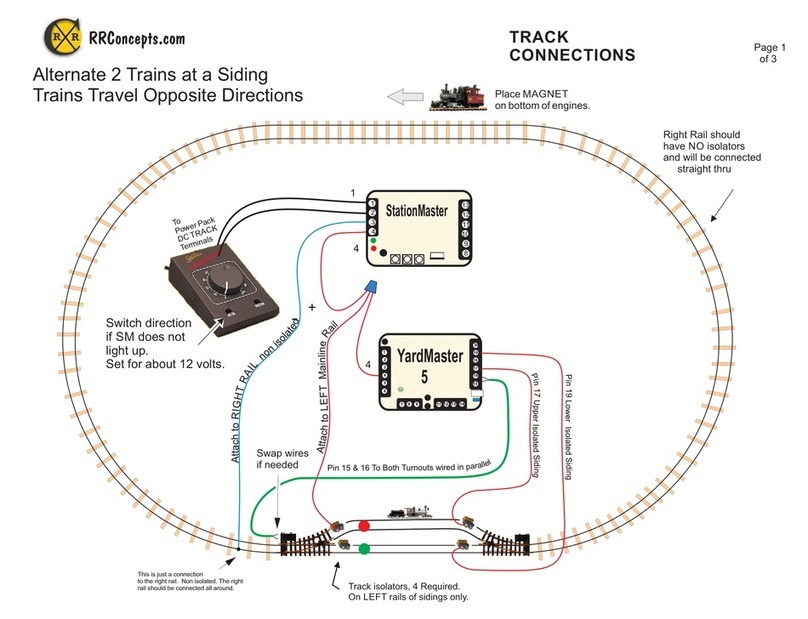
Point to Point Reversing With a Siding
Two trains back-and-forth reversing, alternating.
This hookup does not use sensors and runs
with either the Shuttle or StationMaster set
for reversing mode.
Page 1 of 1
RRConcepts.com
1
2
3
4
8
9
10
11
12
13
StationMaster
or Shuttle
1
1
2
3
4
5
6
20
19
18
17
16
15
711
812
913 14
YardMaster
4
l
a
n
i
m
r
e
T
4
la
n
im
r
e
T
The YardMaster will only fire when the train is going “forward”.
If the turnout switches on the wrong end then swap the wires in StationMaster pins 3 and 4.
See the manual for adding additional in-between stops.
Attach
Data
Cable
StationMaster Programming:
* Reversing mode.
* Fire YardMaster in forward direction only.
Shuttle Programming:
* Set train count to 2.
Isolators with diodes
(3 places)
Swap diode
polarity if train
does not stop.
Isolators
Attach to isolated
rails
The trains will accelerate and decelerate, stopping at the diode
section.
Requires an isolator on each siding, and diodes on each end.
See the StationMaster manual for setting the reversing locations.
The Shuttle will automatically self-adjust.
This rail has no isolators or diodes.

19
+ Voltage INPUT
Common Ground
Output Voltage to Track
Sensor
Inputs
+ 5V
Common Ground
Electrical Details
For reference only
The locations of the common grounds could be useful for some wiring harnesses.
Common Ground
Sensor Input
Common Ground
Sensor Input
Common Ground
Sensor Input
1
2
3
4
8
9
10
11
12
13
tation aster
SM
C
RR
RR Concepts

20
Sensor Placements on Track
The suggested sensor placement on track is shown below with the train magnet installed
in the center of the train. Best sensing is done with the magnet passing over the tip of
the sensor.
Sensor Placement for identifying a train.
Offset the train’s magnet
to the same side as the
sensor as shown.
For example,
passenger trains have the magnet offset to the right and freight trains
have the magnet offset to the left side.
Sensor placement for HO EZ track is under the roadbed.
Other scale trains can place the sensors where appropriate. Very small sensors are available
which do not have the waterproof housing. These smaller sensors can be used for N, HO, etc.
Contact RR Concepts for these sensors.
Your StationMaster is warranted, and guaranteed operational for 1 year.
It will be repaired or replaced at no charge within that time period.
Contact for additional information.http://www.RR-Concepts.com
WARRANTY
C
RR
RR Concepts
Table of contents
Other RR-Concepts Toy manuals
Popular Toy manuals by other brands

Eduard
Eduard P-47D-20 Thunderbolt interior s. adh. manual

REVELL
REVELL Mirage 2000 C Assembly manual

VTech Baby
VTech Baby Drive & Discover Baby Keys Parents' guide

Kyosho
Kyosho Messerschmitt Bf109E 40 instruction manual

REVELL
REVELL F-102A DELTA DAGGER manual

Fisher-Price
Fisher-Price Rescue Heroes C4778 quick start guide