Operation
A. Remove all shipping plugs from the hoses and fittings.
B. Ensure that a suitable element is fitted and that the element
housing cover is fitted with its ‘O’ ring and that the cover is
correctly screwed into place.
Excessive force is not required.
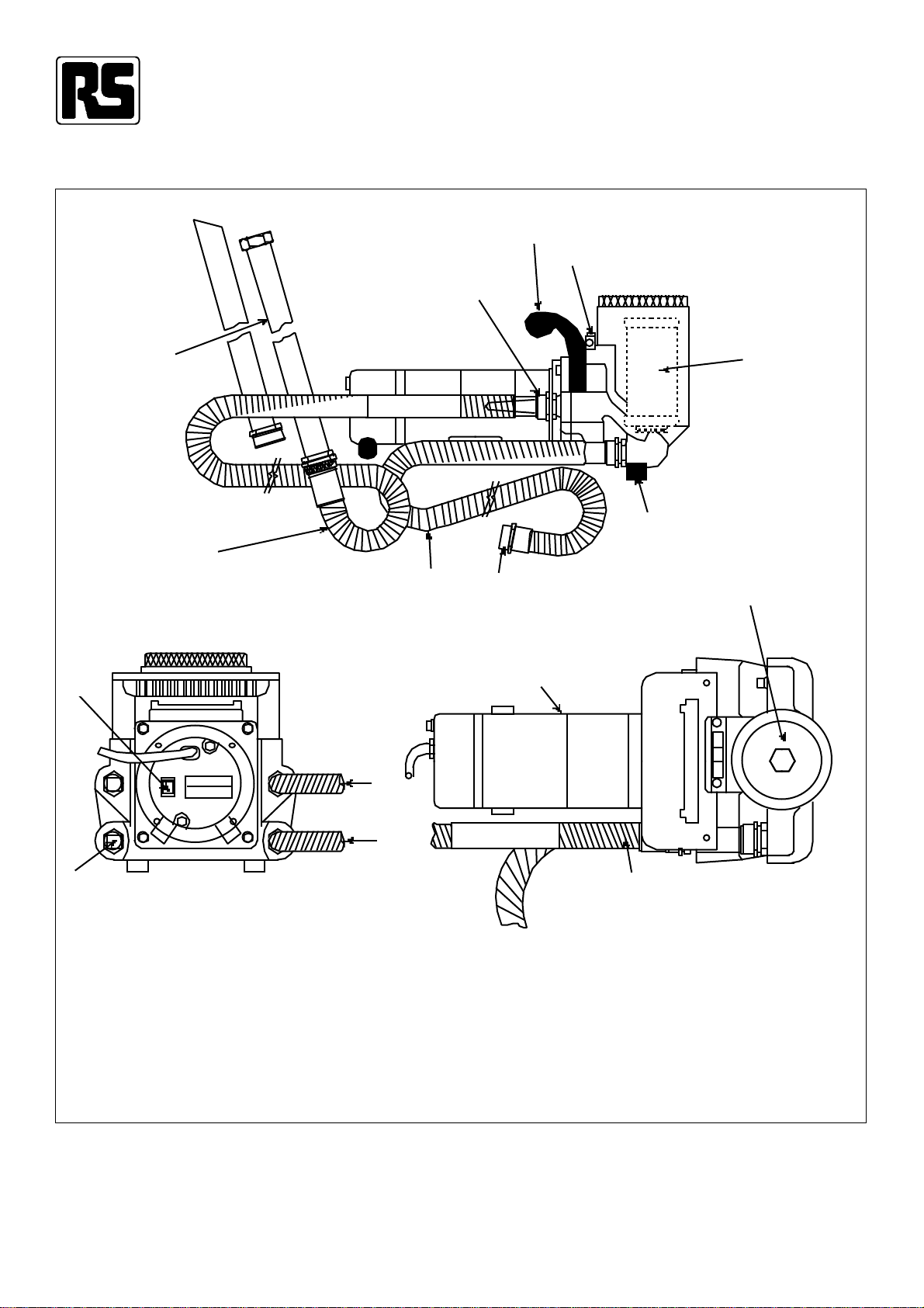
C. Ensure that the hoses are correctly fitted to the filter unit
(see Figure 1).
The inlet, or suction hose should be fitted to the port
nearest to the motor, marked with arrow
The outlet hose should be fitted to the port furthest from the
motor, marked with arrow
D. Connect the wand assemblies if required.
E. Place the inlet hose/wand assembly into the fluid to be
filtered and/or transferred. Place the outlet hose/wand
assembly into a suitable fluid discharge container.
F. Connect the filter unit to the appropriate power supply and
switch on the filter unit utilising the on/off switch at the rear
of the unit (Figure 1).
G. If, during operation the 1.7 bar differential visual indicator
(element condition monitor) Figure 1, moves into the red
area, switch off the unit and change the element. (See
element servicing section).
Please note: That if the filter unit is being used to pump fluid to
a height of more than 2 metres, the indicator may
move into the red area immediately. This is
caused by the extra pressure generated and
does not necessarily indicate that the element
needs changing.
H. Upon completion of the operation, switch the filter unit off
and disconnect from the power supply.
I. Withdraw the hoses from their respective fluid containers
and drain them into a waste fluid vessel. To ensure ‘No-
mess’ transportation, the inlet and outlet hose assemblies
can be screwed together by removing the wand assembly.
Element servicing
A. Switch off the filter unit and isolate from the power supply.
B. Rotate the element housing cover anti-clockwise and
remove.
C. Remove the dirty/contaminated element from the housing
and dispose of. (Elements are non-cleanable). Ensure
element housing is clean.
D. Place the new element in the housing, fitting the ‘O’ ring
seal into the lower location hole.
E. Inspect the housing cover ‘O’ ring and replace if necessary.
F. Replace the housing cover and hand-tighten.
Note: It is recommended the filter unit is cleaned and flushed
between uses.
Technical specification
Maximum allowable
operating pressure 3.5 bar
Flow capacity Up to 15 litres/min
Visual element
condition indicator Differential pressure type set at 1.7
bar
Fluid compatibility Petroleum based and water
emulsions
Integral relief valve Set at 3.5 bar for motor protection
Operating temperatures Filter unit -20°C to +82°C
Hose/wand -4°C to +50°C
Weight 10.6 kg
Electrical motor 1/4 hp at 2500 rpm 3A maximum
110V single phase
50 Hz