RST Milo Fire Table User manual

WARNING:For outdoor use only (domestic)
WARNING: Improper installation, adjustment, alteration, service
or maintenance can cause injury or property damage. Read the
installation, operating, and maintenance instructions thoroughly
before installing or servicing this equipment.
WARNING
Do not store or use gasoline, or other
ammable vapors and liquids, in the
vicinity of this or any other appliance.
A LP-cylinder not connected for use shall
not be stored in the vicinity of this or any
other appliance.
DANGER If you smell gas:
1. Shut o gas to the appliance
2. Extinguish any open ame
3. If odor continues, keep away from
the appliance and immediately call
your gas supplier or re department.
WARNING
Chemicals known to the State of
California to cause cancer, birth defects,
or other reproductive harm are created
by the combustion of propane.
WARNING
Byproducts of the combustion of
propane contain chemicals known to
the State of California to cause cancer
or other reproductive harm.
DANGER CARBON MONOXIDE HAZARD
This appliance can produce carbon monoxide which
has no odor. Using it in an enclosed space can kill you.
Never use this appliance in an enclosed space such as
a camper, tent, car, or home.
36"x 58"
Fire Table

1
36"x 58"Fire Table
ASSEMBLY INSTRUCTIONS
IMPORTANT, RETAIN FOR FUTURE REFERENCE.
READ CAREFULLY.

2
PARTS LIST
NO. PICTURE PART DESCRIPTION QTY.
A Table base 1
B Table top 1
C Burner tray 1
D Buttery bolt (M8) 4
E Table glass shield 4
F Glass connector clips 4
G Glass screws 8
H 10kgs re glass 1
I Burner lid 1
J Lock washer 4
K Spring washer (M8) 4

3
Step 1. TABLE TOP ASSEMBLY - Attach the re table top (B) to the base (A) by
securing with the bolts (D) and the washers (K + J)
Step 2. BURNER TRAY ASSEMBLY - Lower the burner tray (C) into the rectangular
opening in the re table top (B).

4
Step 3.
GLASS WINDSHIELD ASSEMBLY INSTRUCTIONS
1. Pin the glass clips (F) to the location holes on the table top rst.
2. Then, insert one piece of glass (E) to one side of the clips and fasten with screws (G).
3. Insert another piece of glass (E) to the neighbor side of the clips, fasten with the
screws (G) again.
4. Finally, assemble the balance 2 pieces of the glasses in the same way.
Step 4. ADD GLASS MEDIA - Pour glass media (H) into the burner tray. Take care
not to add more than ½ inch of media over the ame element.
WARNING !
Don’t cover the
gas collector cover

5
Step 5. PROPANE TANK ATTACHMENT - Attach the LP hose from the burner tray
to the LP tank (not included). The marked cylinder LPG capacity is 20 lbs. As
stated by the cylinder manufacturers.
Step 6.
PREPARE FOR LIGHTING - Place a AA battery (not included) in the LP
Valve/Starter Panel before trying to ignite.
CAUTION: Before igniting, turn the valve on the LP tank. Apply soap water
onto all of the leaking components. If bubbles appear, tighten it and apply
soap water again. If no bubbles appear, turn o the valve and proceed to
ignite. If there are still bubbles, please contact RST Brands.

6
Step 7.
LIGHTING INSTRUCTIONS - Make sure the propane tank valve is open before
proceeding. Improper lighting procedures may cause potential consequences.
1. To ignite, push the regulator knob forward and turn one quarter turn
counter clockwise to the “low” position.
2. With the valve depressed, push the igniter button to make the pilot
burner re. Once the pilot burner is red, hold down the valve for over
ten seconds to prevent the pilot burner ame from extinguishing, then
release it.
3. To lower the ame once red, turn the valve without pushing it. To
increase the ame, push the valve in and turn it counter clockwise toward
the high re. If the ame is not in a stable condition (making noise, ame
swaying, etc.), please turn it o immediately

7
Step 8.
SHUTTING OFF THE FIRE TABLE - To shut o, close the valve at the
propane tank taking care to ensure the ame is completely extinguished.
Push the regulator valve in and turn to the o position. Allow 5-minutes of
complete shut o before the appliance is reignited.
Step 9. COVER BURNER - Use lid (I) to cover the burner when not in use. Note: the
cover must be removed when the burner is in operation.

8
CARE AND MAINTENANCE
METAL FRAME MAINTENANCE
Furniture incorporates metal frames, which are design to require minimum
maintenance.
• Metal frames should be kept clean.
• Do not let dirt build up on the metal surfaces.
• Cleaning with mild soap and water is all that is required.
• Never leave furniture in standing water.
• To keep your furniture looking it’s best, you may wish to store or cover your
furniture when not in use for an extended period of time.
NATURAL AND FAUX STONE TOPS
All natural stone table tops, including tumbled marble, polished marble and granite,
are treated at the factory with an impregnating sealer that penetrates deep into the
porous surface providing a long lasting barrier that locks out oils, water, stains and
dirt.
• Spills should be wiped up quickly to avoid any staining on the surface. Regular
cleaning with mild soap and water with a sponge or soft scrub brush is all that
is required.
• Regular residential use should not require resealing for at least 2 to 4 years.
• Natural stone tops will fade in direct sunlight over time. This fading is a natural
process and will be more noticeable on brightly colored stones and polished
marble.
• Stone tops may be re-polished professionally, and always require resealing after
polishing.
• Storing or covering your natural stone top when not in use for extended periods
of time is recommended.

9
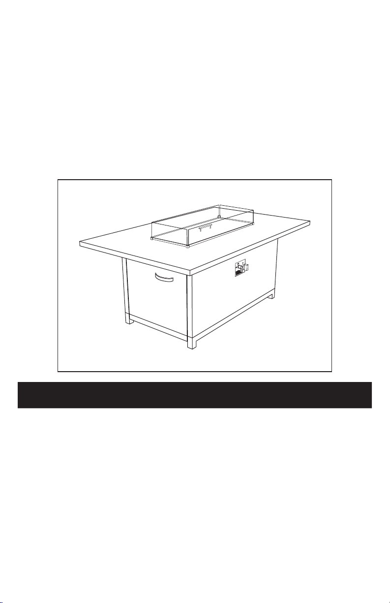
FIRE PIT OWNERS MANUAL
Important: Read these instructions carefully before starting installation of the
outdoor re table.
Operation Checklist
For a safe and pleasurable heating experience, perform this check before each use:
Before operating, conrm:
1. I am familiar with the entire owner’s manual and understand all precautions noted.
2. All components are properly assembled, intact, and operable.
3. No alterations have been made.
4. All gas connections are secure and do not leak.
5. Wind velocity is below 10 mph.
6. Unit will operate at reduced eciency below 40 F/ 4 C
7. Fire pit is outdoors and outside of any enclosure.
8. There is adequate fresh air ventilation. Do not use this appliance is any part has been
under water. Immediately call a qualied service technician to inspect the appliance and to
replace any part of the control system and gas control which has been under water.
9. Fire pit is away from gasoline or other ammable liquids or vapors.
10. Fire pit is away from windows, air intake openings, sprinklers, and other water sources.
11. Fire pit is at least 36 inches on rear and at least 36 inches on sides from combustible
materials.
12. Fire pit is on a hard and level surface.
13. There are no signs of spider or insect nests.
14. All burner passages are clear.
15. All air circulation passages are clear.
Warnings:
1. Children and adults should be alerted to the hazards of high surface temperatures and
should stay away to avoid burns or clothing ignition.
2. Young children should be carefully supervised when they are in the area of the re pit.
3. Clothing or other protective material should not be hung from the re pit, or placed on or
near the re pit.
4. Any guard or protective device removed for servicing the re pit must be replaced prior to
operating the re pit.
5. Installation and repair should be done by a qualied service person. The re pit should be
inspected before use and at least annually by a qualied service person.
6. More frequent cleaning may be required as necessary. It is imperative that control
compartment, burner, and circulating air passageways of the re pit be kept clean.
After operation:
1. Gas control is in the OFF position.
2. Gas tank valve is turned OFF.
3. Disconnect the gas line.
4. After each use, replace the cap on the tank.
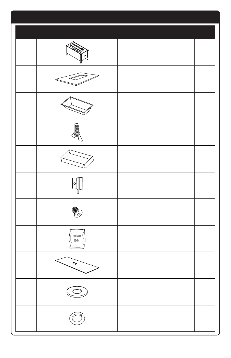
Before beginning assembly, make sure all parts are present. Compare parts with the package
contents list and hardware contents above. If any part is missing or damaged, do not attempt to
assemble the product. Contact customer service for replacement parts.
Important: for safe operation and proper performance of this product and to comply with
certication, listings, and building code acceptances, use only our controls, parts, and accessories
that have been specically listed for use with this burner system. Use of other controls, parts, or
accessories is prohibited and will void all warranties, certications, listings, and building code
approvals, and may cause property damage, personal injury, and loss of life.

10
WARNINGS
Estimated assembly time: 15 minutes
Tools required (not included): Phillips screwdriver with medium blade, and leak detection solution.
Code and supply requirements: the installation of this product must conform with local codes or,
in the absence of local codes, with the latest National Fuel Gas Code,
DANGER If you smell gas:
1. Shut o gas to the appliance
2. Extinguish any open ame
3. If odor continues, keep away from the
appliance and immediately call your gas
supplier or re department.
WARNING
Do not store or use gasoline, or other
ammable vapors and liquids, in the
vicinity of this or any other appliance.
A LP-cylinder not connected for use shall
not be stored in the vicinity of this or any
other appliance.
Installer and Consumer
these instructions MUST be retained with this appliance for future reference. For outdoor use only.
If stored indoors, detach and leave the cylinder outdoors.
Parts List:
1.Fire table
2.Burner Pan ( natural or propane)
3. Control Knob
4. NG orifice and air shutter
5. Fire pan outline border
6. Glass wind guard
2a 2b 3
4 5
6a 6b

11
WARNINGS
PRE-INSTALLATION AND PREPARATION SAFETY GUIDELINES
1. Before installing this unit, check the minimum clearance to combustible section
to ensure that the surrounding area is properly sized for the installation.
2. The unit is for outdoor use only. DO NOT install or use this appliance inside of
a building, garage, or any other enclosed area, including recreational vehicles
and/or boats. This unit must be installed in such a manner that the vent opening
at the base of the unit remains clear and free of all obstructions at all times
during all weather conditions.
3. CHECK GAS TYPE (natural or propane): the gas supply you intend to use may
not be the same as that stated on the unit rating plate as purchased. If the gas
supply is dierent, convert the unit to the gas type you intend to use. See the
CONVERTING TO A DIFFERENT GAS TYPE section. If you are unsure, contact
the dealer for assistance. ONLY MANUAL UNITS ARE CONVERTIBLE.
4. FOR NATURAL GAS: The minimum inlet gas-supply pressure for purposes of
input adjustments is 3.5” water column (w.c.), and the maximum inlet gas-supply
pressure is 10.5”w.c. FOR PROPANE: The minimum inlet gas supply pressure for
purposes of input adjustment is 8” w.c., and the maximum inlet gas supply 13”
w.c. DO NOT INSTALL THIS UNIT IF MINIMUM PRESSURE IS NOT AVAILABLE OR IF
MAXIMUM PRESSURE IS EXCEEDED.
5. Gas piping system must be sized to provide inlet pressure at the maximum ow
rate (BTU/hr). Undue pressure loss will occur if the pipe is too small, or the run is
too long.
6. For installations at elevations above 2,000 ft., contact your local dealer or gas
supplier before installing. Input ratings should be reduced approximately 4% for
each 1,000 ft. above sea level. Refer to the national Fuel Gas Code.
7. The unit and its individual shuto valve must be disconnected from the
gas-supply piping system during any pressure testing of that system at test
pressures in excess of ½ psi (3.5 kPa). This is accomplished by closing the gas
supply line valve. The unit must be isolated from the gas supply piping system
by closing its individual manual shuto valve during any pressure testing of the
gas-supply piping system at test pressures equal to or less than ½ psi (3.5 kPa).
8. INSTALLER NOTE: This unit should be installed so that it can be removed if
service is required.
9. GAS-SUPPLY PLUMBING REQUIREMENTS:
a. Apply only joint compounds that are resistant to all gases on all male pipe
ttings. Make sure to tighten every joint securely. Do not use pipe joint
compound to connect are ttings. Bring the gas-supply pipe up from
beneath the enclosure near its center (if applicable).
Caution: Installation and maintenance must be done by an NFI Certied or other
qualied professional installer. Installer, read these instructions before installing this
product. Be sure you understand all safety precautions and warnings contained in this
manual.
Note: An external on/o valve in the gas line is required for safety when the unit is not in use.
It also provides for convenient maintenance and repair.

12
INSTALLATION SAFTEY GUIDLINES
1. Installation and repair should be done by a qualied service person. The
appliance should be inspected before use and at least annually by a qualied
service person. More frequent cleaning may be required as necessary. It is
imperative that control compartment, burners, and circulating air passageways
of the appliance be kept clean.
2. Carefully inspect for shipping damage. If any parts are damaged, call the dealer.
3. Correct installation and proper placement of the unit and decorative media
is crucial to the safe performance of the unit. See installation instructions for
further information.
4. Ensure that the unit is installed in such a manner that the vent opening at
the base of the unit remains obstacle-free at all times and during all weather
conditions.
5. Due to high temperatures, the unit must be located out of trac areas and
away from combustibles.
OPERATING THE UNIT SAFELY AND CORRECTLY
1. This appliance is only intended for operation in temperatures above 32 F.
2. When shutting the unit down make sure to turn the control valve FULLY OFF.
3. Children MUST be carefully supervised when they are in the area of this
appliance.
4. DO NOT sit or place any part of the body, clothing, or other ammable materials
on or near the unit surrounding. Children and adults should be alerted to the
hazard of high surface temperatures and should stay away to avoid burns or
clothing ignition.
5. Every time you use the unit, make sure that:
a. The area around the unit is clear and free from combustible materials, gasoline,
and other ammable vapors and liquids.
b. There is no blockage of the airow through the vent openings located on the
bottom of the unit.
c. The hose is inspected (if applicable). See the SAFE USE AND MAINTENANCE OF
PROPANE-GAS CYLINDERS section.
6. WARNING: HOT WHILE IN OPERATION AND FOLLOWING OPERATION. Serious
injury can occur! Do NOT throw trash, paper, or other ammable materials in
the unit. DO NOT leave in operation when unattended. DO NOT OPERATE THIS
UNIT IN THE RAIN.
7. SOLID FUEL MUST NOT BE BURNED IN THE UNIT.
8. DO NOT continue using if you smell unusual odors or have headaches, nausea,
or dizziness.
9. DO NOT store any combustible materials, gasoline, and any other ammable
vapors/liquids in the vicinity of this unit. Provide adequate clearance for
servicing and operation.
10. Matches, paper, garbage, or any other material must not be thrown into the
unit or into the ame.
11. DO NOT use the unit if any part of it has been underwater. Immediately call a
qualied professional service technician to inspect the set and to replace any
part of the control system that has been underwater.

13
SAFE USE & MAINTENANCE OF PROPANE GAS BOTTLES
IMPORTANT FOR YOUR SAFETY
READ AND FOLLOW ALL WARNINGS PROVIDED WITH THE PROPANE GAS CYLINDER
When operating this appliance with a propane-gas cylinder, these instructions and warnings MUST be observed.
FAILURE TO DO SO MAY RESULT IN A SERIOUS FIRE OR EXPLOSION.
CYLINDER/ CONNECTOR REQUIREMENTS
1. Propane-gas cylinders, valves, and hoses must
be maintained and in good condition and must
be replaced if there is visible damage to either
the cylinder or valve. If the hose is cut or shows
excessive abrasion or wear, it must be replaced
before using the gas appliance (see 5).
2. This unit, when used with a cylinder, should be
connected to a standard 5-gallon (20 lb.)
propane gas cylinder equipped with an OPD
(Overfill Prevention Device). The OPD has been
required on all cylinders sold since October 1,
1998, to prevent overfilling.
3. Cylinder dimensions should be approximately
12” (30.5) cm in diameter and 18” (45.7 cm)
high. Cylinder must be constructed and marked
in accordance with the Specifications for
Propane Gas Cylinders of the U.S. Department
of Transportation (DOT) or the National
Standard of Canada, Cylinders, Spheres, and
Tubes for Transportation of Dangerous Goods.
4. The cylinder used must include a collar to
protect the cylinder valve, and the cylinder
supply must be arranged for vapor withdrawal.
5. The pressure regulator and hose assembly
(figure 7-1) supplied with this outdoor cooking
gas appliance must be used. Original and
replacement pressure regulator and hose
assemblies must be those specified by the
manufacturer for connection with a cylinder
connecting device identified as Type.
6. The propane gas cylinder valve must be
equipped with a cylinder connection coupling
device, described as Type I in the standard
defined in no. 5 above. This device is commonly
described as an Acme thread quick coupler.
7. If the propane gas cylinder comes with a dust
plug, place the dust cap on the cylinder valve
outlet whenever the cylinder is not in use.
QUICK COUPLER OPERATION
To connect the regulator/hose assembly to the
propane-gas cylinder valve tting: Press the hand
nut on the regulator over the Acme thread tting
on the cylinder valve. Turn the hand nut clockwise
to engage the threads and tighten until snug.
The use of pliers or a wrench should not be
necessary. Only cylinders marked “propane” may
be used.
To disconnect: Turn the hand-nut
counterclockwise until detached (Fig. 7.1).
Important: Before using the unit, and after each
time the cylinder is removed and reattached,
check the hose for wear (see no. 1) and check
all connections for leaks. Turn o the unit valves
and open the main cylinder valve, then check
connections with the soapy water. Repair any
leaks before lighting the unit.
CAUTION: Always turn the propane cylinder main
valve o after each use, and before moving the
unit and cylinder or disconnecting the coupling.
This valve must remain closed and the cylinder
disconnected while the appliance is not in use,
even though the gas ow is stopped by a safety
feature when the coupler is disconnected.
Carefully inspect the hose assembly each time
before the gas is turned on. A cracked or frayed
hose should be replaced immediately.
If the appliance is stored indoors, the
cylinder must be disconnected and removed.
Disconnected cylinders must be stored outdoors,
out of the reach of children, with threaded valve
plugs tightly installed, and must not be stored in
a building, garage, or any other enclosed area.
FOR YOUR SAFETY
1. DO NOT store a spare propane-gas cylinder
under or near this appliance.
2. NEVER ll the cylinder beyond 80-percent
full.
3. IF THE INFORMATION IN NO.1 AND NO.2 IS
NOT FOLLOWED EXACTLY, A FIRE CAUSING
DEATH OR SERIOUS INJURY MAY OCCUR.
FIG. 71

14
IMPORTANT SAFTEY INFORMATION
BE CAREFUL
If not installed and used correctly per these instructions,
this product can cause serious injury.
CAUTION: Installation and maintenance must be done by an NFI Certied or other qualied professional
installer. Read these instructions before installing this outdoor re table. Be sure you understand all safety
precautions and warnings contained in this manual.
1. FOR OUTDOOR USE ONLY. THIS UNIT MUST BE INSTALLED AT LEAST 36” FROM ANY
COMBUSTIBLE WALLS OR MATERIAL. IT MUST NOT BE INSTALLED UNDER ANY TYPE OF CEILING
OR OVERHANG. (see Fig. 9.1)
2. When shutting the unit down—be sure to TURN THE CONTROL VALVE FULLY OFF.
3. WARNING: CARBON MONOXIDE POISONING MAY LEAD TO DEATH. DO NOT MODIFY THIS
OUTDOOR FIREPIT OR ITS CONTROLS, EXCEPT AS PROVIDED FOR IN THIS MANUAL. Any other
change may be dangerous. Improper installation or use of the outdoor repit can cause serious
injury or death from re, burns, explosions, or carbon monoxide poisoning.
4. Check state and local codes to determine if the outdoor re pit is permitted in your locality
before installation.
MINIMUM CLEARANCE TO COMBUSTIBLES
FIG. 91 Note: Nothing should be
above the re pit
36" clearance
From sides to
any combustible
constructions
36" clearance
From sides to
any combustible
constructions
Minimum Clearance to Combustible Construction:
NOTE: NOTHING SHOULD BE ABOVE THE FIRE PIT
36” clearance between sides to any combustible
construction
Clearance to combustible construction:
Side walls: 36” from edge of top ring (Figure 9.1)
Ceiling: Nothing should be above the re pit.
Flooring: 0”- can be installed on deck, slab, oor, etc.
The dimensions shown in Fig. 9.1 are MINIMUM CLEARANCES to maintain when you install this outdoor re pit.
ALL SIDES of the enclosure opening must be AT LEAST 36” from any combustible side walls. The unit MUST NOT
BE installed under any type of ceiling or overhang.
INSTALLATION
Important: Be sure you have read and understand all safety precautions and warnings contained
in this manual.
BEFORE PROCEEDING, CAREFULLY READ ALL OF THE IMPORTANT SAFETY INFORMATION
CONTAINED IN THIS OWNER’S MANUAL, INCLUDING:
A. Pre-installation and preparation safety guidelines
B. Installation and safety guidelines
C. Minimum clearance combustibles.
BE SURE THE GAS SUPPLY FOR THE UNIT IS TURNED OFF.
Note: when installing the unit to natural gas or household propane, you must have a gas-supply
line that has been installed by a qualied professional technician in accordance with all local codes.
Refer to the PARTS LIST when installing the unit.
LOCATION
While following all requirements and safety information in this manual, locate the unit on a at, level
surface.
CONNECT TO A PROPANE CYLINDER GAS SUPPLY
Important: Before installation, be sure the propane cylinder is turned o.

15
vINSTALLATION (CONT.)
Install the regulator hose assembly (not supplied)
to the unit using a gas pipe sealing compound or
Teon Tape. Then attach the regulator end to the
propane cylinder and tighten (see Fig. 10.1). Follow
all instructions and safety warnings supplied with the
propane cylinder.
Place the cylinder in the tank seat, and rotate the
screw clockwise to a full stop (see Fig. 10.2)
CONNECT TO A NATURAL OR HOUSEHOLD
PROPANE GAS SUPPLY
1. Connect a ex connector (not supplied) to the
unit using a gas pipe sealing compound or
Teon Tape (see Fig. 10.3).
2. Bring the gas-supply pipe up from beneath
the unit near its center.
NOTE: Locate the gas supply line out of pathways
where people may trip over it or in areas where the
line may be subject to accidental damage.
3. Install a are adapter (not supplied) to the
gas supply (NPT - using a gas pipe sealing
compound or Teon Tape (see Fig. 10.3).
4. Connect the ex connector to the are adapter
(see Fig. 10.3)
LEAK TEST
Turn on the gas supply, ignite the burner, and test at
all connections for leaks using a soapy water solution.
If bubbles appear, a leak is present. Turn o the gas
and tighten at all connections. Repeat until no leaks
are present. If a leak persists, turn o the gas supply
and contact the local gas company or dealer. NEVER
USE A FLAME TO CHECK FOR LEAKS.
*The gas hose connector shall have a connector that
complies with the Standard for Gas Hose Connectors
for Portable Outdoor Gas-Fired Appliances.
Flex connector (coming from unit)/ flare adapter/ gas
supply/ propane cylinder/ regulator hose (coming
from unit)
FIG. 101
Regulator hose
(from unit)
Propane
cylinder
FIG. 102
FIG. 103
Flex connector
(from unit)
Flare adaptor
Gas supply

16
CONVERTING TO A DIFFERNT GAS TYPE
To convert from propane to natural gas or from natural to propane gas, carefully follow the steps below:
1. SHUT OFF THE GAS SUPPLY TO THE UNIT AND ANY NEARBY ELECTRICAL SOURCES
OR APPLIANCES.
2. If present, remove all decorative media from the unit.
3. Remove the screws attaching the burner pan to your enclosure.
4. Carefully detach the ex connector attached to the orice holder (see Fig. 11.3) and
unscrew the orice holder from the burner pipe (see Fig. 11.4)
5. Remove the orice from the holder (see Fig. 11.4) and replace with the proper-sized one
for your gas requirement. Propane gas requires a 2.30mm (drill size) orice. Natural gas
requires a 3.78mm orice.
Note: if you are converting to and using natural gas you MUST install the air shutter over
burner pipe to cover the air holes (see Fig. 11.4). For propane (L.P.) gas, remove the air
shutter. Replace the orice holder and reattach the connector from the valve (see Fig. 11.3).
The regulator must now be converted to the new gas type.
6. To convert the regulator from propane gas to natural gas, the appliance must be
isolated from the gas supply piping system by closing. It’s individual manual shut o
valve ensuring any pressure testing of the gas supply piping system. At test pressure
equal to or less than ½ psi (3.5 Kpa).
7. Move the propane pipe from the regulator (see Fig. 11.5) and replace with 3/8” natural
gas pipe (see Fig. 11.6, natural gas pipe package not included).
8. Restore your gas supply and check for leaks per the INSTALLATION section. When no
leaks are detected, fasten the burner pan back into place on the enclosure and replace
the decorative media.
FIG. 113
Connector from valve attached to
orice holder on burner pipe
FIG. 115
Remove propane pipe
FIG. 114
ORIFICE
(Remove to change to a dierent gas type)
Burner pipe
2.30mm-propane gas
3.78mm-natural gas
Air shutter (used only with
natural gas. Removed for
propane gas.)
Install gas pipe.
FIG. 116
GLASS WINDSHIELD ASSEMBLY INSTRUCTION remark: applicable models: ULC-FRC58-A-E Series)
1. Pin the glass clips to the location holes on the table top rst.
2. Then, insert one piece of glass to one side of the clips and fasten with the screws.
3. Insert another piece of glass to the neighbor side of the clips, and fasten with the screws again.
4. Finally, assemble the balance 2 pieces of the glasses in the same way.

17
LAVA GRANULE & GLASS CRYSTAL INSTALLATION GUIDELINES
WARNING !
Don’t cover the
gas collector cover
1. Carefully inspect the carton for shipping damage. If any parts are missing or damaged, call the
manufacturer. Do not attempt to install the appliance unless all parts are in good condition.
2. Correct installation is crucial to safe performance of your Outdoor Fire Pit.
3. Due to high temperatures, the Fire Pit must be located out of trac areas and away from
combustibles.
Bag of Lava Rock or Glass Crystals weight: 22 lbs
LAVA GRANULE & GLASS CRYSTAL PLACEMENT
CAUTION: Cuts may occur from the sharp edges on glass. Use safety gloves
during the placement of glass.
Pour the bag of lava granules or glass crystals into the Outdoor Fire Pit so that the burner is
completely covered (see gures 1 and 2). These instructions apply to both round and rectangular
burners.
Top View
FIG. 1 FIG. 2
CAUTION: BURN HAZARD. LAVA GRANULES AND GLASS CRYSTALS WILL
REMAIN HOT FOR SOME TIME AFTER USE.
YOU MUST MAINTAIN THE LAYOUT AS SHOWN TO ENSURE PROPER OPERATION OF
YOUR FIRE PIT. IF YOU NEED TO REPOSITION ANY MATERIAL TO MAINTAIN THE PROPER
LAYOUT, USE HEAT RESISTANT GLOVES OR ALLOW MATERIAL ADEQUATE TIME TO COOL
BEFORE HANDLING.

18
OPERATING THE UNIT-LIGHTING AND EXTINGUISHING
FOR YOUR SAFETY, READ BEFORE LIGHTING
WARNING: IF YOU DO NOT FOLLOW THESE INSTRUCTIONS EXACTLY, A FIRE OR
EXPLOSION MAY RESULT, CAUSING PROPERTY DAMAGE, PERSONAL INJURY, OR
LOSS OF LIFE.
1. BEFORE LIGHTING, smell around the unit area for gas. Be sure to smell next to
the oor, because some gas is heavier than air and will settle on the oor.
2. WHAT TO DO IF YOU SMELL GAS
a. Shut o the gas to the appliance
b. Extinguish any open ame
c. If odor continues, immediately call your gas supplier or the re department.
3. Use only your hand to push in or turn by hand, DO NOT try to repair it. Call a
qualied professional service technician. Force or attempted repair may result in
re or explosion.
MANUAL (MATCH) LIGHTING INSTRUCTIONS
1. STOP! Read the safety information
above.
2. Lay a lighted long-stem match on the
surface of the decorative media near
the burner ring (do not hold the match
in your hand) (see Fig. 15.1) or use a
lighted long-neck butane lighter.
3. Push and slowly turn the control knob
to the ON position (see Fig. 15.3). Your
burner should light.
4. Observe the ame height when lit.
Flame should be 3-13 inches high (see
Fig. 15.4).
5. If the burner does not light before the
match goes out, immediately turn the
control knob to the OFF position.
6. Wait approximately ve minutes to clear
out any gas, and repeat steps 1-4 above.
7. If your burner fails to light again, turn
the control knob to the OFF position
and contact your dealer or gas supplier.
8. To extinguish your gas burner, turn the
control knob to the OFF position. Be
sure the control knob is turned fully o
to avoid any gas leakage.

19
OPERATION
Each installation site for any unit presents its own unique combustion environment. Specic factors
such as weather, wind currents, yard debris, altitude, drafts, the size of the surrounding area, all have
an inuence on the proper operation of the unit. A normally operating unit will demonstrate the
following characteristics:
• A lively, realistic ame
• That is odor-free
If the ame is not clean (identiable by excessive sooting on the decorative media), refer to the
CLEANING AND MAINTENANCE section below.
BATTERIES
• Always purchase the correct size and grade of battery most suitable for the intended use.
• Clean the battery contacts and those of the device prior to battery installation.
• Ensure the batteries are installed correctly with regard to polarity (+ and -)
• Remove batteries from equipment when it is not to be used for an extended period of time.
• Remove used batteries promptly.
CLEANING AND MAINTENANCE
1. Always shut o the gas to the unit while performing service work.
2. Allow the unit to cool before servicing.
3. The unit should be inspected regularly. Excessive debris can build up on this unit from leaves,
dirt, or other debris. It is critical that all control components, burners, and the surrounding
area be kept clean and free of all obstructions.
4. KEEP THE SURROUNDING AREA AT THE BASE OF THE UNIT CLEAN AND FREE OF
OBSTRUCTIONS AT ALL TIMES.
5. The burner assembly must be replaced prior to the unit being put into operation if it is
evident that the burner is damaged. Contact your local dealer for replacement parts.
6. Periodically perform visual checks of the burner ames. The burner ames should be blue at
the base with a combination of blue/yellow at the body and tips. Contact a qualied service
person for maintenance.
CAUTION: HOT DURING OPERATION AND AFTER USE. Children must be supervised when in the
vicinity of this appliance. Serious injury may occur! Children must be alerted to the hazard of high
surface temperatures and should stay away to avoid burns or clothing ignition.
Keep entire area (around bottom) clear for proper vetting.
QUALITY CHECK
Date:
Model #:
Serial #:
Inspector #:
Table of contents
Other RST Outdoor Fireplace manuals
Popular Outdoor Fireplace manuals by other brands

Bond
Bond Cedar Ridge HYFP40205-132 owner's manual

Outdoor GreatRoom Company
Outdoor GreatRoom Company Crystal Fire CF-20-LP user manual

Uniflame
Uniflame 73138 Assembly instructions

Blumfeldt
Blumfeldt Arizona Rust manual

Lava Heat
Lava Heat Lorenzo owner's manual

Empire
Empire OL48TP10N-1 Installation instructions and owner's manual

Afterglow
Afterglow FW-CTGSQFP manual

Planika
Planika Lotus instruction manual

Grand Canyon Gas Logs
Grand Canyon Gas Logs FB3913 Installation & operation manual

tepro
tepro GLADSTONE instruction manual

Jaclyn Smith
Jaclyn Smith FP-K14 owner's manual

Landmann
Landmann FB-V-275 Assembly and operating instructions