RSTEEL RVL-N Single User manual

THE
STRONGEST
IN FINLAND
Technical
Manual
Technical changes and
errors reserved
Design according to ACI and Eurocodes
Version 16.5.2014
RVL-N Single
Wire Loop Box

2
www.repo.eu Technical Manual - RVL-N Single Wire Loop Box v16.5.2014
1 DESCRIPTION OF THE SYSTEM 3
2 DIMENSIONS AND MATERIALS 4
2.1 Dimensions and tolerances 4
2.2 Materials and standards 5
3 MANUFACTURING 5
3.1 Manufacturing method 5
3.2 Manufacturing markings 5
3.3 Quality control 5
4 RESISTANCES ACCORDING TO ACI 6
4.1 Calculation principles 6
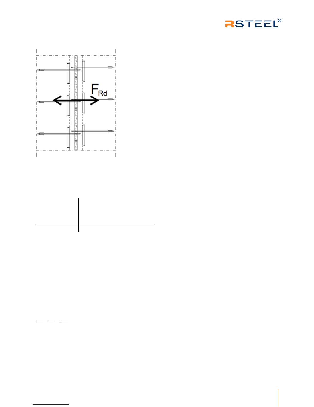
4.2 Design values of resistance for longitudinal shear force (ACI) 6
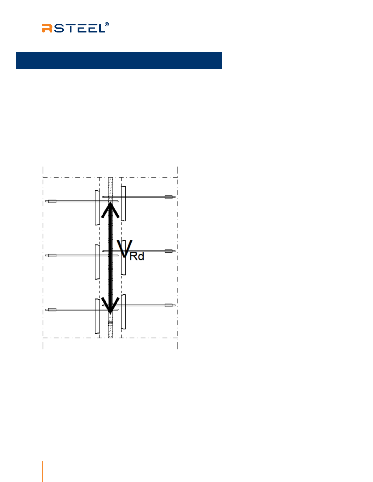
4.3 Design values of resistance for transversal shear force (ACI) 8
4.4 Design value for tensile force (ACI) 9
4.5 Resistances for combined forces (ACI) 9
5 RESISTANCES ACCORDING TO EC 10
5.1 Calculation principles 10
5.2 Design values of resistance for longitudinal shear force (EC) 10
5.3 Design values of resistance for transversal shear force (EC) 12
5.4 Design value for tensile force (EC) 13
5.5 Resistances for combined forces (EC) 13
6 APPLICATION 14
6.1 Limitations for application 14
6.1.1 Minimum edge and center distances 14
6.2 Reinforcement of the concrete 15
6.2.1 Reinforcement of the joint 15
6.2.2 Reinforcement of the concrete element 16
7 INSTALLATION 18
7.1 Attachment to formwork 18
8 SUPERVISION OF INSTALLATION 18
8.1 Installing the RVL wire rope loops 18
Table of Content

3
Technical Manual - RVL-N Single Wire Loop Box v16.5.2014www.repo.eu
RVL wire rope loops manufactured by R-Group Finland Oy are steel parts consisting of a high
strength steel wire and a steel box. RVL wire rope loops are installed to concrete elements before
casting.
When the joint between concrete wall elements is loaded, the longitudinal shear force in the joint
is divided to an angled compression component and a horizontal pull component at the indented
joint. RVL wire rope loop transfers the shear forces acting in the joint between concrete wall ele-
ments by the pull component of the wire rope and the compression component formed by the steel
boxes and the joint
1 DescRiptioN oF tHe sYsteM
RVL wire rope loops manufactured by R-Group Finland Oy are steel parts
consisting of a high strength steel wire and a steel box. RVL wire rope loops are
installed to concrete elements before casting.
When the joint between concrete wall elements is loaded, the longitudinal
shear force in the joint is divided to an angled compression component and a
horizontal pull component at the indented joint. RVL wire rope loop transfers
the shear forces acting in the joint between concrete wall elements by the pull
component of the wire rope and the compression component formed by the
steel boxes and the joint
3
1. Description of the system

4
www.repo.eu Technical Manual - RVL-N Single Wire Loop Box v16.5.2014
2 DiMeNsioNs AND MAteRiALs
4
Wire rope loop SL L L1 h b t Ø D
[mm] [mm] [mm] [mm] [mm] [mm] [mm] [mm]
±10 ±20 ±10 ±2 ±2 ±2 1)
RVL- 60N 60 236 170 160 36 20 5 40
RVL- 80N 80 256 170 160 36 20 5 45
RVL- 140N 140 310 170 160 36 20 5 50
1) according to SFS-EN 12385.
Thickness of the steel plate of the box is 0,5 mm.
2.1 dImEnsIons And tolErAnCEs
PICTURE 1 | Dimensions of the RVL wire rope loop
tAblE 1 | DiMeNsioNs aND toLeRaNces oF tHe RVL wiRe Rope Loop
2. Dimensions and Materials

5
Technical Manual - RVL-N Single Wire Loop Box v16.5.2014www.repo.eu
5
Part Material Standard
Steel box 1.0330 SFS-EN 10130
Wire rope high strength steel wire rope SE-Zn SFS-EN 12385
Compression sleeve 1.0046 SFS-EN 10025
The steel box and the wire rope are zinc coated. Zinced products are
passivated with min. 1 month of storage.
The steel is box is mechanically cut and bent to shape. The open wire rope is installed to the
steel box and attached by the compression sleeve to form a loop. The wire rope is bent in to
the steel box and the open part of the steel box is closed by tape to protect from casting concrete.
Product package is equipped with a R-Steel –sticker, which contains the following information:
product type, product name, quantity, ISO9001 and ISO14001 quality and environment system
markings, FI marking and product picture.
Products are delivered in cardboard boxes on a truck palette. Cardboard boxes are marked with
FI logo, numbers of the ISO-certificates and the product type and name.
Quality control of the wire rope loops is done according to the requirements of the Finnish
Code of Building Regulations and the instructions according to the quality and environment
system of the R-Group Finland Oy (ISO9001 and ISO 14001). R-Group Finland Oy has a quality
control contract with Inspecta Sertifiointi Oy.
3 MaNUFactURiNg
2.2 mAtErIAls And stAndArds
3.1 mAnufACturIng mEthod
3.2 mAnufACturIng mArkIngs
3.3 QuAlIty Control
3. Manufacturing

6
www.repo.eu Technical Manual - RVL-N Single Wire Loop Box v16.5.2014
4. Resistances According to ACI
Design value of resistance VRd for one pair (one wire rope loop on each side of the joint) is
presented in table 2. The minimum concrete strength in the joint (element/joint concrete) is
C25/30 (cylinder strength 25 MPa, cube strength 30 MPa). Distance between wire rope loop pairs
must be according to section 6.1.1.
6
The longitudinal shear capacities of the RVL wire rope loops are calculated according to
Building Code Requirements for Structural Concrete (ACI 318M-08).
Capacities are calculated for static loads. The calculations do not take into account cracks or
deformations in the joint.
4 ResistaNces accoRDiNg to aci
4.2 dEsIgn vAluEs of rEsIstAnCE for longItudInAl
shEAr forCE (ACI)
4.1 CAlCulAtIon prInCIplEs
PICTURE 2 | Direction of longitudinal shear force in joint

7
Technical Manual - RVL-N Single Wire Loop Box v16.5.2014www.repo.eu
Wire rope loop Design value for shear force in one pair
of wire rope loops (one wire rope loop on
each side of the joint) VRd [kN]
RVL-60N 11.7
RVL-80N 11.7
RVL-100N 11.1
RVL-120N 9.6
RVL-140N 8.5
Design values of resistance presented in the table 3 are resistances in ultimate limit state with given
center to center distances of RVL wire rope loop boxes. Values are given as kN/m. The minimum concrete
strength in the joint (element/joint concrete) is C25/30 (cylinder strength 25 MPa, cube strength 30 MPa).
Vrd [kN/m]
c/c
[mm] RVL-60N RVL-80N RVL-100N RVL-120N RVL-140N
250 46.8 46.8 44.3 38.4 33.9
300 39.0 39.0 36.9 32.0 28.2
350 33.4 33.4 31.6 27.4 24.2
400 29.3 29.3 27.7 24.0 21.2
450 26.0 26.0 24.6 21.3 18.8
500 23.4 23.4 22.2 19.2 16.9
550 21.3 21.3 20.1 17.5 15.4
600 19.5 19.5 18.5 16.0 14.1
650 18.0 18.0 17.0 14.8 13.0
700 16.7 16.7 15.8 13.7 12.1
750 15.6 15.6 14.8 12.8 11.3
7
tAblE 2 | DesigN VaLUe oF ResistaNce FoR LoNgitUDiNaL sHeaR
FoRce iN oNe paiR oF wiRe Rope Loops
tAblE 3 | DesigN VaLUes oF ResistaNce FoR LoNgitUDiNaL sHeaR
FoRce FoR wiRe Rope Loops

8
www.repo.eu Technical Manual - RVL-N Single Wire Loop Box v16.5.2014
Design value of resistance for transversal shear force NRd presented in table 4 is resistance in ultima-
te limit state. The minimum concrete strength in the joint (element/joint concrete) is C25/30 (cylinder
strength 25 MPa, cube strength 30 MPa).
Design values for transversal shear force apply for one pair of RVL wire rope loops (one wire rope loop
on each side of the joint). Distance between wire rope loop pairs must be according to section 6.1.1.
bs
[mm]
NRd
[kN]
≥ 70 3,1
8
4.3 dEsIgn vAluEs of rEsIstAnCE for trAnsvErsAl
shEAr forCE (ACI)
PICTURE 3 | Direction of transversal shear force
tAblE 4 | DesigN VaLUes oF ResistaNce FoR tRaNsVeRsaL sHeaR
FoRce FoR wiRe Rope Loops (oNe wiRe Rope Loop oN eacH siDe
oF tHe joiNt)

9
Technical Manual - RVL-N Single Wire Loop Box v16.5.2014www.repo.eu
Design values for transversal shear force apply for one pair of RVL wire rope loops (one
wire rope loop on each side of the joint). Distance between wire rope loop pairs must be
according to section 6.1.1. The minimum concrete strength in the joint (element/joint
concrete) is C25/30 (cylinder strength 25 MPa, cube strength 30 MPa).
Wire rope loop
Design value for tensile force in one
pair of wire rope loops (one wire
rope loop on each side of the joint)
FRd [kN]
RVL-60N … 140N 4.2
Resistance of RVL wire rope loop joint for combined forces
may be calculated according to equation
in which
VEd = design value of longitudinal shear force
VRd = design value of resistance for longitudinal shear force
NEd = design value of transversal shear force
NRd = design value of resistance for transversal shear force
FEd = design value for tensile force
FRd = design value of resistance for tensile force
VEd NEd FEd
VRd NRd FRd
++≤1
9
4.4 dEsIgn vAluE for tEnsIlE forCE (ACI)
PICTURE 4 | Direction of tensile force
tAblE 5 | DesigN VaLUe FoR teNsiLe FoRce iN oNe paiR oF
wiRe Rope Loops
4.5 rEsIstAnCEs for CombInEd forCEs (ACI)

10
www.repo.eu Technical Manual - RVL-N Single Wire Loop Box v16.5.2014
Capacities are calculated for static loads. The calculations do not take into
account cracks or deformations in the joint.
5 ResistaNces
accoRDiNg to ec
Design values of resistance presented in the tables are resistances in ultimate limit state.
The resistance is defined by the weakest concrete in the joint (element/joint concrete).
10
5.1 CAlCulAtIon prInCIplEs
The longitudinal shear capacities of the RVL wire rope loops are calculated
according to Eurocode EN 1992-1-1 chapter 6.2.5.
5.2 dEsIgn vAluEs of rEsIstAnCE for
longItudInAl shEAr forCE (EC)
PICTURE 5 | Direction of longitudinal shear force in joint
5. Resistances According to EC

11
Technical Manual - RVL-N Single Wire Loop Box v16.5.2014www.repo.eu
c/c
[mm]
VRd [kN/m]
C25/30 C30/37 C35/45 C40/50
250 54 55 57 58
300 47 48 49 50
350 41 42 43 44
400 37 38 39 40
450 34 35 36 37
500 31 33 34 35
550 29 31 32 33
600 28 29 30 31
650 26 27 28 29
700 25 26 27 28
750 24 25 26 27
11
tAblE 6 | DesigN VaLUes oF ResistaNce FoR LoNgitUDiNaL
sHeaR FoRce FoR wiRe Rope Loop RVL 60-N

12
www.repo.eu Technical Manual - RVL-N Single Wire Loop Box v16.5.2014
Design values of resistance presented in the tables are resistances in ultimate limit state. The resistance is defined
by the weakest concrete in the joint (element/joint concrete).
Design values for transversal shear force apply for one pair of RVL wire rope loops (one wire rope loop on each side
of the joint). Distance between wire rope loop pairs must be according to section 6.1.1.
bs
[mm]
NRd [kN]
C25/30 C30/37 C35/45 C40/50
≥ 70 2.6 2.8 3.0 3.2
12
5.3 dEsIgn vAluEs of rEsIstAnCE for
trAnsvErsAl shEAr forCE (EC)
tAblE 7 | DesigN VaLUes oF ResistaNce FoR tRaNsVeRsaL sHeaR FoRce FoR
wiRe Rope Loop RVL 60-N (oNe wiRe Rope Loop oN eacH siDe oF tHe joiNt)
PICTURE 6. | Direction of transversal shear force

13
Technical Manual - RVL-N Single Wire Loop Box v16.5.2014www.repo.eu
Design values for transversal shear force apply for one pair of RVL wire rope loops (one wire rope loop on each side
of the joint). Distance between wire rope loop pairs must be according to section 6.1.1.
Wire rope loop Design value for tensile force in one
pair of wire rope loops (one wire
rope loop on each side of the joint)
FRd [kN]
RVL 60-N 4,2
Resistance of RVL wire rope loop joint for combined forces may be calculated according to equation
in which
VEd = design value of longitudinal shear force
VRd = design value of resistance for longitudinal shear force
NEd = design value of transversal shear force
NRd = design value of resistance for transversal shear force
FEd = design value for tensile force
FRd = design value of resistance for tensile force
VEd NEd FEd
VRd NRd FRd
++≤ 1
13
5.4 dEsIgn vAluE for tEnsIlE forCE (EC)
PICTURE 7 | Direction of tensile force
tAblE 8 | DesigN VaLUe FoR teNsiLe FoRce iN oNe paiR oF wiRe Rope Loops
5.5 rEsIstAnCEs for CombInEd forCEs (EC)

14
www.repo.eu Technical Manual - RVL-N Single Wire Loop Box v16.5.2014
6.1.1 MiNiMUM eDge aND ceNteR Di sta Nces
Center to center Emin = minimum distance between wire rope loops at the
same side of the joint.
Edge distance Dmin = the minimum distance of the wire rope loop to the
upper and lower edge of the concrete element.
Center to center Cmax = minimum distance between wire rope loops at
opposite sides of the joint.
Minimum width Bmin = minimum total wall width.
Wire rope loop center to center
Emin [mm]
edge distance
Dmin [mm]
center to center
Cmax [mm]
minimum width
Bmin [mm]
RVL 60-N 250 100 20 70
Resistances presented in tables 2…8 are calculated for static loads. RVL wire rope loops
are not designed to be used for liing or as liing loops.
Resistance of the RVL wire rope loop is defined by the weakest concrete in the joint
(element/joint concrete). The resistance calculations do not take into account cracks or
deformations in the joint. In resistance calculations it is assumed that the steel boxes
and the seam are fully filled with concrete.
6 appLicatioN
6.1 lImItAtIons for ApplICAtIon
PICTURE 8 | Markings for distances of the RVL wire rope loops
tAblE 9 | MiNiMUM DistaNces oF RVL wiRe Rope Loops
6. Application

15
Technical Manual - RVL-N Single Wire Loop Box v16.5.2014www.repo.eu
The size of the wire rope loops must be chosen according to the thickness of the joint to enable the vertical ribbed
steel bar in the joint to pass through the wire rope loops on both sides of the joint.
The total wall width of the concrete wall element must be chosen taking into account the width of the indented
joint, the width of the steel box of the wire rope loop (table 1) and the required concrete cover.
Recommended thicknesses of the seam
The recommended thicknesses of the seam are according to table 9 and picture 9.
Wire rope loop Recommended
thickness of the
seam b [mm]
RVL 60-N 70…90
Wire rope loop Diameter of the
ribbed steel bar
Øs [mm]
RVL 60-N 12
6.2.1 ReiNFoRceMeNt oF tHe joiNt
When using the RVL wire rope loops, a vertical ribbed steel bar must always be
installed to the joint according to picture 10. This ribbed steel bar is installed
through the wire rope loops according to picture 10.
PICTURE 9 | Thickness of the seam b
tAblE 10 | RecoMMeNDeD tHickNesses oF tHe seaM b
6.2 rEInforCEmEnt of thE ConCrEtE
tAblE 11 | size oF tHe
RibbeD steeL baR iN tHe
joiNt, steeL a500Hw oR
siMiLaR
PICTURE 10 | Ribbed steel bar in the joint

16
www.repo.eu Technical Manual - RVL-N Single Wire Loop Box v16.5.2014
6.2.2 ReiNFoRceMeNt oF tHe coNcRete eLeMeNt
The wall elements must be reinforced according to the wall element design.
1) When RVL wire rope loops are used to transfer forces
When RVL wire rope loops are used to transfer forces in the joint, anchorage of the wire rope
loop must be secured by overlapping the wire rope loop suciently with the reinforcement of
the concrete element. For wire rope loops RVL 60-N the greatest design value for tensile force is
FRd = 15 kN. The anchorage of the wire rope loops must be designed for these forces when using
design values for resistances presented in tables 2…8.
16
PICTURE 11 | Example of element edge reinforcement when transferring forces

17
Technical Manual - RVL-N Single Wire Loop Box v16.5.2014www.repo.eu
2) When RVL wire rope loops are not used to transfer forces
When RVL wire rope loops are used to limit cracking of the seam or to tie elements together without defining the
required force edge reinforcement of the element may be done according to principles presented in picture 12.
Edge reinforcement 2-Ø10 and additional reinforcement according to picture 12 is recommended.
17
PICTURE 12 | Example of element edge reinforcement when not transferring forces

18
www.repo.eu Technical Manual - RVL-N Single Wire Loop Box v16.5.2014
The RVL wire rope loop must be attached securely so it cannot move during casting of the concrete. At the RVL
wire rope loop the concrete must be compressed carefully. The RVL wire rope loop cannot be vibrated.
The RVL wire rope loops may be fastened to formwork with nails or by magnets. The part of the wire rope which
enters the concrete element is installed amidst the reinforcement. The wire rope doesn’t have to tied to the reinfor-
cement.
7 iNstaLLatioN
8 sUpeRVisioN oF
iNstaLLatioN
Check list before casting:
- RVL wire rope loop is in good condition
- RVL wire rope loop is according to designs and in the right place
- RVL wire rope loop is attached firmly
- the required additional reinforcement is installed
During the casting:
- RVL wire rope loop stays in the right place
- the concrete is thoroughly vibrated around the RVL wire rope loop
Aer the casting:
- the situation of the RVL wire rope loop is according to designs
- the tape covering the steel box is removed at the factory aer the concrete is hardened.
18
7.1 AttAChmEnt to formwork
8.1 InstAllIng thE rvl wIrE ropE loops
7. Installation
8. Supervision of Installation

19
Technical Manual - RVL-N Single Wire Loop Box v16.5.2014www.repo.eu
Notes
CREATE A NOTE

About R-Group is a leading provider of steel connections for precast and
cast-in- situ construction around the globe.
With over three decades of our participation in huge projects,
we don’t compromise on quality or customer satisfaction and we
create connections for a lifetime.
Our customer-oriented service, excellent and reliable network of
suppliers plus our extensive product portfolio ensure that we are
able to offer professional and flexible solutions for any kind of
projects.
In our operations we comply with the ISO 9001 and 14001 stan-
dards
R-Group Finland Oy
Head Office:
Katajanokankatu 6B 12,
00160 Helsinki Finland
Tel : +358 (0)20 722 9420
VAT No. : FI- 2025044-5
www.repo.eu
info@repo.eu
linkedin/rsteel
R-Group Baltic OÜ
Lõõtsa 2B
11415 TALLINN
Mob. : +372 578 396 76
OOO R-Group
18A Bolshoj pr. V.O.
199034, St.Petersburg Russia
Tel : +358 (0)20 722 9420
+372 578 396 76
R-Group Gulf FZE
PO Box 14755
Ras Al Khaymah U.A.E
Tel : +971 505119223
+91 840 894 45 78
© 2018 R-Group Finland OY. All rights reserved.
This manual may not be reproduced in whole
or in part without the prior written approval of
R-Group Finland OY
R-Group
Table of contents
Popular Industrial Equipment manuals by other brands

BONFIGLIOLI
BONFIGLIOLI 700C Series Installation and service manual

ABB
ABB HT611117 Operation manual

Endress+Hauser
Endress+Hauser Cleanfit P CPA471 operating instructions

Sacmi
Sacmi Imola CHS Series instruction manual

Valor
Valor TRD-54-T owner's manual

Rockwell Automation
Rockwell Automation Allen-Bradley MagneMotion QuickStick Series Design guide