RTD Embedded Technologies, Inc. | www.rtd.com iv LAN25255HR User’s Manual
Table of Contents
1Introduction 6
Product Overview........................................................................................................................................................................ 6
Board Features ........................................................................................................................................................................... 6
Ordering Information................................................................................................................................................................... 6
Contact Information .................................................................................................................................................................... 8
1.4.1 Sales Support 8
1.4.2 Technical Support 8
2Specifications 9
Operating Conditions .................................................................................................................................................................. 9
Electrical Characteristics ............................................................................................................................................................ 9
3Board Connection 10
Board Handling Precautions ..................................................................................................................................................... 10
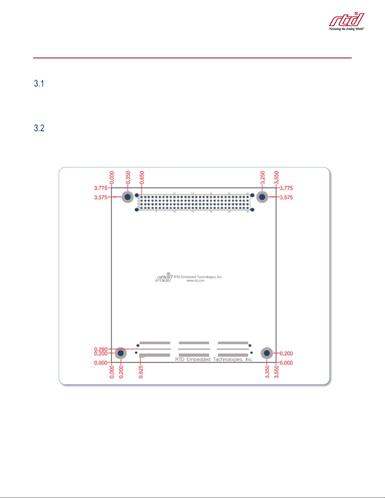
Physical Characteristics............................................................................................................................................................ 10
Connectors and Jumpers.......................................................................................................................................................... 11
3.3.1 External I/O Connectors and Jumpers 11
3.3.2 RJ45 Twisted Pair Ethernet, CN5, CN7, CN9, CN11 11
3.3.3 Twisted Pair Ethernet CN4, CN6, CN8, and CN10 12
3.3.4 Status LEDs 12
3.3.5 External Status LED Connectors CN14 and CN15 12
3.3.6 Bus Connectors 13
CN1(Top) & CN2(Bottom): PCIe Connector 13
CN3: PCI Connector 13
Steps for Installing .................................................................................................................................................................... 14
4Functional Description 15
Block Diagrams......................................................................................................................................................................... 15
BroadCom Gig-Ethernet Switch................................................................................................................................................ 15
Jumbo Frame Support .............................................................................................................................................................. 15
Intel WG82574IT Gigabit Ethernet Controller........................................................................................................................... 15
Onboard LEDs and External LED Connectors ......................................................................................................................... 16
5IDAN Connections 17
Module Handling Precautions................................................................................................................................................... 17
Physical Characteristics............................................................................................................................................................ 17
IDAN Versions .......................................................................................................................................................................... 18
5.3.1 IDAN-LAN25255HR and IDAN-LAN35255HR 18
Steps for Installing .................................................................................................................................................................... 19
6Troubleshooting 21
7Additional Information 22
PC/104 Specifications............................................................................................................................................................... 22
PCI and PCI Express Specification .......................................................................................................................................... 22
8Limited Warranty 23