RTD Embedded Technologies, Inc. | www.rtd.com iv LAN35H08HR-D & LAN35E08HR-D User’s Manual
Table of Contents
1Introduction 6
Product Overview........................................................................................................................................................................ 6
Board Features ........................................................................................................................................................................... 6
Ordering Information................................................................................................................................................................... 7
Contact Information .................................................................................................................................................................... 8
1.4.1 Sales Support 8
1.4.2 Technical Support 8
2Specifications 9
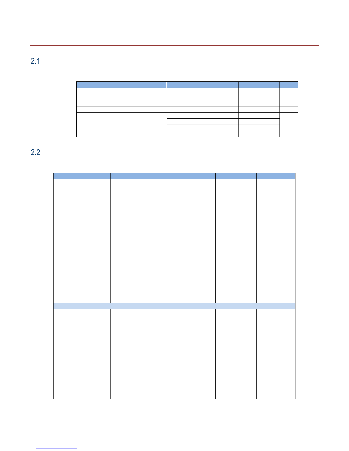
Operating Conditions .................................................................................................................................................................. 9
Electrical Characteristics ............................................................................................................................................................ 9
3Board Connection 10
Board Handling Precautions ..................................................................................................................................................... 10
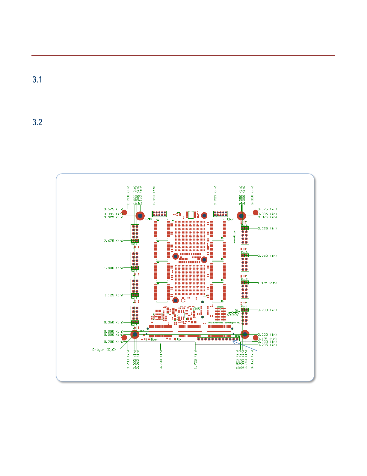
Physical Characteristics............................................................................................................................................................ 10
Connectors................................................................................................................................................................................ 12
3.3.1 External I/O Connectors 13
3.3.2 10-pin DIL Twisted Pair Ethernet, Port 1 –Port 8 (LANx08HR-D only) 13
3.3.3 RJ45 Twisted Pair Ethernet, Port 1 –Port 8 (LANx08HR-RJ only) 14
3.3.1 12-pin SIL Power, CN6 (LAN35H08HR only) 14
3.3.2 Status LEDs 14
3.3.3 External Status LED Connectors CN7 and CN9 14
3.3.4 CN1 (Top) & CN2 (Bottom) Bus Connectors 15
Steps for Installing .................................................................................................................................................................... 15
4Functional Description 17
Block Diagrams......................................................................................................................................................................... 17
BroadCom Gig-Ethernet Switch................................................................................................................................................ 18
Jumbo Frame Support .............................................................................................................................................................. 18
Intel WG82574IT Gigabit Ethernet Controller........................................................................................................................... 19
Onboard LEDs and External LED Connectors ......................................................................................................................... 19
5IDAN Connections 20
Module Handling Precautions................................................................................................................................................... 20
Physical Characteristics............................................................................................................................................................ 20
IDAN Versions .......................................................................................................................................................................... 21
5.3.1 IDAN-LAN35H08HR & IDAN-LAN35E08HR 21
Steps for Installing .................................................................................................................................................................... 24
6Troubleshooting 25
7Additional Information 26
PC/104 Specifications............................................................................................................................................................... 26
PCI and PCI Express Specification .......................................................................................................................................... 26
8Limited Warranty 27