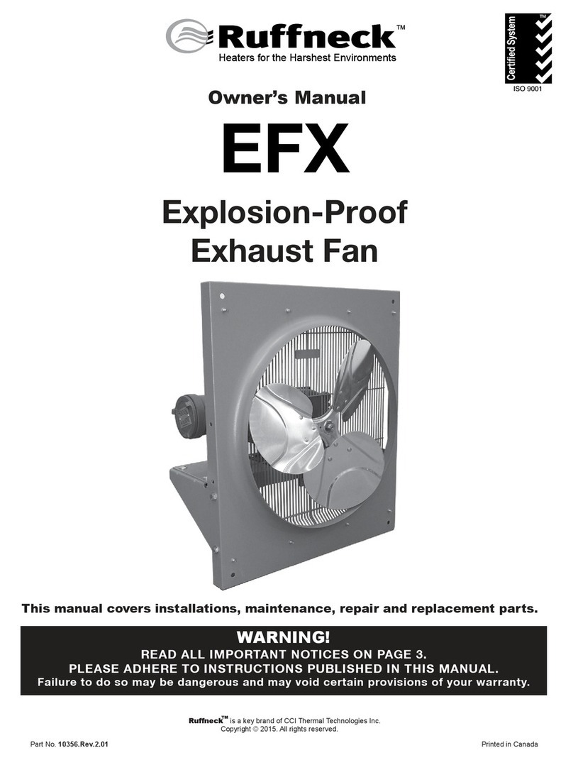
Ruffneck EFX Series Guide

Part No.10356.Rev.2.03 Feb 2018 Printed in Canada
EFX Series
Explosion-Proof Exhaust Fan
Installation, Operation, & Maintenance Instructions
ISO 9001
WARNING! Read all important information notices on page 3.
EFX - 12 - A - 1A
Model
Series
Fan Size
12 - 12"
16 - 16"
20 - 20"
24 - 24"
30 - 30"
Cabinet Material
A - Epoxy powder coated
carbon steel
B - Heresite®phenolic
coated carbon steel
C - Stainless steel
Model Coding
Motor Enclosure
1 - Totally enclosed
2 - Explosion-proof, Groups C, D, E,
F, & G
3 - Washdown
4 - Washdown stainless steel
5 - Special motor
VPhase Hz
A115 160
B208 160
C208 360
D 230 1 60
E 230 3 60
F460 160
G460 360
H575 360
I220 150
J380 350
K440 350
Motor Electrical Specications
Only available for Class I Group D, Class II Group F & G.
Consult factory for motor availability.

Ruffneck™ is a key brand Thermon Heating Systems, Inc.
Copyright © 2018. All rights reserved.
TABLE OF CONTENTS
A. Fan Maintenance Checklist 3
A.1 Periodic ................................................................................................................3
A.2 Annual.................................................................................................................. 3
B. Important Notices 4
C. Installation 4
C.1 Location ............................................................................................................... 4
C.2 Mounting.............................................................................................................. 4
C.3 Temperature Control ............................................................................................ 4
C.4 Final Inspection ....................................................................................................4
D. Parts List 6
E. General Specifications 7
F. Repair & Replacement 8
F.1 Motor, Fan, and Fan Guard.................................................................................... 8

33
Fan Maintenance Checklist
A. FAN MAINTENANCE CHECKLIST
WARNING
WARNING. Fan should only be serviced by qualied personnel with HVAC equipment
experience. Disconnect fan from power supply before servicing fan. Lock the switch in the
“OFF” (open) position and/or tag the switch to prevent unexpected power application.
A.1 Periodic
• Clean
Fan
Fan Guard
Motor
Backdraft Dampers
Stormhood
NOTE: Remove dust using compressed air. Do not spray with
water or solvents.
• Check
Motor for smooth, quiet operation.
Dampers for proper angle and tightness.
A.2 Annual
• Mechanical
Check motor shaft bear play. Replace motor if
play is excessive or motor does not run quietly
and smoothly. Motor bearings are persmanently
lubricated.
Check fan. Replace immediately if cracked or
damaged.
Check the tightness of all hardware. All nuts and
bolts, including mounting hardware, must be tight.
Turn fan on for a minimum of 15minutes.
Check for air exiting fan through dampers and
smooth running of fan motor.
• Electrical
Check all terminal connections and condutors.
Tighten loose connections. Conductors with
damaged insulation must be replaced.
For assistance, please call
Toll Free: 1-800-661-8529
U.S. & Canada
(before and as required during heating season) (before heating season)

4
4
Important Notices / Installation
B. IMPORTANT NOTICES
WARNING
WARNING. Read and adhere to the following
installation instructions. FAILURE TO DO SO MAY
RESULT IN SEVERE OR FATAL INJURY AND/OR
POSSIBLE VOIDING OF THE WARRANTY.
1. Read and follow the instructions in this manual.
2. Fans are to be installed and serviced only by qualied
personnel experienced in electrical and HVAC work.
3. Installation and wiring of the fan must adhere to all
applicable codes.
4. It is essential that any fan, that will be used in a hazardous
(classied) location, is equipped with an electric motor
approved for such service.
5. Do not operate fan in atmospheres which are corrosive to
steel or aluminum, unless it has been coated with a factory
approved protective coating.
6. Fan must be kept clean. When operating in a dirty
environment, regularly clean fan and fan guard. Follow
the recommended maintenance procedures. Refer to
SectionA. Fan Maintenance Checklist, page3 for
details.
7. Use factory approved replacement parts only.
8. If there are any questions or concerns regarding the fan,
contact the factory. Refer to the last page of this manual
for details.
9. Heater is to be used only in atmospheres having an
ignition temperature higher than the heater’s maximum
rated operating temperature as shown on the heater data
plate. Refer to applicable electrical codes for additional
information.
10. Installer to provide certied Ex “d” sealed ttings and
stopping boxes for the same gas groups as the apparatus.
C. INSTALLATION
The installation instructions provide a general guideline for the
installation and wiring of the exhaust fan. All applicable codes must
be adhered to.
C.1 Location
1. For optimum air exhaust, the fan(s) should be installed as
follows:
1.1 There are no obstructions that may impede the fans
air inlet or discharge.
1.2 The air discharge is directed away from building.
1.3 The air discharge is not directed at a thermostat.
1.4 For warehouses or large workshops it may be
acceptable to use fewer, larger fans.
2. This unit can exhaust warm or cool air depending on customer
conditions. Be aware of problems each can produce.
3. For installation within a Hazardous Location, cable
entries and conduit should be suitable for operations in
hazardous locations and rated IP 54.
C.2 Mounting
1. The Exhaust Fan is designed to be installed in an upright
and level position.
2. Fan(s) are designed to be mounted from the rear using four
3/8" holes. For fan dimensions, see Figure 1, page5.
3. The mounting structure must be strong enough to:
3.1 Support the fans weight (refer to Section E. General
Specications, page7).
3.2 Provide sufcient stiffness to prevent excessive
vibration.
3.3 Withstand abusive situations such as transportable
installations.
3.4 If Exhaust Fan is installed on a wall thinner than 4",
customer will need to install shims to bring face of
fan away from mounting surface.
4. Mounting Clearances
4.1 Leave at least 20" (500mm) clearance between the
rear of the motor and the nearest obstruction.
4.2 Clearance equal to the height of the fan shroud
above, or beneath is required for easy fan or motor
replacement.
C.3 Temperature Control
If required, the fan output may be thermostatically controlled by a
remotely mounted thermostat.
C.4 Final Inspection
1. Before application of electrical power:
1.1 Check that all connections are secured and comply
with the applicable wiring diagram and code
requirements.
1.2 Conrm the power supply is compatible with the
data plate rotating on motor.
1.3 Remove any foreign objects from fan.
1.4 Ensure all electrical covers are well secured.
1.5 Ensure the fan rotates freely counterclockwise when
viewed from the rear of the fan and air exits through
the dampers.

55
Installation
B F
G
A
E
AIR FLOW
C
D
C
D
C
D
C
D
EFX-12 EFX-16 EFX-20 EFX-24 EFX-30
mm 392.1 377.8 409.6 393.7 396.9
in 15.4 14.9 16.1 15.5 15.6
mm 461.9 588 687.9 787.9 942.3
in 18.2 23.2 27.1 31 37.1
mm 410 512.5 614.5 714.5 862.5
in 16.1 20.2 24.2 28.1 34
mm 79.4 57.2 91.7 76.2 88.9
in 3.1 2.2 3.6 3 3.5
mm 373.3 475.6 577.3 677.3 835.3*
in 14.7 18.7 22.7 24.7 32.9
mm 411.1 537.2 637.1 737.1 891.5
in 16.2 21.2 25.1 29 35.1
mm 359.2 461.7 563.7 663.7 811.7
in 14.1 18.2 22.2 26.1 32
* This dimension is the minimum square opening size
E
F
G
DIMENSION
A
B
C
D
BF
G
A
E
AIR FLOW
C
D
C
D
C
D
C
D
EFX-12 EFX-16 EFX-20 EFX-24 EFX-30
mm 392.1 377.8 409.6 393.7 396.9
in 15.4 14.9 16.1 15.5 15.6
mm 461.9 588 687.9 787.9 942.3
in 18.2 23.2 27.1 31 37.1
mm 410 512.5 614.5 714.5 862.5
in 16.1 20.2 24.2 28.1 34
mm 79.4 57.2 91.7 76.2 88.9
in 3.1 2.2 3.6 3 3.5
mm 373.3 475.6 577.3 677.3 835.3*
in 14.7 18.7 22.7 24.7 32.9
mm 411.1 537.2 637.1 737.1 891.5
in 16.2 21.2 25.1 29 35.1
mm 359.2 461.7 563.7 663.7 811.7
in 14.1 18.2 22.2 26.1 32
* This dimension is the minimum square opening size
E
F
G
DIMENSION
A
B
C
D
Figure 1 – Dimensions
Table1 – Dimensions
Dim. EFX-12 EFX-16 EFX-20 EFX-24 EFX-30
Amm 392.1 377.8 409.6 393.7 396.9
in 15.4 14.9 16.1 15.5 15.6
Bmm 461.9 588 687.9 787.9 942.3
in 18.2 23.2 27.1 31.0 37.1
Cmm 410.0 512.5 614.5 714.5 862.5
in 16.1 20.2 24.2 28.1 34.0
Dmm 79.4 57.2 91.7 76.2 88.9
in 3.1 2.2 3.6 3.0 3.5
E* mm 373.3 475.6 577.3 677.3 835.3
in 14.7 18.7 22.7 24.7 32.9
Fmm 411.1 5 37. 2 6 37.1 737.1 891.5
in 16.2 21.12 25.1 29.0 35.1
Gmm 359.2 461.7 563.7 663.7 811.7
in 14.1 18.2 22.2 26.1 32.0
*This dimension is the minimum square opening size.

6
6
Parts List
D. PARTS LIST
15
13
9
7
17
1
6
2
10
11
12
14
14
5
12
16
8
3
4
4
Table2 – EFX Parts List
Item EFX-12 EFX-16 EFX-20 EFX-24 EFX-30 Description Qty
110192 10193 10194 10195 10196 Panel, shroud 1
2*Provide motor voltage, phase, horsepower and service classication when ordering replacment motor. Motor 1
35456 5457 5458 5459 5460 Fan guard 2
49671 Grill connector 2
53785 3786 3787 5433 9639 Channel, motor mount 1
61176 Label Ruffneck™ 1
73789 9638 Bracket, motor mount, right 1
83788 9637 Bracket motor mount, left 1
910204 Label EFX 1
10 3258 Washer #10 SAE Flat 8
11 3257 Screw, 10-24, 5/8" lg, cutting 8
12 1521 Bolt, 5/16 NC, 3/4" lg. 8
13 1518 Washer, 5/16 SAE 4
14 3382 Nut, 5/16 NC hex ange locking 12
15 1517 Bolt, 5/16-18 UNC x 3/4" lg. 4
16 1456 Rivet 1/8 2
17 11284 1378 1382 1389 1386 Fan 1

77
General Specications
E. GENERAL SPECIFICATIONS
1. Hazardous Location
Classication
Class I, Div 1 & 2, Groups C, D
Class II, Div 1 & 2, Groups E, F, G.
Temperature Code: T3B 165°C (329°F)
EAC, Ex d IIB T3 Gb X
2. Ambient Temperature -20°C (4°F) to 40°C (104°F)
3. Approvals Motors are CSA approved and/or UL listed.
4. Fan Aluminum blade. Steel spider and hub with 5/8" (15.875mm) bore. Optional Heresite®
coating for corrosive atmospheres.
5. Fan Guard Split design with close wire spacing, meets OSHA requirements.
6. Motors CSA approved and/or UL listed permanently lubricated ball bearing type with rigid
base. Explosion-proof or totally enclosed construction. All standard voltages for 60
and 50 hertz are available.
7. Frame Material 16ga. (0.060" or 1.52mm) epoxy-coated steel. Optional stainless steel or Heresite®
coating for corrosive atmospheres.
8. Mounting Four 3/8" (9.5mm) diameter holes. Must be mounted to a rigid structure.
Table3 – Specications
EFX-12 EFX-16 EFX-20 EFX-24 EFX-30
Fan Diameter in 12 16 20 24 30
mm 305 406 508 610 762
Motor* 1/2 HP, 60 Hz
1/2 HP, 0.373 kW
Air Flow Rating
@70°F (21°C)
CFM 850 1825 3760 4180 4759
m/³hr 1444 3101 6388 7102 8086
Motor Speed RPM 1725 1140
Net Weight lbs 48.0 52.0 56.0 61.0 67.0
kg 21.8 23.6 25.4 27.7 30.4
Shipping Weight lbs 56.0 62.0 68.0 81.0 87.0
kg 25.4 28.1 30.8 36.7 39.5
Dimensions
Width in 16.1 20.2 24.2 28.1 34.0
mm 410 513 615 715 863
Height in 18.2 23.1 27.1 31.0 37.1
mm 462 588 688 788 942
Depth in 15.4 14.9 16.1 15.5 15.6
mm 392 378 410 394 397
*50Hz units also available.

8
8
Repair & Replacement
F. REPAIR & REPLACEMENT
WARNING
WARNING. Fan should only be serviced by qualied
personnel with HVAC equipment experience. Disconnect
fan from power supply before servicing fan. Lock the
switch in the “OFF” (open) position and/or tag the switch
to prevent unexpected power applications.
1. After repairing any component:
1.1 Check that electrical connections are correct and
secure.
1.2 Remove any foreign material from enclosures.
1.3 Install and secure all covers.
1.4 Ensure that all fasteners are tight.
1.5 Remove all foreign objects from fan.
1.6 Ensure air exits through dampers and fan rotates
counterclockwise when viewed from rear of fan (see
Figure 2, page8).
F.1 Motor, Fan, and Fan Guard
1. Remove the (8) screws and washers that are holding the
fan grills to the shroud (see Figure 3, page8).
2. Remove the (4) bolts and nuts that are holding the motor
to the motor mount (see Figure 4, page9).
3. Remove the motor, fan and grills from the frame by lifting
the motor (see Figure 5, page9).
4. Before removing the fan, measure and record the
location of the fan hub on the motor shaft (see Figure 6,
page9). If fan is difcult to remove, use a gear puller
on the fan hub.
5. To reassemble, place grills with grill clips onto motor (see
Figure 6, page9) then position fan on motor shaft and
tighten set screws.
6. Place motor assembly onto motor mount and fasten the
fan guard to cabinet.
7. Center fan in shroud opening. Leave approximately 1/16"
to 3/16" (1.6mm to 4.8mm) gap between the motor and
fan guard. (see Figure 7, page9).
8. Bolt motor to motor mount. Manually spin the fan blade to
ensure it rotates freely before applying power.
9. Air must exit through dampers and fan must rotate counter
clockwise when viewing from the rear of the fan (see
Figure 3, page8).
Fan rotation
Mounting Holes
(on top and bottom)
Air Intake
Support back of motor
Figure 2
Grill Screws (4 on top)
Grill Screws (4 on bottom)
Figure 3

99
Repair & Replacement
Motor bolts
(2 on each side)
Figure 4
Figure 5
Fan locking bolt
Figure 6
1/16" to 3/16"
(1.6mm to 4.8mm)
Figure 7

NOTES
NOTES

NOTES
NOTES

PLEASE ADHERE TO INSTRUCTIONS IN THIS MANUAL
Failure to do so may be dangerous and may void certain provisions of
your warranty.
For further assistance, please call 24hr hotline: 1-800-661-8529 (U.S.A. and Canada)
Please have model and serial numbers available before calling.
Oakville
1-800-410-3131
1-905-829-4422
F 905-829-4430
Orillia
1-877-325-3473
1-705-325-3473
F 705-325-2106
WARRANTY:Under normal use the Company warrants to
the purchaser that defects in material or workmanship will be
repaired or replaced without charge for a period of 18 months
from date of shipment, or 12 months from the start date of
operation, whichever expires rst. Any claim for warranty must
be reported to the sales ofce where the product was purchased
for authorized repair or replacement within the terms of this
warranty.
Subject to State or Provincial law to the contrary, the Company
will not be responsible for any expense for installation, removal
from service, transportation, or damages of any type whatsoever,
including damages arising from lack of use, business interruptions,
or incidental or consequential damages.
The Company cannot anticipate or control the conditions of
product usage and therefore accepts no responsibility for
the safe application and suitability of its products when used
alone or in combination with other products. Tests for the
safe application and suitability of the products are the sole
responsibility of the user.
This warranty will be void if, in the judgment of the Company,
the damage, failure or defect is the result of:
• Vibration, radiation, erosion, corrosion, process
contamination, abnormal process conditions, temperature
and pressures, unusual surges or pulsation, fouling,
ordinary wear and tear, lack of maintenance, incorrectly
applied utilities such as voltage, air, gas, water, and others
or any combination of the aforementioned causes not
specically allowed for in the design conditions or,
• Any act or omission by the Purchaser, its agents, servants
or independent contractors which for greater certainty, but
not so as to limit the generality of the foregoing, includes
physical, chemical or mechanical abuse, accident,
improper installation of the product, improper storage
and handling of the product, improper application or the
misalignment of parts.
No warranty applies to paint nishes except for manufacturing defects
apparent within 30 days from the date of installation.
The Company neither assumes nor authorizes any person to assume for it
any other obligation or liability in connection with the product(s).
The Purchaser agrees that all warranty work required after the initial
commissioning of the product will be provided only if the Company
has been paid by the Purchaser in full accordance with the terms and
conditions of the contract.
The Purchaser agrees that the Company makes no warranty or
guarantee, express, implied or statutory, (including any warranty of
merchantability or warranty of tness for a particular purpose) written
or oral, of the Article or incidental labour, except as is expressed or
contained in the agreement herein.
LIABILITY: Technical data contained in the catalog or on the
website is subject to change without notice. The Company reserves
the right to make dimensional and other design changes as required.
The Purchaser acknowledges the Company shall not be obligated
to modify those articles manufactured before the formulation of the
changes in design or improvements of the products by the Company.
The Company shall not be liable to compensate or indemnify the
Purchaser, end user or any other party against any actions, claims,
liabilities, injury, loss, loss of use, loss of business, damages, indirect
or consequential damages, demands, penalties, nes, expenses
(including legal expenses), costs, obligations and causes of action of
any kind arising wholly or partly from negligence or omission of the
user or the misuse, incorrect application, unsafe application, incorrect
storage and handling, incorrect installation, lack of maintenance,
improper maintenance or improper operation of products furnished
by the Company.
Edmonton
1-780-466-3178
F 780-468-5904
5918 Roper Road
Alberta, Canada T6B 3E1
Houston
1-855-219-2101
1-281-506-2310
F 281-506-2316
Denver
1-855-244-3128
1-303-979-7339
F 303-979-7350

Part No.10356.Rev.2.03 fev 2018 Imprimé au Canada
Série EFX
Ventilateur d’évacuation antidéagrant
Ce guide traite de l’installation, de la maintenance,
de la réparation et des pièces.
ISO 9001
AVERTISSEMENT! Lisez tous les avis d’information importants de page 3..
EFX - 12 - A - 1A
Série du
Modèle
Taille du
ventilateur
12 - 12"
16 - 16"
20 - 20"
24 - 24"
30 - 30"
Matériau du cabinet
A - Acier au carbone enduit
d’époxyde
B - Acier au carbone enduit
phénolique HeresiteMD
C - Acier inoxydable
Code du modéle
Boîtier du moteur
1 - Construction totalement fermée
2 - Antidéagrante, groupes C, D, E,
F, & G
3 - Washdown
4 - Washdown en acier inoxydable
5 - Moteur spécial
VPhase Hz
A115 160
B208 160
C208 360
D 230 1 60
E 230 3 60
F460 160
G460 360
H575 360
I220 150
J380 350
K440 350
Caractéristiques électriques
du moteur
Seulement offert pour la classe 1 groupe D, classe 2 groupes F et G.
S’adresser à l’usine pour la disponibilité des moteurs.
Chauffages pour les environnements les plus rigoureux
MC

TABLE DE MATIÈRES
A. Liste de vérification pour l’entretien du ventilateur 15
A.1 Periodic .............................................................................................................. 15
A.2 Annuel................................................................................................................ 15
B. Avis Importants 16
C. Installation 16
C.1 Emplacement ..................................................................................................... 16
C.2 Montage............................................................................................................. 16
C.3 Réglage de la température................................................................................. 16
C.4 Inspection finale ................................................................................................. 17
D. Liste des pièces 18
E. Spécifications générales 20
F. Réparation et remplacement 21
F.1 Moteur, ventilateur, et grille de protection ............................................................ 21

1515
Liste de vérication pour l’entretien du ventilateur
A. LISTE DE VÉRIFICATION POUR L’ENTRETIEN DU VENTILATEUR
A.1 Periodic
• Nettoyage
Ventilateur
Grille de protection
Moteur
Registres empêchant les refoulements d’air
Stormhood
Remarque: Enlever la poussière à l’aide d’air comprimé. Ne pas vaporiser d’eau
ou de solvants. Ne pas immerger dans l’eau ou des solvants.
• Vérication
Fonctionnement régulier et silencieux du moteur.
Les registres permettent un angle et un serrage
adéquats.
A.2 Annuel
• Mécanique
Jeu et palier de l’arbre de moteur. Remplacer
le moteur si le jeu est excessif ou si le moteur ne
fonctionne pas silencieusement et régulièrement.
Les paliers du moteur sont lubriés de manière
permanente.
Ventilateur. Le remplacer immédiatement s’il est
craqué ou endommagé.
Tout le matériel doit être bien serré. Tous les
écrous et boulons, y compris ceux du matériel de
montage, doivent être bien serrés.
Faire fonctionner le ventilateur pendant au moins
15minutes. S’assurer que l’air est évacué du
ventilateur au moyen des registres et que le
moteur du ventilateur fonctionne correctement.
• Électrique
Tous les connecteurs et conducteurs. Serrer
ceux qui sont lâches. Les conducteurs dont
l’isolation est endommagée doivent être
remplacés.
AVERTISSEMENT
AVERTISSEMENT. Seul le personnel qualié détenant de l’expérience
avec l’équipement CVCA doit effectuer l’entretien des ventilateurs.
Débrancher le ventilateur du bloc d’alimentation avant d’en effectuer
l’entretien. Verrouiller l’interrupteur en position « OFF » (ouvert) ou mettez
une étiquette sur l’interrupteur pour éviter d’alimenter l’appareil en
puissance de manière inattendue.
(avant et au besoin durant la saison de chauffage)
(avant la saison de chauffage)

16
16
Avis Importants
B. AVIS IMPORTANTS
AVERTISSEMENT
AVERTISSEMENT. Lire et respecter ce qui suit.
L’omission de se faire peut entraîner des blessures
graves, voire la mort. LA GARANTIE SERA
ANNULÉE.
1. Lire et suivre toutes les instructions du présent manuel.
2. Seul le personnel qualié détenant de l’expérience
de travail avec l’équipement CVCA doit installer les
ventilateurs et en effectuer l’entretien.
3. L’installation et le câblage du ventilateur doivent être
conformes à tous les codes applicables.
4. Il est essentiel que tout ventilateur destiné à une utilisation
dans un emplacement dangereux (classié) soit doté d’un
moteur électrique approuvé pour cet usage.
5. Ne pas faire fonctionner le ventilateur dans des
atmosphères corrosives à l’acier ou à l’aluminium, à moins
qu’il soit protégé par un enduit approuvé en usine.
6. Le ventilateur doit être gardé propre. Lorsqu’il est utilisé
dans un environnement sale, le ventilateur et sa grille de
protection doivent être nettoyés régulièrement. Suivre
les directives d’entretien recommandées. Se reporter
à la section A. Liste de vérication pour l’entretien du
ventilateur, page15 pour obtenir davantage de détails.
7. Utiliser seulement des pièces de remplacement
approuvées par le fabricant.
8. Pour toute question ou préoccupation concernant ce
ventilateur, contacter le fabricant. Consulter la dernière
page du présent manuel pour de plus amples détails.
9. L’appareil de chauffage doit être utilisé uniquement dans
des atmosphères ayant une température d’allumage
supérieure à la température de fonctionnement maximale
indiquée sur la plaque signalétique de l’appareil. Se
reporter aux codes électriques applicables pour obtenir de
l’information supplémentaire.
10. L’installateur doit fournir des raccords d’étanchéité et
des manchons coupe-feu homologués « Ex d » qui
correspondent aux groupes de gaz du dispositif.
C. INSTALLATION
Les directives d’installation donnent une idée générale de
l’installation et du câblage de l’aérotherme. Tous les codes
applicables doivent être respectés.
C.1 Emplacement
1. Pour une évacuation d’air optimale, le ventilateur devrait
être installé comme suit :
1.1 Il n’y a aucune obstruction qui peut entraver l’entrée
ou l’évacuation d’air du ventilateur.
1.2 La sortie d’air est dirigée vers l’extérieur de
l’immeuble.
1.3 La sortie d’air n’est pas dirigée du thermostat.
1.4 Dans le cas d’entrepôts ou de grands ateliers, il
peut être judicieux d’opter pour des ventilateurs de
grande taille, moins nombreux.
2. Cette unité peut expulser de l’air froid ou chaud, en
fonction des conditions du client. Ayez conscience des
problèmes.
3. Dans le cas de l’installation dans un endroit dangereux, les
entrées de câble et les conduits doivent être aptes à être
utilisés dans les endroits dangereux et cotés IP 54.
C.2 Montage
1. Le ventilateur d’évacuation est conçu de manière à être
installé dans une position verticale et de niveau.
2. Les ventilateurs sont conçus pour être montés à partir
de l’arrière au moyen de quatre trous de 3/8po. Pour les
dimensions du ventilateur. Voir la Figure 1, page17.
3. La structure de montage doit être sufsamment solide
pour :
3.1 Supporter le poids du ventilateur (se référer à la
section E. Spécications générales, page20)
3.2 Offrir une rigidité sufsante pour prévenir les
vibrations excessives.
3.3 Résister aux situations difciles comme les
installations transportables.
3.4 Si le ventilateur d’évacuation est installé sur
un mur d’une épaisseur de moins de 4po, les
clients devront installer des cales an d’éloigner le
ventilateur de la surface de montage.
4. Espacements de montage
4.1 Il est conseillé de prévoir une distance de
dégagement d’au moins 500mm (20po) entre
l’arrière du moteur et l’objet le plus près.
4.2 Un espacement égal à la hauteur du capot de
ventilateur, au-dessus ou au-dessous, est exigé pour
le remplacement facile du ventilateur ou du moteur.
C.3 Réglage de la température
La puissance du ventilateur peut être contrôlée par thermostat par
un thermostat monté à distance, au besoin.

1717
Installation
C.4 Inspection nale
1. Avant l’application de l’alimentation électrique :
1.1 Vérier que tous les raccordements sont sécurisés
et conformes au diagramme de câblage et aux
exigences du ou des codes applicables.
1.2 Conrmer que la source d’alimentation est
compatible avec la cote de l’appareil, indiquée sur sa
plaque signalétique.
1.3 Retirer tout corps étranger du ventilateur.
1.4 S’assurer que tous les couvercles électriques sont
bien sécurisés.
1.5 S’assurer que le ventilateur tourne librement dans le
sens antihoraire lorsqu’observé à partir de l’arrière
du ventilateur et que l’air est évacué par les registres.
Tableau 1 – Dimensions
Dim. EFX-12 EFX-16 EFX-20 EFX-24 EFX-30
Amm 392.1 377.8 409.6 393.7 396.9
po 15.4 14.9 16.1 15.5 15.6
Bmm 461.9 588 687.9 787.9 942.3
po 18.2 23.2 27.1 31.0 37.1
Cmm 410.0 512.5 614.5 714.5 862.5
po 16.1 20.2 24.2 28.1 34.0
Dmm 79.4 57.2 91.7 76.2 88.9
po 3.1 2.2 3.6 3.0 3.5
E* mm 373.3 475.6 577.3 677.3 835.3
po 14.7 18.7 22.7 24.7 32.9
Fmm 411.1 5 37. 2 637.1 737.1 891.5
po 16.2 21.12 25.1 29.0 35.1
Gmm 359.2 461.7 563.7 663.7 811.7
po 14.1 18.2 22.2 26.1 32.0
B F
G
A
E
AIR FLOW
C
D
C
D
C
D
C
D
EFX-12 EFX-16 EFX-20 EFX-24 EFX-30
mm 392.1 377.8 409.6 393.7 396.9
in 15.4 14.9 16.1 15.5 15.6
mm 461.9 588 687.9 787.9 942.3
in 18.2 23.2 27.1 31 37.1
mm 410 512.5 614.5 714.5 862.5
in 16.1 20.2 24.2 28.1 34
mm 79.4 57.2 91.7 76.2 88.9
in 3.1 2.2 3.6 3 3.5
mm 373.3 475.6 577.3 677.3 835.3*
in 14.7 18.7 22.7 24.7 32.9
mm 411.1 537.2 637.1 737.1 891.5
in 16.2 21.2 25.1 29 35.1
mm 359.2 461.7 563.7 663.7 811.7
in 14.1 18.2 22.2 26.1 32
* This dimension is the minimum square opening size
E
F
G
DIMENSION
A
B
C
D
BF
G
A
E
AIR FLOW
C
D
C
D
C
D
C
D
EFX-12 EFX-16 EFX-20 EFX-24 EFX-30
mm 392.1 377.8 409.6 393.7 396.9
in 15.4 14.9 16.1 15.5 15.6
mm 461.9 588 687.9 787.9 942.3
in 18.2 23.2 27.1 31 37.1
mm 410 512.5 614.5 714.5 862.5
in 16.1 20.2 24.2 28.1 34
mm 79.4 57.2 91.7 76.2 88.9
in 3.1 2.2 3.6 3 3.5
mm 373.3 475.6 577.3 677.3 835.3*
in 14.7 18.7 22.7 24.7 32.9
mm 411.1 537.2 637.1 737.1 891.5
in 16.2 21.2 25.1 29 35.1
mm 359.2 461.7 563.7 663.7 811.7
in 14.1 18.2 22.2 26.1 32
* This dimension is the minimum square opening size
E
F
G
DIMENSION
A
B
C
D
Figure 1 – Dimensions

18
18
Liste des pièces
D. LISTE DES PIÈCES
Voir Tableau 2, page19.
15
13
9
7
17
1
6
2
10
11
12
14
14
5
12
16
8
3
4
4

1919
Liste des pièces
Tableau 2 – Liste des pièces EFX
Article EFX-12 EFX-16 EFX-20 EFX-24 EFX-30 Déscription Qty
110192 10193 10194 10195 10196 Panneau, capot 1
2*Fournir la tension du moteur, la phase, la puissance et la classication de service au moment de
commander un moteur de remplacement. Moteur 1
35456 5457 5458 5459 5460 Grille de protection 2
49671 Connecteur de grille 2
53785 3786 3787 5433 9639 Rainure, support du moteur 1
61176 Étiquette RuffneckMD 1
73789 9638 Plaque de xation, support du
moteur, côté droit
1
83788 9637 Plaque de xation, support du
moteur, côté gauche
1
910204 Étiquette EFX 1
10 3258 Rondelle plate nº 10 SAE 8
11 3257 Vis 10-24, 5/8po larg.,
découpage
8
12 1521 Boulon, 5/16 NC, 3/4po larg. 8
13 1518 Rondelle, 5/16 SAE 4
14 3382 Écrou, 5/16 NC, verr. bride
hexagonale
12
15 1517 Boulon, 5/16 NC, 3/4po larg. 4
16 1456 Rivet 1/8 2
17 11284 1378 1382 1389 1386 Ventilateur 1

20
20
Spécications générales
E. SPÉCIFICATIONS GÉNÉRALES
1. Classications
d’endroits dangereux
Classe I, Div 1 & 2, Groupes C, D
Classe II, Div 1 & 2, Groupes E, F, G
Code de température: T3B 165°C (329°F)
EAC, Ex d IIB T3 Gb X
2. Température
ambiante
-20°C (4°F) to 40°C (104°F)
3. Approbations Moteurs approuvés CSA ou homologués UL.
4. Ventilateur Pales en aluminium. Boîte de distribution et emboîtement en acier avec alésage de
15,875mm (5/8po). Revêtement HeresiteMD optionnel pour les atmosphères corrosives.
5. Grille de protection Conception fendue avec espacement des câbles minime, répond aux normes OSHA.
6. Moteurs Homologué UL/approuvé CSA, à roulement à billes totalement fermé, lubrié en
permanence et à base rigide. Construction totalement fermée ou antidéagrante. Toutes
les tensions standard pour 50 et 60 Hz sont offertes
7. Matériaux du cadre Acier d’une épaisseur 16 (0,060po ou 1,52mm) enduit d’époxyde. Revêtement en acier
inoxydable ou HeresiteMD optionnel pour les atmosphères corrosives.
8. Montage Quatre trous d’un diamètre de 9,5mm (3/8po). Doit être monté sur une structure rigide.
Tableau 3 – Spécications
EFX-12 EFX-16 EFX-20 EFX-24 EFX-30
Diamètre du
ventilateur
po 12 16 20 24 30
mm 305 406 508 610 762
Moteur* 1/2 HP, 60 Hz
1/2 HP, 0.373 kW
Débit de
circulation d’air
@70°F (21°C)
pi³/min 850 1825 3760 4180 4759
m³/hr 1444 3101 6388 7102 8086
Vitesse du
moteur Tr/min 1725 1140
Poids net lbs 48.0 52.0 56.0 61.0 67.0
kg 21.8 23.6 25.4 27.7 30.4
Poids à
l’expédition
lbs 56.0 62.0 68.0 81.0 87.0
kg 25.4 28.1 30.8 36.7 39.5
Dimensions
Width po 16.1 20.2 24.2 28.1 34.0
mm 410 513 615 715 863
Height po 18.2 23.1 27.1 31.0 37.1
mm 462 588 688 788 942
Depth po 15.4 14.9 16.1 15.5 15.6
mm 392 378 410 394 397
* *Unités de 50 Hz aussi offertes.
This manual suits for next models
5
Table of contents
Languages:
Other Ruffneck Fan manuals
Popular Fan manuals by other brands

Helios
Helios ultra Silence MiniVent M1/150 Installation and operating instructions

Blaupunkt
Blaupunkt BP2006 user manual

EDM Product
EDM Product 33918 instruction manual

Orbegozo
Orbegozo TWM 0960 instruction manual

Star Progetti
Star Progetti FRE38000 instruction manual

TZS First AUSTRIA
TZS First AUSTRIA FA-5560-4 instruction manual