1/32
Page 1-16 for DPS3012/DPS5015/DPS5020 series
Page 17-32 for DPH5005/DPH3205 series
DPS Series Constant Voltage /Constant Current
Digital Power Supply Introductions
Model: DPS3012/DPS5015/DPS5020 version: 2019-3-15
Dear users, thank you for purchasing the constant Voltage/constant Current digital power
supply produced by HANGZHOU RUIDENG TECHNOLOGIES CO., LTD, in order to let you know
more about the full function of this product, get a better experience and avoid misuse.
Please spend some time on reading this introduction. Keep it for checking again. (Please pay
attention to these red sentences)
1. Production Introduction
1.1 Production Synopsis
DPS3012/DPS5015/DPS5020 combines analog adjustment and digital control, at the
same time it is compact and powerful, and becomes the first choice for many enthusiasts and
laboratory workers. The unit offers non-volatile power off parameter storage and 10
programmable preset memory Data Groups with a shortcut recall function for groups 1 and 2.
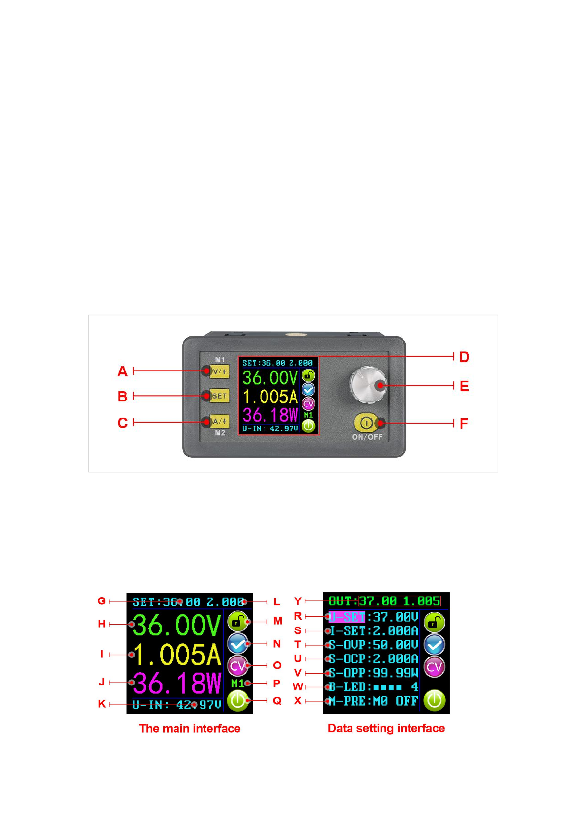
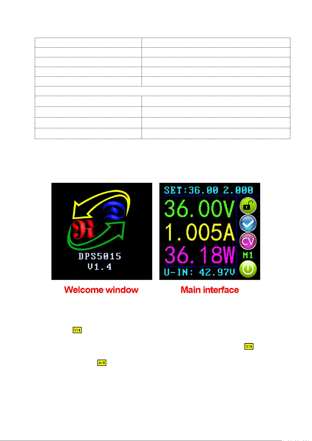
All these productions are designed with LCD display, so we can check set Voltage, set Current,
output Voltage, output current, output power, input Voltage and so on. On the right side of
the main interface, we can see output enabled or disabled, Constant Current or Constant
Voltage mode of operation, abnormal condition warning, keypad locked or unlocked state
and the Data Group in use. The data setting interface allows adjustment of Over-Current,
Over-Voltage and Over-Power protection values, Preset value, LCD brightness and whether
the power is turned on or the like.
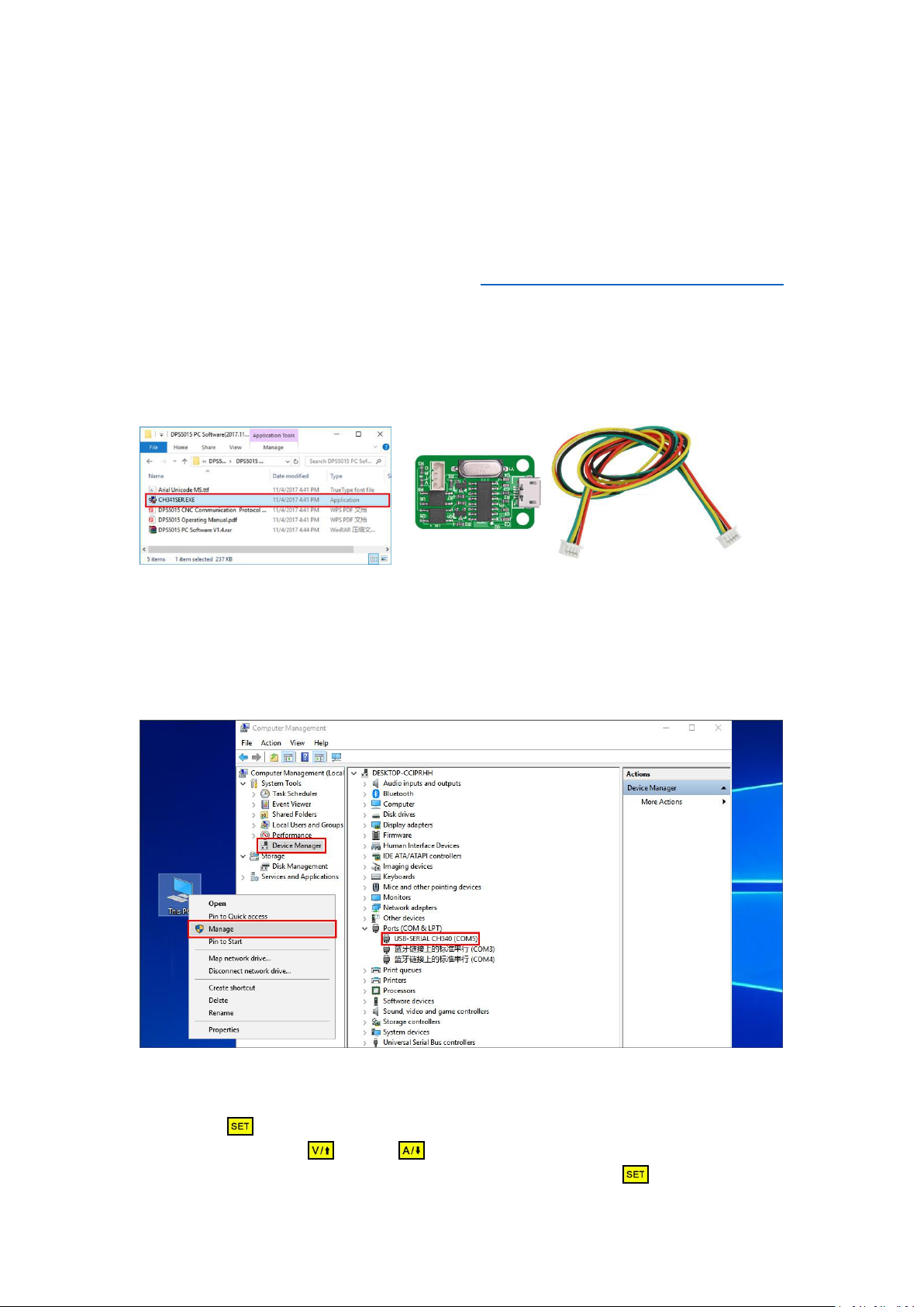
This product has 3 versions, Non-communication version, USB communication version,
USB + Bluetooth communication version. Communication version can be connected to PC,
Bluetooth version can be connected to Android mobile phone. (Note: DPS3012 only has no
communication)
This module has many advantages, small size, advanced function, good visual effect,
high operability, high-precision, it can be used independently or be inset into the device and
been widely applied.
1.2 Series Product Parameters