Ruris 425 User manual

PORTABLE BRUSH CUTTER RURIS
425/435

1
PORTABLE BRUSH CUTTER RURIS
425/435
Table of Contents
Introduction
2
Essential Checks before Commissioning and During Operation
3
Labor Protection
5
Composition of the Ruris Portable Brush Cutter
6
Technical Characteristics
7
Installation of the Brush Cutter425/435
8
Commissioning
13
Necessary Checks In Case the Ruris Portable Brush Cutter Is
Unresponsive
16
Operation of the Brush Cutter
16
Types of Knives
20
Maintenance After Running In
20
Maintenance Table
21
Movement
22
Packing
22
Storing
22
Warnings
23
Declarations of Conformity
24

2
Introduction
Thank you for choosing the RURIS product andwelcome to our
client group.
We are confident that you will be satisfied with our product for its
performance and easy operating mode.
Our experience in the field and the use of high quality materials led to
the manufacture of efficient products that will meet your demands
for many years if you follow the recommendations for use and
maintenance.
This user manual will disclose all the necessary information
about the operating mode of this product, its construction,
technical characteristics and maintenance mode.
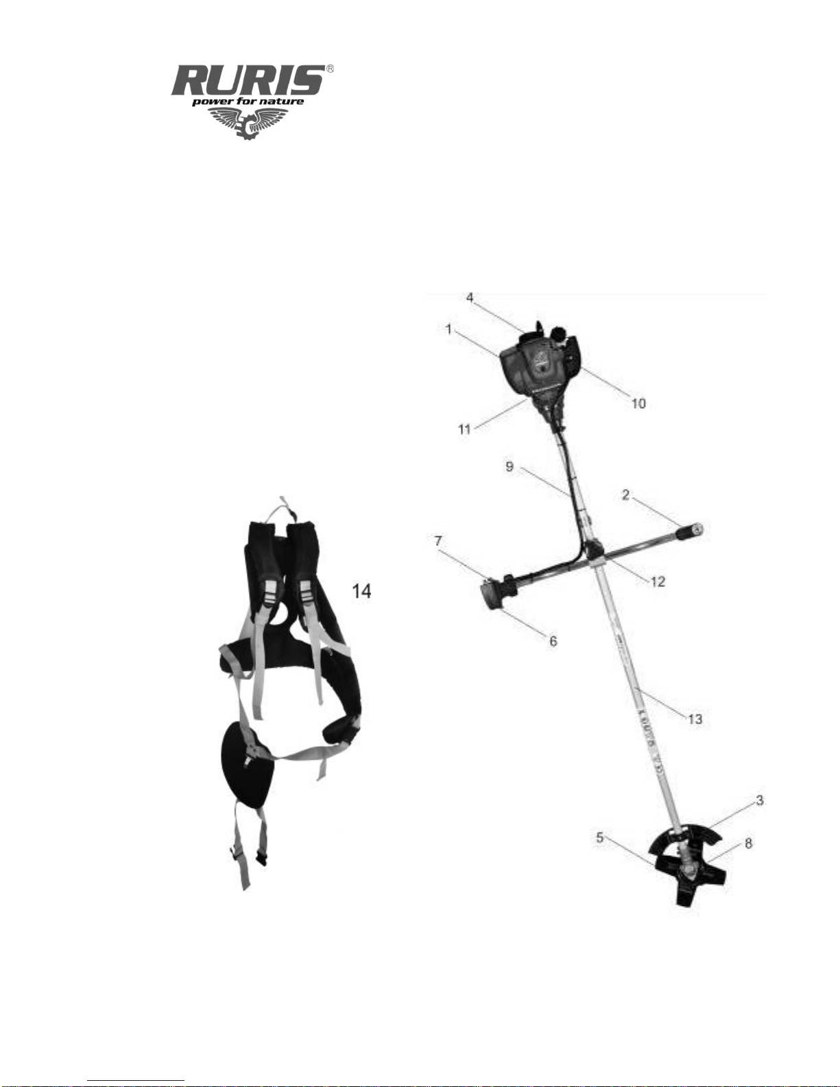
The Ruris portable brush cutters are manufactured in Romania and
specifically produced for the operation mode, and all kinds of herbs and
shrubs that are found on the surface of Romania.
At the same time we have also developed the control system of
double adjustment handles(handles with the settings back and forth
independent of each other)depending of the operator‟s way of mowing and
the angle of inclination of the slope from different alpine areas.
The RurisPortable Brush Cutters are easy to use and with an easy
maintenance thus allowing you to enjoy an assisted operation during use.
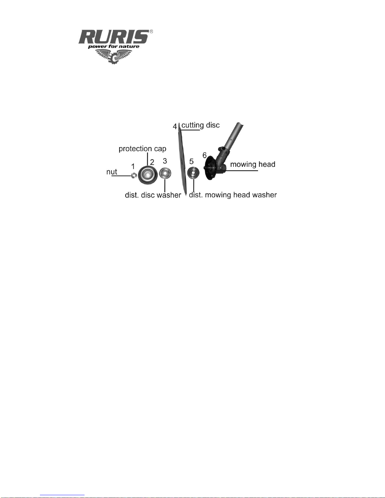
The cutting discs feature double edge disc blades to ensure an
efficient mowing in both directions, to the left or to the right.

3
1.0 Essential Checks before Commissioning and
During Operation
Make sure that:
1. The circuit of the emergency stop lever is properly assembled.
2. Oil quantity from the engine bath for the brush cutter 425: 100ml
3. Oil quantity from the engine bath for the brush cutter 435: 120ml
4. The oil used is Ruris brand: Ruris 4T/ 10W30-APISJ/CH
5. Running in must be made at idle and not under load. Three tanks
of gas at idle, no-load.
6. The reduction gear of the mowing head is filled with graphite
grease, the indicated level is given by the grease located on the
top of the screw from the supply area according to the installation
mode shown below according to figure 1.
Fig. 1
Fig. 1.1
7. The coupling, decoupling levers are working and respond to
commands by gently pulling the starter rope.
8. Mounting of the cutter disc is properly made according to the figure
below - fig. 1.2

4
Attention! When you mount the cutter disc, use the lock to unfasten the
clamp nut and the retainer clockwise. After mounting the cutting disc make
sure that the nut is properly tightened and the cutting disc is securely
attached and there is not any warping or cracking on the surface of the
cutting disc.
Fig. 1.2
9. Operating the mowing head is made by operating the throttle lever
at maximum.
10. Fill with graphite grease the mowing head, with around 20 grams.
11. Check if the protective case of the cutting disc is properly installed.
12. Fuel the brushcutter with gas.

5
1.1 Labor Protection
Warnings:
European standards CE
Danger!
Read the user manual
Use helmets
Do not use the brush cutter at a distance of less than
15 m near other people
Use protection gloves
Use protective boots or shoes
Risk of injury of the people located near the brush cutter

6
1.2 Composition of the Ruris Portable Brush Cutter
The portable brush cutter Ruris 425/435 consists of the following elements:
1. engine
2. handle
3. protection case
4. starter roll
5. cutting disc
6. throttle handle
7. switch on/off command
8. mowing head
9. electrical wiring
10. air filter cover
11. exhaust muffler
12. set point of the handles
13. handlebar chassis
14. dual balance harness
Fig. 2

7
1.3 Technical Characteristics
Warning!
The Ruris brush cutters are not delivered with gas or oil in the engine
unit. Before commissioning, check that commissioning is made
according to the manual instructions.
Product
Brush cutter 425
Brush cutter 435
Engine manufacturer
Honda
Honda
Country of origin of the engine
Japan
Japan
Engine horsepower (HP)
1
1.3
Cubic capacity (cm³)
25
35.8
Engine duty cycle (stroke)
4
4
Ignition coil
electronic
electronic
Startup
manual
manual
Fuel
Unleaded gasoline
Unleaded gasoline
Engine oil bath capacity (ml)
100
120
Fuel tank capacity (ml)
530
630
Fuel consumption (l/h)
0.54
0.71
Transmission Manufacturer
Ruris
Ruris
Harness
Dual Balance
double
double
Chassis Guide
Aluminum
Aluminum
Vibrations right handle (m/s²)
2.36
2.39
Vibrations right handle (m/s²)
2.37
2.40
Cutting diameter (mm)
200
200
Cutting midrange for a single crossing (mm)
2100
2100
Standard equipment
4 blades knife
4 blades knife
Drive shaft flexible/rigid
rigid
rigid
Noise level (dB(A))
86
96
Noise emissions (LwA, dB(A))
85
89
Weight
6,9
7,6
Product and engine warranty, months
24
24

8
1.4 Installing the Ruris 425/435 brush cutter
Before installing and commissioning, you should make sure that the
Ruris Brush Cutter is properly assembled according to the plan of
composition of point 1.2 and respect the instructions from this manual. Only
then can you proceed to the actual commissioning.
Installation
1.4.1 Throttle lever
Install the throttle lever on the right handle, according to fig.3The plastic
handle placed in the aluminum handle guide and then fasten the plastic
handle using the crossing screw.
Fig. 3
After fastening the handle, tighten the screw on the base of the
throttle support to ensure that during operation it will not come off.

9
Perform 2-3 operation maneuvers of the throttle lever and check if
the cable slides from the minimum to the maximum race of the throttle lever
fixed on the engine fig 4.
Fig. 4
Also check the on off switch
NOTE: Do not attempt at cancelling or blocking the emergency stop lever
because you risk injuring the people located near you or putting your life in
danger.
1.4.2. Handle assembly
Loosen the screw located on the chassis guide by unfastening it
until it is free from the thread, according to fig. 5
Fig. 5

10
Bring closer the two handles and place them face to face oriented
ahead according to fig 6.
Fig. 6
Gently tighten the fixing screw of the handles and orient them on a
neutral position, fig 7.
Fig. 7

11
1.4.3 Cutting disc installation
In order to install the cutting disc you will first need to unfasten the
safety nut. To do this properly you will need the following tools: the lock and
the lever key supplied with the brush cutter.
Use the lock supplied with the Ruris brush cutter and
place it in the locking hole from fig 8.
Fig. 8
Use the key supplied with the Ruris brush cutter, secure the
safety nut and rotate clockwise to unfasten according to fig 9
Fig. 9
Move outside the shaft the plain washer and the fixing cover
fig 10
Place once again the washer on the surface of the mowing
head
Place the cutting disc with the Ruris marking towards the
mowing head.
Place correctly the protection cap and assemble the nut on the
screw shaft by tightening it counter clockwise in order to
ensure the cutting disc according to fig 10.

12
Fig. 10
Check that all the assembly is correctly assembled and that
the disc is tightly fastened without axial or transversal play.
If you fail to do this, you must immediately go to the nearest
authorized Ruris Service point to remedy this problem.
1.4.4 Assembling the mowing head protection
Assemble the mowing head protection in the attachment points
indicated on the chassis guide.
Attention! Do not use the Ruris brush cutter without this protection.
To assemble the AutoCut mowing head with thread make sure that the knife
is correctly assembled with the active cutting part in the reverse cutting
direction of the AutoCut.
1.4.5 Assembling the harness
To assemble the harness you will need to place it on your
shoulders and then fix it according to figure 11.
Fig. 11
In order to place correctly the brush cutter into the harness, make
sure that it stays balanced and does not touch the ground.
At the same time, the mounting strap where the brush cutter is set
is correctly placed, according to figure 12

13
To balance the brush cutter in relation to the harness and the
user‟s height, you will need to perform the following maneuvers:
- make sure that the mounting strap is located at a hand breadth under
the user‟s hip
- Place the brush cutter in the harness‟ safety and release it
- If the brush cutter does not stay balanced and touch with the cutting
disc the ground surface or if the brush cutter tends to be inclined from
the engine, you will need to reposition the securing system placed on
the brush cutter guide towards the engine or the cutting disc until you
find the state point of the brush cutter, according to Fig. 12
In this case operation will be made with ease without supporting the
brush cutter in hands.
Fig. 12
2.0 Commissioning
Before commissioning the Ruris brush cutter you should make sure that the
following conditions are fulfilled:
Within a radius of 5 meters on both sides of the Ruris brush cutter,
there are no people or objects with which it could come into
contact;
The brush cutter is placed horizontally on the ground;
The cables are properly fixed, respond to commands by the checks
made, without starting the engine;
The handles are properly installed and fixed;
The reduction gear has graphite grease on the screw;
The engine oil has reached an adequate level, the level is indicated
at the first course of thread, outward. See figure
The engine has a minimum of 200 ml petrol in the tank;
The throttle handle is placed on the running position to maximum
and is locked in this position according to fig.11;
The on/off switch is placed on the “on” position according to fig.14
The cutting disc is properly installed and fixed, secured with the
safety nut;
All the screws of the brush cutter are tightened accordingly.

14
Fig. 13
2.1 Engine startup
Place the brush cutter horizontally on the ground
Prime the carburetor with petrol by 3 successive presses of the
petrol pump
The throttle handle and the switch are correctly placed for startup
Place the air flap in the “open” position according to fig. 13
Fully push the throttle lever (Fig. 14.1)
Push the block button (Fig. 14.2)
Fig. 14.1 Fig. 14.2
Switch the switcher on “Start” position
Fig. 14.3
Release the throttle lever
With your left hand, strongly grab the shaft tube of the brush cutter
and with your right hand, hardly pull the starting rope.

15
Secure tightly the guide of the brush cutter with your left hand and
boldly pull the starter rope with your right hand.
Pulling the rope must be made in two steps. The first step will be
made by an easy pull of the starter until the rope has come out of
the starter roll about 150-200mm and you can fill the engine
compression. The second step will be pulling powerfully and greatly
without interruption (pull the starter rope until the level of your
shoulders) according to fig.15
Pulling is carried out until the engine starts. After which you gently
switch the air flap on the „open‟ position according to figure 13, until
the engine runs properly.
In order for the engine to work at idle, operate by gripping the
throttle lever.
ATTENTION! Do not be brusque when pulling the starter because you
risk damaging the entire starter set.
Pulling is always made by prestressing the starter rope.
Fig. 15
2.2 Stopping the engine
Stopping the engine of the brush cutter is made as follows:
Release the throttle lever and let the engine to run for about 2
minutes.
Push forward the switch in the „stop‟ position(STOP)

16
3.0 Necessary checks if the Ruris brush cutter does not
answer to commands
When the engine does not start:
1. Check if the ignition is ON.
2. Check if there is enough fuel.
3. Check if there is enough petrol in the tank.
4. Check if the petrol reaches the carburetor.
5. Check if the sparkle plug gives any sparks.
6. Check if the fuel is older than 2 weeks because it risks losses
of octane.
WARNING:If the Ruris brush cutter does not respond to commands or does
not work properly you need to address immediately to an authorized Ruris
Service. 4.0 Brush cutter operation
The Ruris brush cutters are products that allow an easy choice of the mowing
mode without performing successive setting and maintenance maneuvers.
The Ruris brush cutters create a unit body with the user and provide
maximum and perfect comfort during operation.
In order to use the brush cutter in optimal working conditions, you
will have to check before starting the mowing operation if on the mowing
surface there are any objects, wooden pegs, hills, etc. objects with which the
cutting disc could get in contact.
In the event that you find this kind of objects, you will have to
remove them from the surface that is to be mowed. At the same time, bumps
or other elements that could endanger your safety during operation will have
to be highlighted using markings in those areas.
Attention! In order to be able to operate the brush cutter under safety
conditions you will have to read the manual and take into account the marks
that are on the brush cutter parts.
Using the brush cutter with harness is forbidden.
Make sure that before starting the operation, within a radius of at least 15
meters there are no people or animals that could get injured because at the
maximum speed of the cutting head, in contact with the gravel from the
ground or other objects, they could be projected outwardly.

17
After you have started the brush cutter and have placed it in the
harness‟ safety lock, you can proceed to operation. For your safety avoid
contact between the cutting disc and stones or hard objects.
For a correct operation you can apply various mowing methods:
1. Spiral mowing method or number 9
- Start mowing from the most outward points of the surface, at
the same time choose your mowing mode; you can cut from
the right or from the left. It is advisable that you do not mow in
both directions because you risk stepping on the hay mowed
in the returning direction, according to fig.16
Fig. 16
2. Straight mowing method
- Before you start mowing, set a guide mark towards which you
will head. Mowing can be made by orienting the handles
consecutively to the right or to the left depending on your own
mowing mode.
Fig.17

18
3. The method of mowing on slopes or ramps
- Avoid mowing directed to slope or ramp. In order to mow
safely place yourselves perpendicularly on the axis of the
slope and always lean yourself on the foot from the ramp,
according to fig.18
Fig. 18
4. The mowing method used for clearing (fig. 19)
- Clearing is always made with a perfectly chosen disc,
depending on the shrubs that need to be cleared.
- For a safe clearing you will have to always start from the edge
of the mowing surface and never from inside this surface, in
order to avoid possible accidents.
Fig. 19

19
5. The mowing method using the AutoCut mowing head
- To use the AutoCut mowing head you must perfectly choose
the type of thread for the surface that needs to be ventilated or
mowed.
- The thread that equips the AutoCut will finely mince the grass.
- The AutoCut can be successfully used in areas with obstacles
to ventilate trees, in the areas of joints with borders.
To handle the thread you will need to operate the AutoCut by
pressing it on the ground or by gently tapping it of the ground,
according to fig.20
Fig. 20
This thread handling operation will be made at the maximum speed
of the engine.
This manual suits for next models
1
Table of contents
Other Ruris Brush Cutter manuals