manuals.online logo
Brands
  1. Home
  2. •
  3. Brands
  4. •
  5. Russound
  6. •
  7. Cables And Connectors
  8. •
  9. Russound A-CB4 IR User manual

Russound A-CB4 IR User manual

LIMITED WARRANTY
The Russound A-CB4 IR is fully guaranteed for Two (2) years from the date of purchase against all
defects in materials and workmanship. During this period Russound will replace any defective parts and
correct any defect in workmanship without charge for either parts or labor. For this warranty to apply,
the unit must be installed and used according to its written instructions. If service is necessary, it must
be performed by Russound. The unit must be returned to Russound at the owner’s expense and with
prior written permission. Accidental damage and shipping damage are not considered defects under the
terms of the warranty. Russound assumes no responsibility for defects resulting from abuse or servicing
performed by an agency or person not specifically authorized in writing by Russound. Damage to or
destruction of components due to improper use voids the warranty. In these cases the repair will be
made at the owner’s expense. To return for repairs, the unit must be shipped to Russound at the
owner’s expense, along with a note explaining the nature of the service required. Be sure to pack in a
corrugated container with at least 3 inches of resilient material to protect the unit from damage in
transit.
5 Forbes Rd. Newmarket, NH 03857, USA
☎ 603.659.5170 • Fax 603.659.5388
e-mail: [email protected]
Come visit us at:
A-CB4 IR CONFIGURATION
1) The status output of the A-CB4 IR can be configured to be triggered by
an external source or to be constantly active. If the status feature is to be
used, both the status selector jumper on the A-CB4 IR and the status
indicator jumper on the A-BUS amplified module should be set to the
"enabled" position. If you do not intend to use the status feature, set the
status selector on the A-CB4 IR and the status indicator jumper on the
A-BUS amplified module to the "override" position. The status indicator
jumper is located on the circuit board of the A-CB4 IR. All A-BUS compo-
nents are shipped with the status jumpers set to the "override" position
by default. To change the status jumper setting, remove the cover of the
A-CB4 IR and set the status jumper according to Figure 4. See the A-BUS
amplified module’s instructions for status jumper settings.
IR
CONFIRM
R
L
A
UDIO
O
UT
A
UDIO
I
N
IR O
UTPUTS
P
OWER
S
TATUS
IR/S
TATUS
L
INK
A-CB4 IR
DESIGNED IN NEWMARKET, NH USA MADE IN KOREA
50mA
+12V
4A
+24V
R+
R-
L-
L+
IR
ST
V+
V-
R+
R-
L-
L+
IR
ST
V+
V-
R+
R-
L-
L+
IR
ST
V+
V-
R+
R-
L-
L+
IR
ST
V+
V-
In-wall Connecting Block
for A-BUS System
A-CB4 IR
Instruction Manual
Status
Enabled Status
Override
Figure 4
IR
CONFIRM
R
L
A
UDIO
O
UT
A
UDIO
I
N
IR O
UTPUTS
P
OWER
S
TATUS
IR/S
TATUS
L
INK
A-CB4 IR
DESIGNED IN NEWMARKET, NH USA MADE IN KOREA
50mA
+12V
4A
+24V
Model # 845.1 Emitter
846C Power Supply
to Switched Outlet
on rear of receiver
Model # 1584.1 Dual Emitter
A-PS 4-Amp Power Supply
To Second
A-CB4 IR
Figure 3
IR/S
TATUS
L
INK
NOTE: If you are
connecting more
than two A-CB4 IRs
together you will
need to use a head-
phone adapter jack to
connect both IR Link
Cables to the
IR/Status Link jack.
US
C
Russound
FOR HOME OR OFFICE USE
Tested to Comply
with FCC Standards
Conforms to
UL 6500
Certified to
CAN/CSA
E65-94
A-CB4 IR
A-BUS SYSTEM OVERVIEW
The product you have just purchased is an integral part of the Russound
A-BUS Multi-Room Audio System. It is a component which, when combined
with other essential components and your source equipment (receiver, CD
player, etc.), creates a versatile whole-house audio system that will fill your
rooms with high-quality sound for years to come.
A-BUS technology is a new, innovative method of providing high quality
audio to remote locations with a single 8-conductor cable such as CAT-5.
A-BUS technology provides many advantages over other conventional
methods of audio distribution such as: simple, single CAT-5 wiring scheme,
infrared control of system components, infrared control of the optional
A-KP amplified keypad module and system power status.
Every A-BUS System is comprised of components from each of the following
three areas.
1. Volume Controls: The volume control contains both the amplifier for the
room’s speakers as well as the control for those speakers. One volume
control should be used for each room you choose to control. The
Russound A-KP and A-VC are examples.
2. Interface Modules: All components of the A-BUS system must be wired
centrally to an interface module located near your source equipment. It
provides the connection for source equipment, volume controls, infrared
emitters and power supply. The Russound A-CB4 and A-CB4 IR are exam-
ples. The A-CB4 IR is a surface mount unit which offers signal and
infrared interfaces. The A-CB4 is an in-wall Decora© style plate that
offers signal interface which can be coupled with the IRB-5 in-wall
infrared interface.
3. Power Supply: The power supply plugs into the interface module. The
Russound A-PS 4-Amp supply is an example.
The A-BUS System is capable of almost infinite expansion. The A-PS, A-CB4
and A-CB4 IR can connect 4 volume controls each. Example: If you wanted
to run 8 controls you would need two A-PS Power Supplies and two A-CB4
(IR) interface modules. NOTE: if you use more than 4 interfaces (16 controls)
you should use a line level amplifier to increase the signal from the source
equipment.
PRODUCT OVERVIEW
The A-CB4 IR is a freestanding connecting block for use with A-BUS
systems.
IMPORTANT –Read the manuals that are included with the A-BUS ampli-
fied modules as well as any other connected system components. If you are
unsure of any of the following installation procedures, this product should
be installed by a professional custom installer.
KEY FEATURES
1) Connects up to four A-BUS amplified modules such as the A-VC Volume
Control or the A-KP Keypad with IR.
2) Provides IR emitter outputs for control of source equipment.
3) System status input connection.
4) IR and Status output jack for expansion to another A-CB4IR Connecting
Block.
5) Line audio source input.
6) Line audio buffered output for expansion to another A-CB4IR connecting
block.
A-CB4IR CONNECTIONS
1) Make sure that the A-PS power adapter is not connected to the A-CB4 IR
connecting Block.
2) Connect a CAT-5 cable from the A-CB4 IR Connecting Block to the A-
BUS module input as shown in Figure 1. Be sure to follow the wire color
code as follows: V- = Brown/White, V+ = Brown, ST =Blue/White, IR =
Blue, L+ = Green, L- = Green/White, R- = Orange/White, R+ = Orange. If
the color code above is not followed, you may encounter inconsistent
operation of the A-BUS module. The recommended maximum connection
length for use with standard CAT-5 cable is 100 feet. If the connection
length from the A-CB4 IR to the A-BUS amplified module is greater than
100 feet, use 22-18 gauges stranded 8-conductor cable such as Russound
Model# MCW-2418 for optimum performance.
3) A line-level audio source can be connected to the audio input jacks on
the front of the A-CB4 IR. This audio source will be pre-amplified by the
A-CB4 IR and sent to each A-BUS amplified module. Audio source con-
nection is shown in Figure 2.
4) The A-CB4 IR also has buffered audio outputs. These can be used to con-
nect to an additional A-CB4 IR or to an amplifier or processor.
5) Connect the 1/8" plug of either the Model #845.1 or #1584.1 emitter to
the emitter output jacks on the A-CB4 IR as shown in Figure 3. Up to 4
emitters can be connected to the A-CB4 IR. When using the Model
#1584.1 emitters, up to 8 IR controlled devices can be controlled.
6) Following the instructions that came with your IR emitter, place the
other end of the IR emitter onto the IR sensor window of the equipment
to be controlled.
7) If you intend to use the System Status feature of the A-BUS system, a
Russound Model# 846C Power Supply can be connected to the status
input on the A-CB4 IR, as shown in Figure 3. The power supply should
then be plugged into a switched AC receptacle, usually on the back of
the audio receiver being used. Please read the A-BUS amplified module’s
instruction for operation with the System Status feature.
8) The optional A-CB4 IR Status/IR Link Cable can be used to link the status
and IR to an additional A-CB4 IR Connecting Block. Connect the link
cable between the Status/IR Jacks on each A-CB4 IR.
9) Once all other connections have been made, connect the A-PS A-BUS
System Power Supply to the power input jack on the A-CB4 IR.
V- V+ ST IR L+ L- R- R+
CAT-5
ORANGE
BLUE
BROWN
GREEN
Connector on
Russound A-CB4
or A-CB4 IR
Connector on
Russound A-KP
V- V+ ST IR L+ L- R- R+
Figure 1
IR
CONFIRM
R
L
AUDIO OUTAUDIO IN
IR OUTPUTS
POWER STATUS IR /STATUS
LINK
A-CB4 IR
DESIGNED IN NEWMARKET, NH USA MADE IN KOREA
50mA
+12V
4A
+24V
To another A-CB4 IR or back to
receiver if using tape loop
Figure 2

Other Russound Cables And Connectors manuals

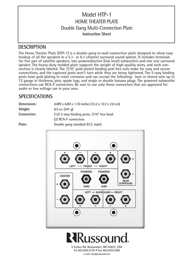
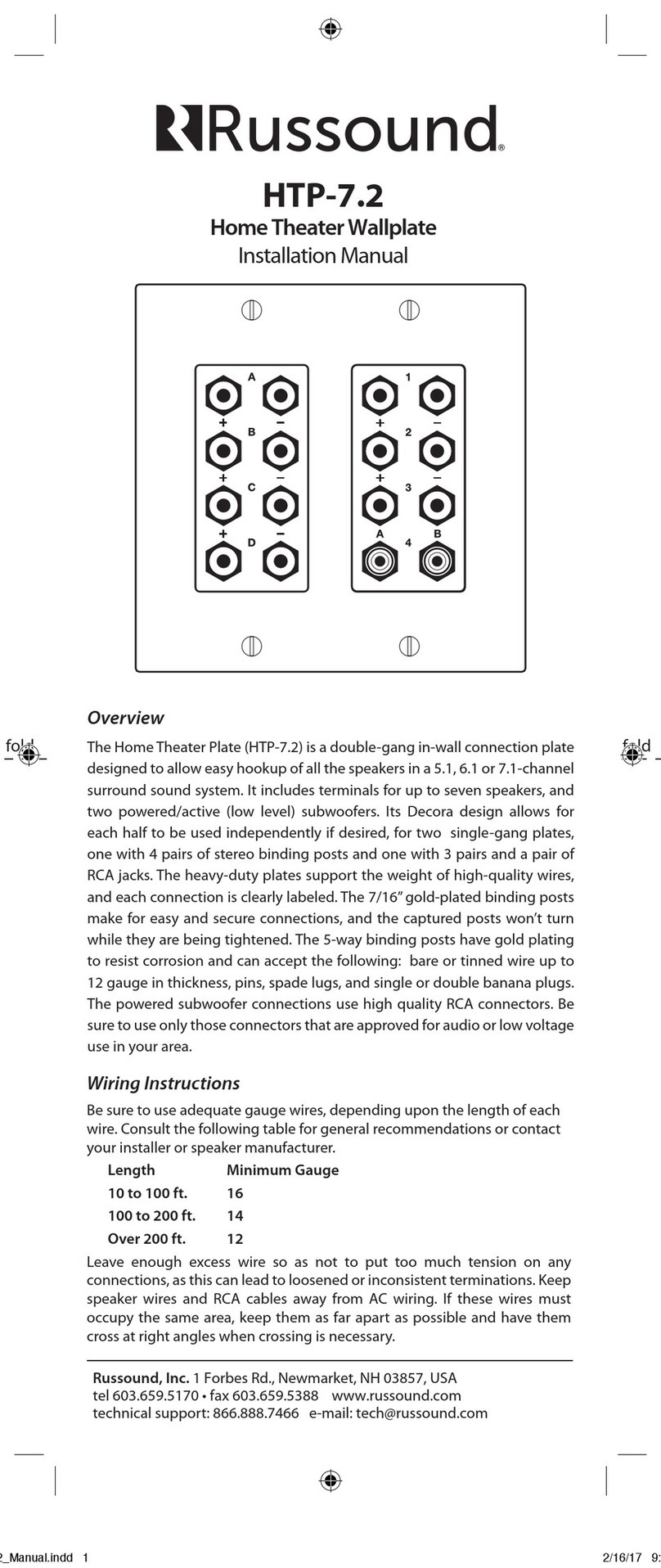
Russound HTP-1 User manual

Russound

Russound HTP-1 User manual

Russound IRB-1 User manual

Russound

Russound IRB-1 User manual

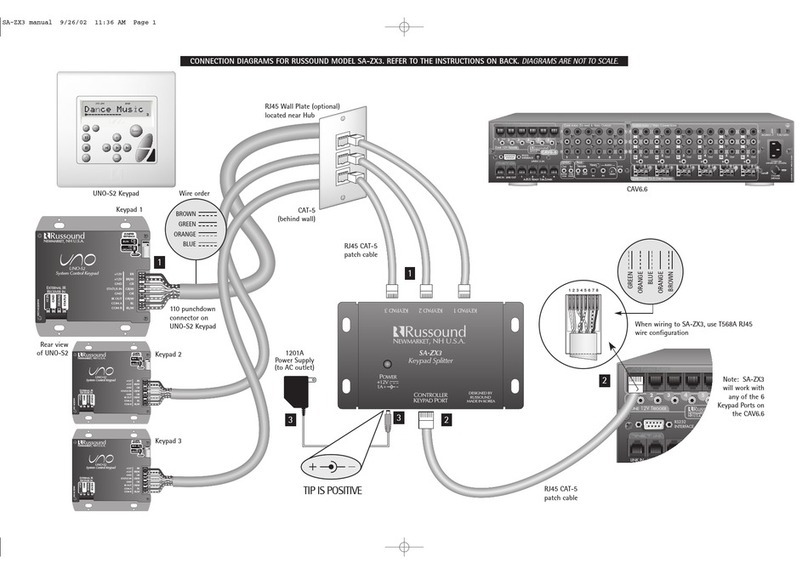
Russound SA-ZX3 User manual

Russound

Russound SA-ZX3 User manual

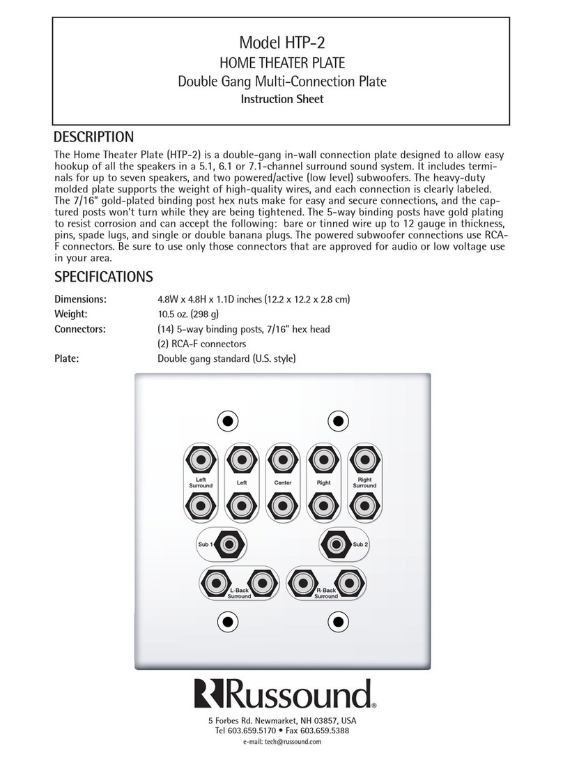
Russound HTP-2 User manual

Russound

Russound HTP-2 User manual

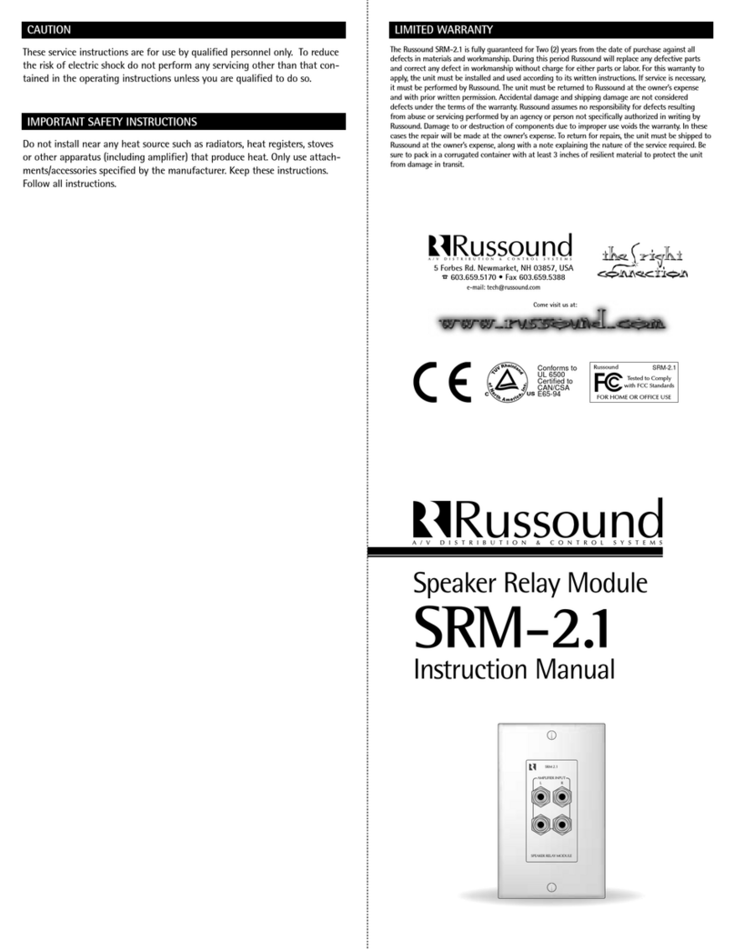
Russound SRM-2.1 User manual

Russound

Russound SRM-2.1 User manual

Russound SA-ZX3 - DIAGRAM Technical manual

Russound

Russound SA-ZX3 - DIAGRAM Technical manual

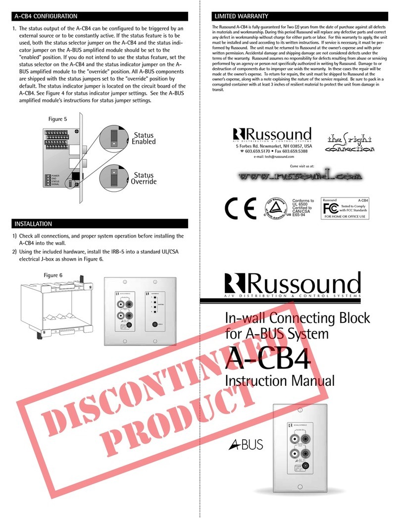
Russound A-CB4 User manual

Russound

Russound A-CB4 User manual

Russound HTP-7.2 User manual

Russound

Russound HTP-7.2 User manual

Russound IRB-6 User manual

Russound

Russound IRB-6 User manual

Popular Cables And Connectors manuals by other brands

Hailink SP14HA10RK user manual

Hailink

Hailink SP14HA10RK user manual

Sealey POWER PRODUCTS PROJUMP PROJ12 instructions

Sealey

Sealey POWER PRODUCTS PROJUMP PROJ12 instructions

Novus NVG-031TLIB user manual

Novus

Novus NVG-031TLIB user manual

Allen-Bradley 1769 CompactLogix installation instructions

Allen-Bradley

Allen-Bradley 1769 CompactLogix installation instructions

Lincoln 83753 Installation and maintenance guide

Lincoln

Lincoln 83753 Installation and maintenance guide

Elation COMPU WARE 2004 user manual

Elation

Elation COMPU WARE 2004 user manual

Kyocera 5861 Series instruction manual

Kyocera

Kyocera 5861 Series instruction manual

RetroSound M2-FBC-1 installation guide

RetroSound

RetroSound M2-FBC-1 installation guide

Digitus DS-45337 Quick installation guide

Digitus

Digitus DS-45337 Quick installation guide

foxunhd FX-SP07S operating instructions

foxunhd

foxunhd FX-SP07S operating instructions

Cypress CHDMI-210T Operation manual

Cypress

Cypress CHDMI-210T Operation manual

Keysight Technologies 11667B Operating and service manual

Keysight Technologies

Keysight Technologies 11667B Operating and service manual

Tlian T4 installation manual

Tlian

Tlian T4 installation manual

GTV AE-BPW1U1UCH-51 manual

GTV

GTV AE-BPW1U1UCH-51 manual

Yamaichi Electronics Y-CON Cover-40-PP Assembly instructions

Yamaichi Electronics

Yamaichi Electronics Y-CON Cover-40-PP Assembly instructions

Kikusui SC01-PFX instruction manual

Kikusui

Kikusui SC01-PFX instruction manual

Philips SWR1231 Specifications

Philips

Philips SWR1231 Specifications

EVAX 6670 Wiring instructions

EVAX

EVAX 6670 Wiring instructions

manuals.online logo
manuals.online logoBrands
  • About & Mission
  • Contact us
  • Privacy Policy
  • Terms and Conditions

Copyright 2025 Manuals.Online. All Rights Reserved.