Rutenbeck TC IP 1 User manual

TC IP 1
Operating nstructions

2
The TC P 1 allows the switching
of electrical devices via the
TCP/ P-network. The device is lo-
cated in a plug-plug adapter
housing.
To put into operation the TC P 1
simply has to be connected to a
power outlet and the respective
network.
The device to be switched will
plugged into the provided power
outlet of the TC P 1. The TC P 1
can be switched from all compu-
ters of the same network with
their web browser by P-address
192.168.0.2.
The TC P 1 can also be opera-
ted from the nternet if certain
preconditions are fulfilled.
A local operation is possible with
a push-button on the device.
The actual switching state of the
output is indicated by a LED at
the push-button for switching.
With a web browser it is possible
to display the actual temperature
at connected temperature sensor
(optional, article number:
700 802 201) as well as the set-
tings of the network characteris-
tics and the time switch.
System Requirements
The homepage has been optimi-
sed for the E 7. JavaScript must
be activated at your browser.
Overview
TC P 1 700 902 610
Operating instructions
Figure 1
Table of Contents
General ..........................................................................................................................................2
Configuration .................................................................................................................................3
System Settings without DHCP-Server . . . . . . . . . . . . . . . . . . . . . . . . . . . . . . . . . . . . . . . . . . . . . . .3
System Settings with DHCP-Server . . . . . . . . . . . . . . . . . . . . . . . . . . . . . . . . . . . . . . . . . . . . . . . . . .3
mpulse Mode . . . . . . . . . . . . . . . . . . . . . . . . . . . . . . . . . . . . . . . . . . . . . . . . . . . . . . . . . . . . . . . . .4
Switching Function . . . . . . . . . . . . . . . . . . . . . . . . . . . . . . . . . . . . . . . . . . . . . . . . . . . . . . . . . . . . .4
Factory Settings . . . . . . . . . . . . . . . . . . . . . . . . . . . . . . . . . . . . . . . . . . . . . . . . . . . . . . . . . . . . . . .5
Operating Elements . . . . . . . . . . . . . . . . . . . . . . . . . . . . . . . . . . . . . . . . . . . . . . . . . . . . . . . . . . . . .5
Switching of the TC IP 1 via the internet .......................................................................................6
Procedure . . . . . . . . . . . . . . . . . . . . . . . . . . . . . . . . . . . . . . . . . . . . . . . . . . . . . . . . . . . . . . . . . . . .6
Switching of the TC IP 1 with your mobile phone ..........................................................................6
Troubleshooting .............................................................................................................................6
Technical Data ...............................................................................................................................7
Manufacturer’s arranty................................................................................................................7
Service . . . . . . . . . . . . . . . . . . . . . . . . . . . . . . . . . . . . . . . . . . . . . . . . . . . . . . . . . . . . . . . . . . . . . .7
Manufacturer’s Declaration............................................................................................................7
Disposal of aiste .........................................................................................................................7
Scope of Delivery Accessory (optional)
Temperature sensor 700 802 201
Push-button on/off
(plug adapter)
Push-button reset
LED link/activity
LED plug adapter on/off
General
network access
access for temperature sensor
plug adapter
2

System Settings with DHCP-Server
3
System Settings without DHCP-Server
1 Connect the TC P 1 with a
patch cord (separately deli-
verable) to the local network.
2 Connect the temperature
sensor (optional) at the spring
terminals.
3 Push the TC P 1 in a plug.
4 The TC P 1 can be reached
with a browser entering the
address http://192.168.0.2
or http://TC P1.
5 With the button „network con-
figuration“ in the main menu
(arrow, figure 2) you will ac-
cess the system settings of
TC P 1 (figure 3).
6 n order to call up the TC P1
directly, choose under “Net-
work name” an individual
name.
7 Modify the P-address of the
TC P 1 according to your
own needs.
8 ncrease the access pro-
tection of your network con-
nection through an individual
user name and password.
Once a password has been
chosen, the user name and
password will be required to
have access to the website.
Three categories are possi-
ble:
· f neither “administrator
name” nor “user name” has
been saved, everyone has
full access to all functions.
· f an “administrator name”
has been saved but no
“user name”, everyone can
access the website and per-
form the manual switching
functions. The “network
configuration” can only be
done from the administrator.
· f an “administrator name”
and a “user name” have
been saved, the “administra-
tor” and the “user” can ac-
cess the website and
perform the manual swit-
ching functions. The “net-
work configuration” can only
be done from the adminis-
trator.
9 With “send” the configuration
will be saved.
Figure 2
Figure 3
1 Connect the TC P 1 with a
patch cord (separately deli-
verable) to the local network.
2 Connect the temperature
sensor (optional) at the spring
terminals.
3 Push the TC P 1 in a plug.
4 The TC P 1 can be reached
with a browser entering the
address http://192.168.0.2
or http://TC P1.
5 With the button „network con-
figuration“ in the main menu
(arrow, figure 2) you will ac-
cess the system settings of
TC P 1 (figure 3).
6 n order to call up the TC P1
directly, choose under “Net-
work name” an individual
name.
7 Now activate the DHCP-ser-
ver (arrow, figure 3).
8 Proceed as described above
under points 8 and 9.
10 The TC P 1 will be assigned
a free P-address.
3
Configuration

Switching Function
4
Impulse Mode
The output can be switched in
impulse mode if needed. t will
be distinguished between two
kinds of impulses. The on-im-
pulse switches on the output for
the selected time and the off-im-
pulse switches off the output for
the selected time.
f the output is already switched
on while sending an on-impulse,
“ mpulse time activated!” will be
displayed in a window (figure 5).
Click on „OK” and it will be swit-
ched off after passing the im-
pulse time. The light bulb on the
website indicates the actual swit-
ching state.
The TC P 1 has an integrated
time switching function. Up to 4
switching on and 4 switching off
times can be selected.
At any one time one switching on
time is combined in a group with
a switching off time. The days of
a week can be allocated to each
group.
n the above example (figure 6) a
laser printer of a company is
connected at the TC P 1. The
printer will be switched on from
Monday to Friday at 8 o’clock in
the morning and switched off a
12 o’clock. After the lunch break
the printer will be switched on
again at 13 0clock and switched
off at 17 o’clock. On Fridays the
printer will be turned on at 8
o’clock in the morning and swit-
ched off at 13:30 o’clock. On
weekends is the printer not in
use. f the printer is needed out-
side the programmed times, the
user is able to switch the printer
on at any time either with the
built-in push-button or from the
website.
The system time is the
actual time of the PC.
With activation of the
button “time switching
function accepted”, the system
time of the PC will be stored in
the TC P 1. The system time will
be updated every second. The
internal time of the TC P 1 will
be buffered up to 4 days after
disconnecting from the mains
power supply. n order to avoid
unnecessary traffic on the net-
work, the display with the time of
the TC P1 will only be updated
all 30 seconds.
Figure 6
Configuration
Figure 4 Figure 5
4

5
Configuration
Switching functions, which over-
lap from one day to the other, are
also possible. The example (fi-
gure 7) shows the settings for
the lighting of a shop window.
The lighting is to be switched on
daily at 17:00 o’clock. From
Monday to Friday the lighting has
to be switched off at 7 in the
morning. On the weekends – Sa-
turday and Sunday- it has to be
switched off already at 1 o’clock.
n this example only one swit-
ching-on or switching-off time is
activated in a group.
The factory settings of the deli-
very state can be replaced with
individual settings. n order to re-
load the factory settings, unplug
the TC P 1. Push both push-but-
tons of the device and insert the
device with the pushes buttons
in a power outlet. After about 3
seconds the LED starts blinking
to indicate that the factory set-
tings have been restored.
Figure 7
on/off: Switches the connected
devices directly on or off.
L/A: By pressing both push-
buttons (on/off and L/A)
the factory settings will
be restored (see above).
on/off: This LED indicates the
switching state of the
connected device. t
lights up if the con-
nected device is swit-
ched on.
L/A: This LED indicates the
link and activity of the
network connection. The
LED flashes , if a user
has accessed the home.
Push-buttons
Operating Elements
Factory Settings
LEDs
The power outlet of the TC P 1
can be switched directly with the
integrated push-button or from
the website of the TC P 1.
A connected temperature sensor
displays the actual temperature
on the website.
Switching Function
5

Troubleshooting
The TC P 1 can be operated
from the nternet, if certain pre-
conditions are fulfilled.
Every time you login to the nter-
net, you start a new session and
receive from your provider an P-
address.
Through this P-address your
local network or PC can be iden-
tified from the internet for the
time of the connection to the in-
ternet. With each new session
you also receive a new P-ad-
dress.
Permanent connections, i.e. in
case of a flatrate, will be auto-
matically disconnected after max.
24 hours and established again
with a new P-address (dynamic
P). n order to always access the
TC P 1 or another P-device with
the same address from the inter-
net, additional mechanism must
be activated. The TC P 1, re-
spectively, the P-device receives
a so called hostname (freely se-
lectable) which allows the device
to be found from the internet. A
provider translates the hostname
to the valid P-address during the
actual session.
Following are necessary:
· A DNS-server (provider) for the
translation of the dynamic P in-
to a host-name, i.e. free of
charge provider DynDNS
(www.dyndns.com).
· Optionally additional software
to ensure, that after an inter-
ruption of a session, the trans-
lation will be done again. This
software is also free of charge
and also available at the provi-
der (i.e. “DynDNS-updater” un-
der www.dyndns.com ). Up-to-
date router and telephone sys-
tems perform this translations
by themselves.
· The configuration of the router
for the access in a local net-
work.
1 Register at a dynamic DNS-
server of your choice.
2 Define a Hostname. Choose
a name that is easy to re-
member to make the dial-in
from the internet as easy as
possible.
3 nstall, if required, the additio-
nal software (DNS update
client) on at least one PC wit-
hin the network to be acces-
sed. t is even better, if you
install the software on all PCs
that have access to the inter-
net. This guarantees that with
each connection of any PC to
the internet, the address
translation will automatically
be done.
4 Configure your router. First,
the corresponding port num-
ber for the remote access
must be defined and opened.
The router must know that te-
legrams must be directed to
the TC P 1 within the local
network via the requested
port number. The TCP-proto-
col is being used for the ope-
ration of the TC P 1, which
should be directed to the ad-
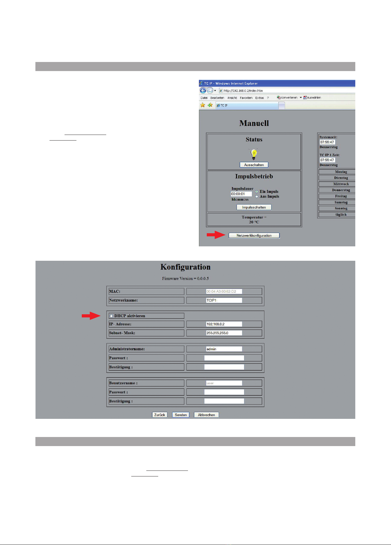
dress of the TC P 1 (default-
address of the TC P 1 =
192.168.0.2). n general, port
80 is being used at http.
This configuration will be
done at the DMRM from Ru-
tenbeck under item “virtual
server”. The port can be con-
figured at the KRR from Ru-
tenbeck as follows:
Firewall-Status
l
User defined
l
nternal Host
l
WAN-Port/LAN-Port
Switching of the TC IP 1 with your mobile phone
Procedure
Switching of the TC IP 1 via the internet
6
The TC P 1 can be operated
from your mobile phone, if this
supports JavaScript.
Furthermore, all preconditions for
the switching from the internet
must be fulfilled.
Fault Help/Measure
Testing of the switching function Press the On/Off-push-button
The LED L/A does not light up
after the connection of the net-
work patch cable
Check the network connection//patch cable
The TC P 1 can not be switched
via the network
Use an P-address that belongs to the subnet (the first three number blocks of the P-address must be
identical).
Check the network settings. Enter the command „ipconfig/all“under „Start/Programs/Accessory/Com-
mand prompt”.
Switch off the Proxy-Server for local adresses
At the nternet Explorer: Type in an exception under „Extra/ nternet options/Connections/Lan-Connecti-
ons/Extended“ for the P-address of the TC P 1 (i.e. 192.168.0.2).
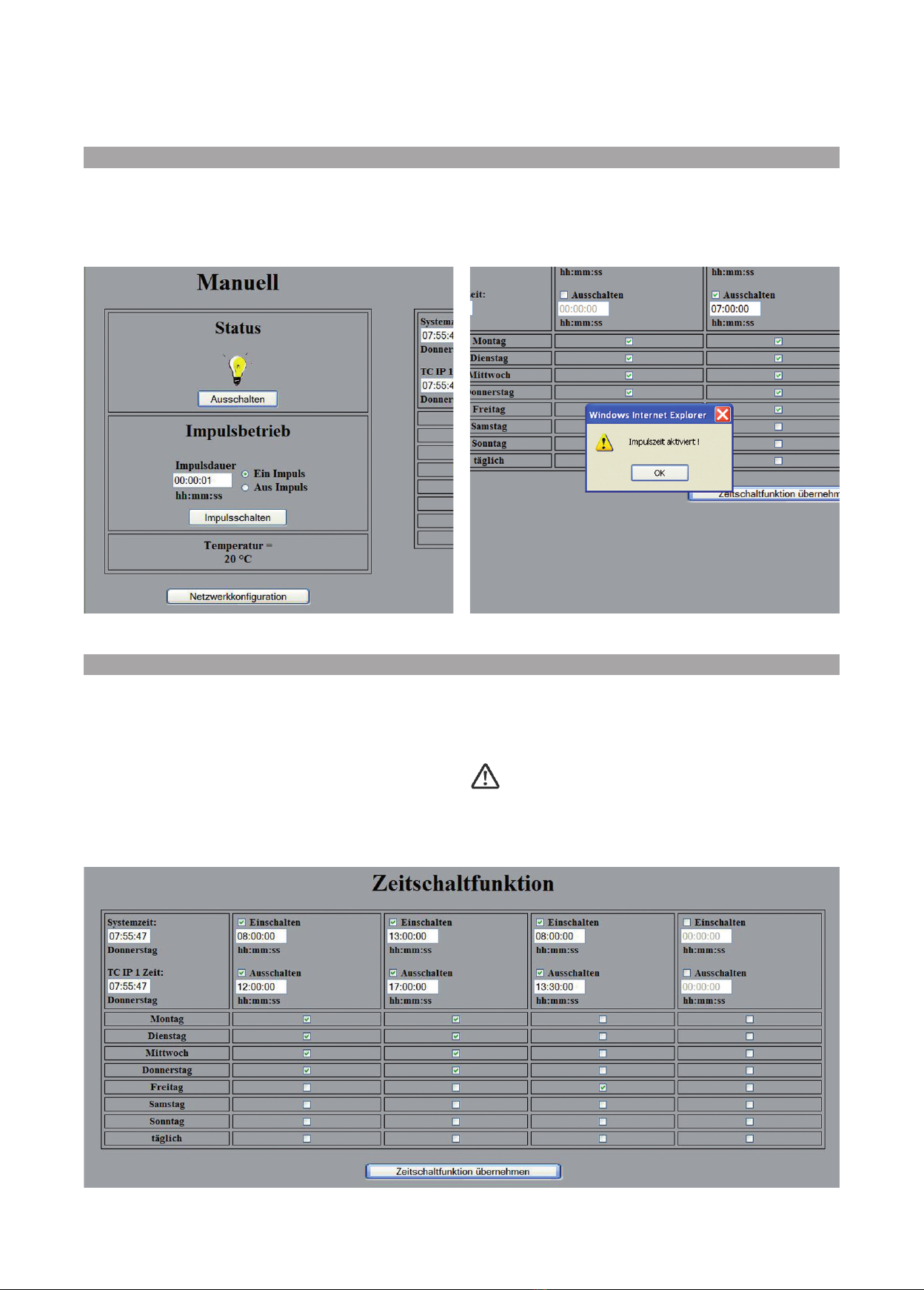
Switching times will not be execu-
ted as programmed
Check the time of the TC P 1

Disposal of aiste
Dimensions L x B x H:
Material:
Weight:
Color:
Temperature range
Operation:
Storage:
Protection class:
Power supply:
Switching capacity:
Current consumption
output switched off, with network:
output switched on, with network:
Max. buffer time of settings:
Accesses
Network access
Temperature sensor (optional)
Article number:
Length:
Extension:
Temperature range:
Temperature drift
-25 °C:
25 °C:
50 °C:
B value:
135 x 66 x 75.7 mm
ABS VO (flame-retardant)
170 g
pure white (similar RAL 9010)
-20 to 55 °C
-25 to 70 °C
P20 according to EN 60529
100–240 V AC/50–60 Hz
max. 250 V AC/50–60 Hz/16 A
app. 1 W
app. 1.6 W
app. 4 days (after cutting off from 230 V)
RJ45, 10 Mbit/s
700 802 201
0.6 m
to max. 10 m
-25–55 °C, resolution 1 °C
86.4 kΩ
10 kΩ
4.1 kΩ
3435 K ±1%
7
n case of a malfunction consult
the expert who installed the TC
P 1 or send it with the receipt an
a short description of the mal-
function to the following address:
Rutenbeck Service-Center
Gewerbegebiet
Im Meilesfelde 5
99819 Marksuhl
Germany
Phone +49 36925 90091
Fax +49 36925 90092
We guarantee the perfect func-
tion of the TC P 1 for 2 years
after date of purchase (receipt)
assuming that it was profession-
ally installed and operated.
We, Wilhelm Rutenbeck GmbH &
Co. KG declare, that the TC P 1
was manufactured under a full
quality assurance system and
that the mentioned equipment is
in compliance with the essential
requirements and provisions of
the directives 2004/108/EG und
2006/95/EG.
The complete declaration of
conformity can be found
under www.rutenbeck.de in the
download-sector.
Please do your part to
protect the environ-
ment by properly re-
cycling this
equipment at a col-
lection point in the
community for the disposal of
electronic equipment according
to the European Directive
2002/96/EG.
Please consult your local authori-
ties.
You should never dispose of this
device in general unsorted
garbage.
mproper disposal of electronic
waste can introduce dangerous
substances into the environment
and affect public health.
The recycling system will be fi-
nanced since August 13, 2005
by manufacturers of electrical
and electronic equipment.
Manufacturer’s Declara-
tion
Service
Manufacturer’s arranty
Technical Data

© Rutenbeck Telecommunication 2010 · 20191201 · Status 10/10 · Subjected to technical changes
Niederworth 1–10
58579 Schalksmühle
Germany
Phone +49 2355 82-0
Fax +49 2355 82-105
www.rutenbeck.de
Table of contents
Other Rutenbeck Accessories manuals