Installation Installation
hinter dem Blech der Trägerplatte ein und rasten
es nach unten fest.
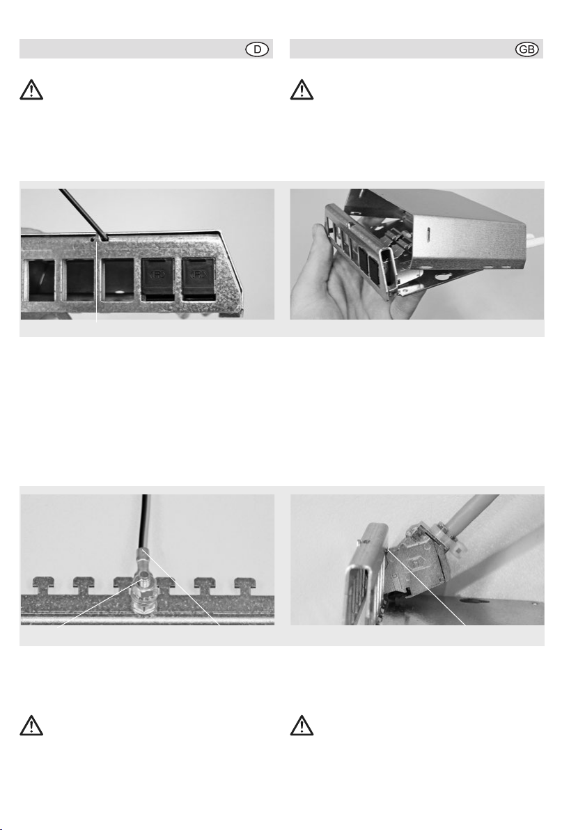
Kabel befestigen
Berücksichtigen Sie den finalen Montageort bei
der Wahl der Datenkabellängen. Befestigen Sie
die Kabel einzeln mit z.B. Kabelbindern (E).
Modul lösen
Stecken Sie den Schraubendreher von unten,
mittig vom jeweiligen Modul, hinter die Einschub-
blende (F) und drücken Sie die Rastnase des
Moduls schräg nach oben.
Lösen Sie die ggf. schon vorhandene Kabelbinder.
Wichtiger Hinweis!
Die Anschlusskomponenten ab Category 6A sind
elektrisch und mechanisch hoch entwickelte
Stecksysteme für Übertragungsbandbreiten bis
500 MHz. Sie erfüllen die aktuellen Normen für
die Bauform sowie die Übertragungstechnik und
die entsprechenden internationalen Festlegungen
in vollem Umfang. Um die Leistungsfähigkeit im
Praxiseinsatz garantieren zu können, sind auch
die gleichen Anforderungen an die eingesetzten
Stecker/Patchkabel zu stellen!
Verwenden Sie deshalb ausschließlich Patchkabel
mit Steckern, die gemäß Herstellerangaben den
gültigen EN/IEC-Normen entsprechen!
Bei der Vielfalt der Hersteller im Markt und unter-
schiedlichen Qualitätslagen ist die erforderliche
Normkonformität leider nicht bei allen Produkten
selbstverständlich!
Dies gilt für die messtechnische Überprüfung, vor
allem bei herstellerspezifischen Permanent-Link-
Adaptern, wie für den Alltagsbetrieb. Ein hoch-
wertiges Hochfrequenzstecksystem sollte auch
mit der gebotenen Sorgfalt bedient werden.
Bei Verwendung nicht normgerechter Anschluss-
komponenten müssen wir von einer Anerkennung
the face plate of the base and push down to click
it in place.
Fastening the cables
Take the length of the data cables into account
when choosing the final installation location. Fas-
ten each cable in place separately using cable ties
(E), for example.
Removing modules
Insert the screwdriver from the bottom in the mid-
dle of the corresponding module behind the open-
ing (F) and press the retaining tab of the module
upwards at an angle.
If necessary, remove the cable tie.
Important Information!
The connection components in Category 6A and
higher are electrically and mechanically highly
developed connector systems for transmission
bandwidths of up to 500 MHz. They comply fully
with the current design standards and transmis-
sion technology standards as well as the corre-
sponding international specifications. To ensure
the best possible performance in actual use, the
connectors and patch cables used should meet
the same requirements!
For this reason, only use patch cables with con-
nectors conforming to the currently valid EN/IEC
standards according to the manufacturer‘s spec-
ifications!
Due to the diversity of the manufacturers on
the market and various levels of quality, not all
products will necessarily conform to the required
standards!
This applies when taking measurements, espe-
cially with manufacturer-specific permanent link
adapters, as well as during daily operation. Appro-
priate care should also be taken when operating
a high-quality, high-frequency connector system.
We do not recognize any rights regarding defects
or other guarantees provided by our company
3
E F