Rutenbeck POF/UAE 1xUp 0 User manual

In case the POF-cable is supposed to
be put in empty cable ducts together
with the electrical installation or in case any
other operations on the electrical installation
will be necessary, note, that this work must
be performed exclusively by autho-rized and
experienced professionals.
Installation of power supply
Disconnect the main voltage at first for
all mounting works.
Danger for life!
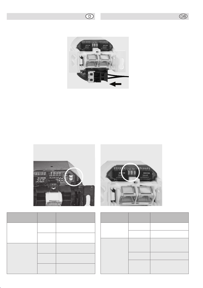
Connect the mains voltage to the
terminals L
and N ( the figure shows a view
of the converter from the back).
Cutting and connecting the
POF-cable
After having laid the POF-cable
(corresponding hints can be
found under www.rutenbeck.de
in the dowload-sector) shorten it
as described below:
1. Pull the cable through the installation box and
shorten the fibres to approx. 190 mm.
Only use junction-boxes!
2. Cautiously split the cable down the middle for
approx. 30 mm and make sure that there is no
unevenness on the coating which could hinder
the inserting of the cable.
3. Insert the cable into the POF cutting tool and cut
it by pressing the blade.
4. Make sure that both wires are equally long.
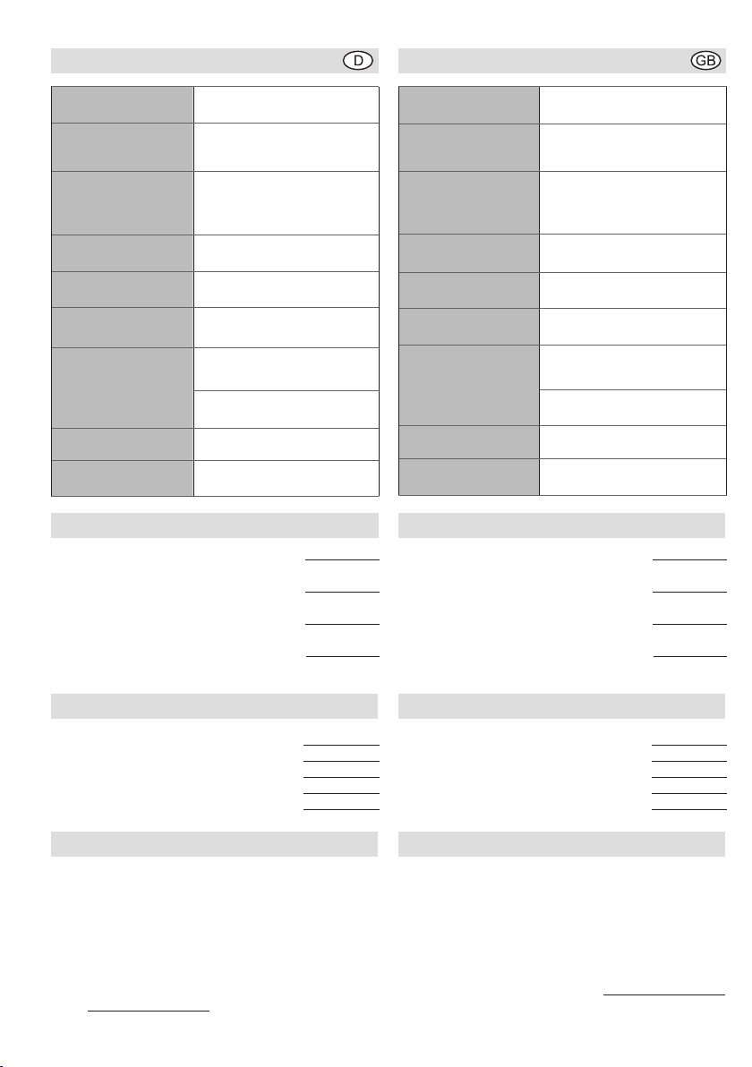
5. Open the POF terminal by slightly pulling it out
and remove the red protection cap.
Wenn das POF-Kabel zusammen mit der
Elektroinstallation in Leerrohre eingezo-
gen werden soll oder sonstige Eingriffe in die
Elektroinstallation notwendig werden, beach-
ten Sie bitte, dass diese Arbeiten nur von
einem autorisierten Fachmann ausgeführt
werden dürfen!
Anschließen der Netzspannung
Schalten Sie die Netzspannung vor dem
Anschließen frei.
Lebensgefahr!
Schließen Sie die Netzspannung
an die Klemmen L und N an (Bild
zeigt die Ansicht des Konverters
von hinten).
Zuschneiden und Anschließen
des POF-Kabels
Nach dem Verlegen des POF-
Kabels (Hinweise hierzu finden
Sie unter www.rutenbeck.de im
Downloadbereich) gehen Sie fol-
gendermaßen vor:
1. Ziehen Sie das Kabel in die Schalter- oder Kanal-
einbaudose ein und kürzen Sie die Leiter auf ca.
190 mm.
Verwenden Sie ausschließlich Geräte-Verbin-
dungsdosen!
2. Trennen Sie das Kabel in der Mitte ca. 30 mm
vorsichtig auf und achten Sie darauf, dass
keine Unebenheiten des Mantels das Einführen
des Kabels behindern können.
3. Führen Sie es in das POF-Schneidewerkzeug
ein und schneiden Sie es durch Druck auf die
Klinge ab.
4. Achten Sie darauf, dass beide Adern gleich
lang sind.
5. Öffnen Sie die POF-Klemme durch leichtes
Ziehen am schwarzen Anschluss und entfernen
Sie die rote Schutzkappe.
POF-Cable Adapter
POF/UAE 1xUp 0, POF/UAE 2xUp 0
Installationsanleitung Installation instructions
POF-Up-Medienkonverter
POF/UAE 1xUp 0, POF/UAE 2xUp 0
NL
Erdleiter ground wire

6. Anschließend setzen Sie den Up-Medienkon-
verter in die Dose ein und befestigen ihn mit
Hilfe der Tragstege.
7. Führen Sie das POF-Kabel ein
und achten Sie darauf, dass
es bis zum Anschlag gescho-
ben wird, um eine sichere
Verbindung zu gewährleisten.
8. Schließen Sie die POF-Klem-
me, indem Sie den schwarzen
Anschluss zum Fixieren des
Kabels in die Geräteöffnung
schieben.
9. Schalten Sie die Netzspannung an.
10. Schließen Sie Ihre Ethernet-Geräte (z. B. PC,
Router, Set-Top-Box) über Patchkabel an den
RJ45-Anschlüssen an.
Die LEDs auf den Geräten (weißer Kreis) zeigen
folgende Zustände an:
6. Place the flush-mounting media converter in the
installation box and fasten it with the help of the
mounting brackets.
7. Insert the POF-cable. Make sure
that it is pushed all the way up to
the stop in order to guarantee a
safe connection.
8. Close the POF terminal by
pushing it into the open-ing of the
device thus fastening the cable.
9. Connect the power supply.
10. Connect your Ethernet devices (PC, router, set
top box e. g.) up to the RJ45 terminal jack via the
enclosed patch cables.
The LEDs on the devices (white circle) show the
following states:
Variante LED Zustand
POF/UAE 1xUp unten optischer Link
oben Ethernet-Link
POF/UAE 2xUp links Ethernet-Link,
linke Buchse
Mitte optischer Link
rechts Ethernet-Link,
rechte Buchse
POF/UAE 1xUp POF/UAE 2xUp
version LED status
POF/UAE 1xUp bottom optical link
top Ethernet link
POF/UAE 2xUp left Ethernet link left ter-
minal jack
middle optical link
right Ethernet link right
terminal jack

Power supply 100 - 240 V ±10 %
Max. current consump.
POF/UAE 1xUp 0
POF/UAE 2xUp 0
30 mA
50 mA
Power consumption
typical
POF/UAE 1xUp 0
POF/UAE 2xUp 0
0,9 W
1 W
Operating
temperature -5 to +45 °C
Transmission rate
100 Mbit/s
Transmission length 50 m with POF 1.5 mm
70 m with POF 2.2 mm
Data connection
electrical
optical
RJ45
1.5 mm Duplex POF/
2.2 mm Duplex POF
Wave length 660 nm typical
Protection Class IP20 according to
EN 60529
Spannungsversor-
gung 100 - 240 V ±10 %
max. Stromaufnahme
POF/UAE 1xUp 0
POF/UAE 2xUp 0
30 mA
50 mA
Leistungsaufnahme
typisch
POF/UAE 1xUp 0
POF/UAE 2xUp 0
0,9 W
1 W
Betriebstemperatur -5 bis +45 °C
Übertragungs-
geschwindigkeit 100 Mbit/s
Übertragungslänge 50 m mit POF 1,5 mm
70 m mit POF 2,2 mm
Datenanschluss
elektrisch
optisch
RJ45
1,5 mm Duplex POF/
2,2 mm Duplex POF
Wellenlänge 660 nm typisch
Schutzart IP20 gemäß
DIN EN 60529
Technische Daten Technical Data
POF/UAE 1xUp 0 1,5 mm
oder
POF/UAE 1xUp 2,2 0 mm
oder
POF/UAE 2xUp 0 1,5 mm
oder
POF/UAE 2xUp 0 2,2 mm
Installationsanleitung
180 104 02
180 104 03
180 104 06
180 104 07
293 616
Lieferumfang Scope of Delivery
POF/UAE 1xUp 0 1,5 mm
or
POF/UAE 1xUp 2,2 0 mm
or
POF/UAE 2xUp 0 1,5 mm
or
POF/UAE 2xUp 0 2,2 mm
Installation instructions
180 104 02
180 104 03
180 104 06
180 104 07
293 616
50-m-Ring POF-Kabel, 1,5 mm 180 000 00
500-m-Spule POF-Kabel, 1,5 mm 180 000 01
500-m-Spule POF-Kabel, 2,2 mm 180 000 02
ZSt UAE 8 130 100 02
AP 100 100 01
Zubehör (optional) Accessory (optional)
50-m-Ring POF-Kabel, 1,5 mm 180 000 00
500-m-Spule POF-Kabel, 1,5 mm 180 000 01
500-m-Spule POF-Kabel, 2,2 mm 180 000 02
ZSt UAE 8 130 100 02
AP 100 100 01
Wir, die Wilhelm Rutenbeck GmbH & Co. KG,
erklären in alleiniger Verantwortung, dass die POF/
UAE-Up-Produkte gemäß eines zertifizierten,
umfassenden Qualitätssicherungssystems herge-
stellt wurden und sich in Übereinstimmung mit den
Anforderungen und Vorschriften der Richtlinien
2004/108/EG und 2006/95/EG befinden.
Die vollständige Konformitätserklärung finden Sie
unter www.rutenbeck.de im Downloadbereich.
We, Wilhelm Rutenbeck GmbH & Co. KG, declare
in our sole responsibility, that the POF/UAE Up
devices were manufactured under a full quality
assurance system and that the mentioned equip-
ment are in compliance with the essential require-
ments and provisions of the directives 2004/108/
EG und 2006/95/EG. The complete declaration of
conformity can be found under www.rutenbeck.de
in the download-sector.
Herstellererklärung Manufacturer‘s Declaration

Niederworth 1-10
58579 Schalksmühle
Telefon (0 23 55) 82-0
Telefax (0 23 55) 82-105
www.rutenbeck.de
Bei technischen Fragen:
Rutenbeck Servicecenter
Hotline (03 69 25) 9 00 90
Telefax (03 69 25) 9 00 92
© Wilhelm Rutenbeck GmbH & Co. KG 2009 · Technische Änderungen vorbehalten/Subjected to technical changes · 293 616 (10311301) Stand/Status 02.12
This manual suits for next models
1
Other Rutenbeck Cables And Connectors manuals
Popular Cables And Connectors manuals by other brands

Staubli
Staubli MC4-Evo 2 PV-K/SPL-Y Installation and operation manual

Konig
Konig CMP-REPEATVGA3 manual

National Instruments
National Instruments IMAQ D100DAL installation guide

Gefen
Gefen GTB-HD4K2K-142C-BLK user manual

RIDGID
RIDGID SeeSnake NanoReel Operator's manual

Philips
Philips SWV3535 Specifications