Beachten Sie bitte auch die zulässige Betrieb-
stemperatur, setzen Sie den POF/UAE 1xUp nicht
direkt neben Geräten mit hoher Wärmeentwick-
lung (z. B. Dimmer) ein.
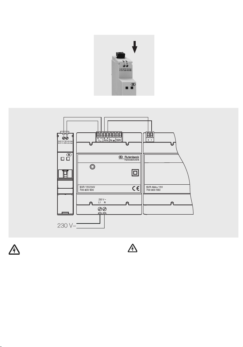
1 Schließen Sie die SVR 12/24 V an den POF/
UAE 1xPPR an, indem Sie die Anschlussklem-
men Uaus (+ und -) des SVR 12/24 V durch ein
Installationskabel mit „+“ und „-“ des POF/UAE
1xPPR verbinden.
2 Falls erforderlich schließen Sie die Leitungen
zum Akku an, z. B. wie auf dem Bild gezeigt.
3 Schließen Sie die Klemmen L1 und N der SVR
12/24 V an das 230-V-Versorgungsnetz an.
Die grüne Betriebsanzeige leuchtet bei ange-
schlossener 230-V-Versorgung.
4 Sichern Sie die Stromversorgung über eine ei-
gene Sicherung in der Verteilung ab.
5 Schalten Sie die Netzspannung an.
6 Öffnen Sie die Staubschutzklappe und schlie-
ßen Sie Ihr Ethernet-Gerät (z. B. PC, Router,
Set-Top-Box) über Patchkabel am RJ45-An-
schluss an.
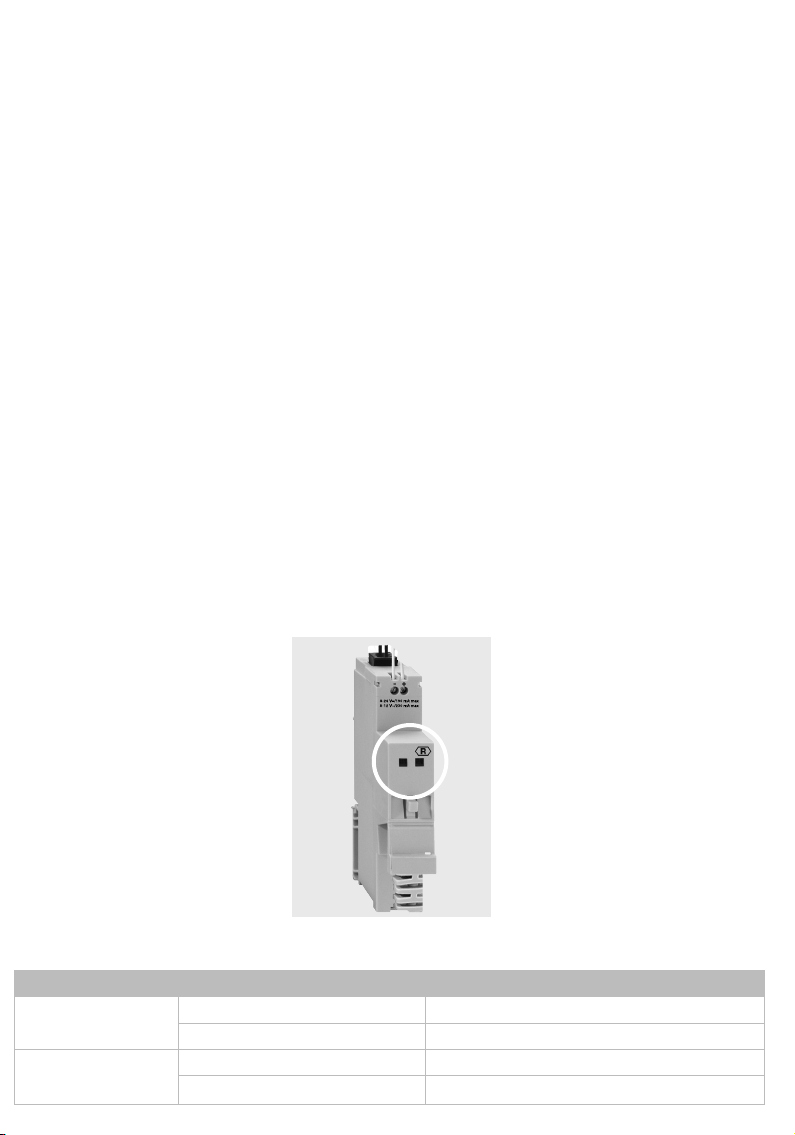
Die LEDs auf dem Gerät (weißer Kreis) zeigen fol-
gende Zustände an:
Please also observe the permitted operating
temperature, do not place the switching system
directly beside devices with high heat evolution
(e.g. dimmer).
1 To install the SVR 12/24 V to the POF/UAE
1xPPR, connect the terminal Uout (+ and -) of
the SVR 12/24 V by an installation cable with
˝+˝ and ˝-˝ of the POF/UAE 1xPPR.
2 If necessary, make all connections to the ac-
cumulator e. g. as shown in the figure.
3 Connect the 230 V-supply at the screw termi-
nal L1 and N. The green LED lights up when
the 230 V-supply is connected.
4 We recommend a seperate circuit breaker for
the power supply in the electrical distribution
box.
5 Connect The SVR 12/24 V with the power
supply.
6 Remove dust cover and connect your Ethernet
devices (PC, router, set top box e. g.) up to
the RJ45 terminal jack via the enclosed patch
cables.
The LEDs on the device (white circle) show the
following states:
5 Führen Sie das POF-Kabel ein
und achten Sie darauf, dass es
bis zum Anschlag geschoben
wird, um eine sichere Verbindung
zu gewährleisten.
6 Schließen Sie die POF-Klemme,
indem Sie den schwarzen An-
schluss zum Fixieren des Kabels
in die Geräteöffnung schieben.
Anschluss der Versorgungsspannung
Lebensgefahr durch elektrischen Strom!
Schalten Sie bei allen Montagearbeiten
zunächst die Netzspannung frei.
Achten Sie bei kombinierten Anlagen auf den
Berührungsschutz des Starkstromteils. Der Be-
rührungsschutz muss auch dann gewährleistet
sein, wenn Sie die gemeinsame Abdeckung ent-
fernt haben (dies ist bei Altanlagen nicht immer
gegeben).
Achten Sie bei der Errichtung kombinierter Anla-
gen auf die Einhaltung der Mindestabstände von
10 mm zwischen Daten-/Fernmeldeleitungen und
Starkstromleitungen.
Arbeiten an bestehenden Datennetzen bedürfen
ggf. der Zustimmung der jeweiligen Netzwerk-/
Datenbeauftragten sowie einer vorhergehenden
Datensicherung.
5 Insert the POF-cable. Make sure
that it is pushed all the way up to
the stop in order to guarantee a
safe connection.
6 Close the POF terminal by pushing
the black terminal into the opening
of the device thus fastening the
cable.
Connecting of the power supply
Danger for life!
Disconnect the main voltage at first for
all mounting works.
Pay attention to the shock-proof protection of the
heavy-current part in combined plants. The shock-
proof protection must also be guaranteed, when
you have removed the common covering
(this is not always given for old installations).
Take care that the minimum distance of 10 mm
between data-/ telecommunication cables and
heavy-current cables are strictly observed during
the erection of combined plants.
Working in existing data networks require – if
necessary – the assent of the respective person
in charge of network and data as well as a prece-
ding data security.
LED Zustand/status
links flackert/flashing Aktivität/activity
leuchtet/constantly Ethernet-Link/Ethernet link
rechts flackert/flashing Aktivität/activity
leuchtet/constantly optischer Link/optical link