7
systems from the on-board generator and the cooling demand
does not require that both systems operate, stage two will
shut down leaving stage one in operation. Heat operation
always energizes both stages, however, only stage one
operates if power is not available to circuit #2.
B. Thermostat
This thermostat is designed to operate 12 VDC controlled
heating and air conditioning systems. It can control one stage
of heating and two stages of cooling. It is a manual
changeover type of thermostat between heating and cooling.
Manual changeover indicates that the operator must manually
switch the thermostat from cooling operation to heating. The
thermostat will not make this change automatically. It also
incorporates time delay circuitry. The user selectable heating
mode on the sub-base allows gas heat control or heat pump
operation.
The time delays amount to 3 minutes between off and on
cycles. Thirty seconds of this time delay is at the turn on of
the compressors. This is to allow time for generators to
stabilize when initially starting. The balance of the delay (2.5
minutes) occurs when the compressors cycle off. This is to
allow time for the air conditioner pressures to balance before
restarting. This delay will eliminate problems associated with
short cycling and will extend equipment life. There is thirty
seconds and two degrees between 1st and 2nd stage cooling.
The thermostat will not call for 2nd stage cooling until room
temperature rises 2 degrees above the 1st stage starting
temperature. Once the thermostat calls for 2nd stage cooling, a
30 second delay is incurred to prevent both stages from
starting together.
The operating setpoints are changeable to suit the comfort
needs of the occupants. Instructions for setting operating
temperatures (the setpoints) are covered in “Adjusting
Setpoint”.
7. WALL THERMOSTAT - 6536-335*
A. APPLICATION
The 6536-335* thermostat is intended for use with an RV
Products 2 stage heat pump.
The thermostat connects to the heat pump with a 9 pin plug
through a lifeline (RVP part number 6795C4351). The OEM
(Original Equipment Manufacturer) must supply the 12 VDC
wiring and the furnace control wiring which connects to the 3
pin plug on the thermostat. The OEM supplies the mating
receptacle for the 3 pin plug. RV Products suggests the
thermostat wiring be minimum 18 gauge. The furnace control
circuit must not exceed 1 amp. The thermostat is equipped
with a replaceable fast-acting 2 amp fuse located on the base
of the thermostat. The fuse is designed to “open” if the
furnace is mis-wired or if there is a short in the system. Before
replacing fuse, the cause of the failure must be located and
corrected.
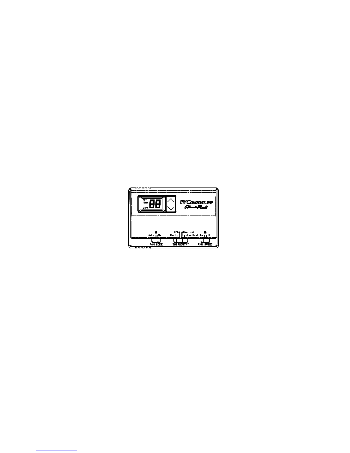
B. OPERATION
The display indicates room temperature and the word ROOM
is shown on the LCD until the temperature selector is pressed;
at which time the display temporarily indicates the setpoint
temperature and the word SET is shown on the LCD. Each
time the UP arrow is pressed, the setpoint will increase. Each
time the DOWN arrow is pressed, the setpoint will decrease.
Once the temperature selector button is no longer pressed for
a few seconds, the room temperature will again be displayed,
and the word ROOM will be displayed on the LCD.
In the electric heat mode, if the heat pump is unable to satisfy
the thermostat, the heat pump goes into lockout. DIFF will
display on the thermostat LCD indicating backup heating is
required to satisfy the thermostat.