RVE Merak E750 User manual

RVE Merak E750
Assembly Instructions
www.rverc.com
V1.0 FEB 2019

RVE MERAK E750 - ASSEMBLY INSTRUCTIONS
INTRODUCTION 4
ASSEMBLY RECOMMENDATIONS 4
MINIMUM REQUIRED TOOLS 5
OPTIONAL TOOLS 5
OTHER COMPONENTS REQUIRED 5
MAIN CHASSIS ASSEMBLY 6
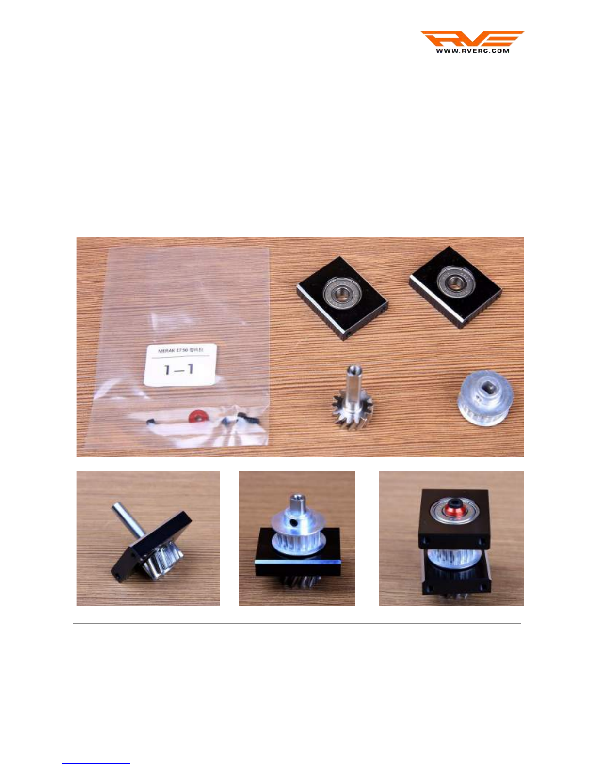
TAIL PINION BEARING BLOCK (1-1) 6
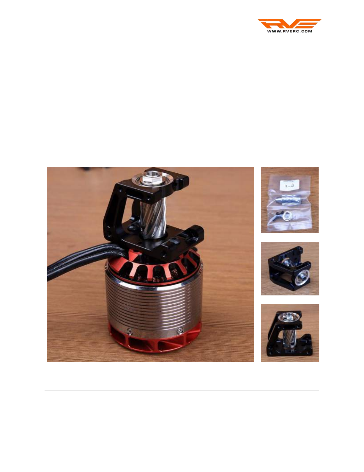
MOTOR BLOCK (1-2) 7
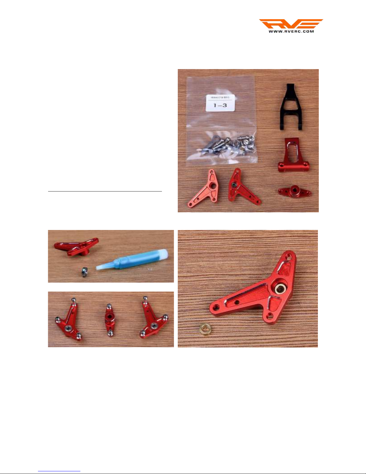
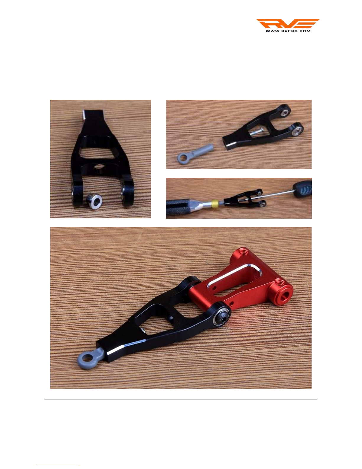
SWASH CONTROL LEVERS (1-3) 8
TAIL CONTROL LEVER (1-4) 10
ESC SUPPORT (1-6) 10
CONTROL LEVERS AND CABIN SUPPORT INSTALLATION (2-1) 11
MAIN MAST BEARING BLOCKS AND ELEVATOR LEVER INSTALLATION (2-2) 13
BATTERY TRAY SUPPORTS INSTALLATION (2-3) 15
SKID SUPPORTS INSTALLATION (2-4) 16
ESC SUPPORT INSTALLATION (2-5) 16
ELECTRONICS TRAY INSTALLATION (2-7) 17
SKID SUPPORTS REINFORCEMENT AND VIBRATION DAMPERS INSTALLATION (2-8,
2-9) 17
MAIN GEAR AND
AUTOROTATION BLOCK ASSEMBLY (3-1) 18
TAIL GEAR ASSEMBLY (3-2) 19
TAIL PINION BEARING BLOCK AND TAIL BOOM SUPPORT INSTALLATION (3-3) 20
MOTOR BLOCK INSTALLATION (3-4) 21
MAIN MAST AND GEARS INSTALLATION (3-5, 3-6) 21
MAIN ROTOR ASSEMBLY 23
SWASHPLATE ASSEMBLY (4-1) 23
PHASE ARM ASSEMBLY (4-2) 24
CENTER HUB ASSEMBLY (4-4) 25
BLADE HOLDER ASSEMBLY (4-6) 25
SPINDLE SHAFT AND BLADE HOLDERS INSTALLATION (4-5, 4-7) 26
MAIN ROTOR INSTALLATION (4-4) 27
TAIL ASSEMBLY 28
TAIL PULLEY ASSEMBLY (5-1) 28
2

RVE MERAK E750 - ASSEMBLY INSTRUCTIONS
TAIL CASE ASSEMBLY (5-2, 5-3, 5-4) 29
TAIL SLIDER ASSEMBLY (5-5) 30
TAIL PITCH LEVER ASSEMBLY AND INSTALLATION (5-6) 31
TAIL ROTOR ASSEMBLY AND INSTALLATION (5-7) 32
TAIL BOOM BRACES ASSEMBLY AND INSTALLATION (6-2) 34
SERVOS 35
SERVO INSTALLATION (7-1, 7-2, 7-3) 35
TAIL SERVO CONTROL RODS (7-4) 39
TAIL CONTROL ROD INSTALLATION (7-6) 40
PINION SELECTION 41
MAINTENANCE RECOMMENDATIONS 41
ASSEMBLY DIAGRAMS 42
3

RVE MERAK E750 - ASSEMBLY INSTRUCTIONS
INTRODUCTION
RVE is committed to using technology and innovation to bring new feeling to helicopter
aerobatics.
The company regards "Refined Victory Equipment" as its main idea, strives to become a leading
brand in the field of remote control model helicopter competition, and redefines the precise flight
connotation of F3C with first-class technology and exquisite craft.
Since its establishment, RVE has always adhered to the spirit of "seeking quality and sincerity,
stimulating innovation". Always practice the concept and value of "precise, precise and
exquisite" products, and penetrate the outstanding innovative ideas into every detail of products,
showing the infinite possibility of flight.
The company's flagship aircraft is the MERAK 750 F3C competitive aircraft, which has been
verified and tested for a long time before finalization and mass production.
ASSEMBLY RECOMMENDATIONS
All the machined parts such axes and steel pinions should be carefully cleaned using Isopropyl
alcohol or universal spray lubricant (WD-40, Triflow...). Remove any shaving left after the
machining process.
4

RVE MERAK E750 - ASSEMBLY INSTRUCTIONS
MINIMUM REQUIRED TOOLS
●Allen screwdriver: 1.5 mm, 2 mm, 2.5 mm, 3 mm and 4 mm
●Hex nut screwdriver: 5.5 mm and 7 mm
●Small Phillips screwdriver
●Wrench: 5.5 mm and 13 mm
●One-way wrench: 6 mm
●Universal ball link driver
●Drill: 3 mm
●Nose pliers
●Universal ball link pliers
●Scissors
●Small file
●Epoxy glue
●Universal spray lubricant
●Threadlocker: soft and medium
●Thrust bearing grease
●Silicon grease
●Light oil
●2 mm pin bars
●Digital pitch gauge
●Caliper
●Solder equipment
OPTIONAL TOOLS
●Torque screwdriver with required bits
●Ball link caliper adapter
OTHER COMPONENTS REQUIRED
●3 Cyclic servos
●1 Tail rotor servo
●6 ch. RC system
●Flybarless controller
● Electric motor, 440-560KV, 6 mm shaft, maximum 70 mm diameter
● ESC according to the selected motor
● RC power system, if not integrated within the ESC
● 12s 5000-6000 mAh LiPo battery ( 2 x 6s packs)
● Battery plugs (male/female)
● Motor plugs, if not included with the motor (male/female)
5

RVE MERAK E750 - ASSEMBLY INSTRUCTIONS
MAIN CHASSIS ASSEMBLY
TAIL PINION BEARING BLOCK (1-1)
Both bearing blocks are identical. Please pay attention to the chamfer for a correct bearing
block orientation. While inserting the pulley, press it against the pinion and tighten the two M3
x 3 mm set screws using soft threadlocker. Insert the second bearing block and then secure it
with the M3 x 6 mm screw and flanged washer.
Optionally, lower bearing inner race can be fixed to the helical gear axis with soft threadlocker.
***Recommended tightening torque:
0.8 Nm for the M3 x 3 mm set screws
1 Nm for the M3 x 6 mm screw
6

RVE MERAK E750 - ASSEMBLY INSTRUCTIONS
MOTOR BLOCK (1-2)
The motor block is designed with an integrated third bearing and a special helical pinion. Only
motors using 6mm shaft are compatible. Several pinions, 10t, 11t and 12t are available. Follow
the recommendations from Pinion Selection chapter in order to choose the correct pinion.
Insert first the selected pinion into the motor block bearing and lock the pinion nut using
medium threadlocker.
Optionally, bearing inner race can be fixed to the helical gear with medium threadlocker.
Install the engine into the motor block, fixing it with the two M4 x 10 mm button head screws,
using soft threadlocker. Align the motor shaft flat surface with one of the pinion threaded holes
and use the two M4 x 4 mm set screws to secure it. If the motor doesn’t have a flat surface, it
can be done with its center at approx. 10mm from motor mounting surface.
***Recommended tightening torque:
2 Nm for the M4 x 10 mm button head screws
1.2 Nm for the M4 x 4 mm set screws
7

RVE MERAK E750 - ASSEMBLY INSTRUCTIONS
SWASH CONTROL LEVERS (1-3)
Bearings are fixed to both elevator arm
and aileron levers using medium
threadlocker. Apply little threadlocker on
the outer bearing race, avoiding the
threadlocker to touch the shield.
Then insert the bearing on its place.
Be careful to not forget to put the brass
spacers into the inner part of aileron
levers.
Long M3 threaded balls are installed
using medium threadlocker into the
aileron levers’s long arm as shown in
the pictures.
***Recommended tightening torque:
1 Nm for the M3 threaded balls
8

RVE MERAK E750 - ASSEMBLY INSTRUCTIONS
Insert the ball link into the elevator arm securing it with the phillips screw. It may be needed to
sand a bit the ball link’s cylindrical part in order to insert it into the elevator arm. Use a little
amount of medium threadlocker on the screw part in contact with the aluminum elevator arm.
Previous to install the elevator arm into the elevator lever (red part) place the flanged spacers in
the internal part of the elevator arm as shown. Secure both parts together with the M3 button
head screws, do not overtighten them. The elevator mechanism should move freely.
***Recommended tightening torque:
0.6 Nm for the M3 x 8 mm button head screws
9

RVE MERAK E750 - ASSEMBLY INSTRUCTIONS
TAIL CONTROL LEVER (1-4)
There’s a short and a long threaded ball. Install them as shown on the pictures using medium
threadlocker. Secure the tail control lever to its support with the M3 x 14 mm screw and
medium threadlocker. Do not forget the brass spacer (washer) to assure good contact between
the bearing’s inner race and the support. Do not overtighten the mechanism, it should move
freely.
ESC SUPPORT (1-6)
The carbon fiber ESC plate is secured two the aluminium supports with M3 x 8 mm flat head
screws using soft threadlocker. The kit includes XT150 connector brackets that can be
optionally used. Secure the brackets to the aluminium supports with the M2.5 x 8mm screws
and soft threadlocker.
***Recommended tightening torque:
1 Nm for the M3 threaded balls
0.6 Nm for the M3 x 14 mm screw
0.8 Nm for the M3 x 8 mm flat head and M2.5 x 8 mm screws
10

RVE MERAK E750 - ASSEMBLY INSTRUCTIONS
CONTROL LEVERS AND CABIN SUPPORT INSTALLATION (2-1)
Plastic servo supports are used for aileron servos (left and right). Use the M2.5 x 4 mm button
head screws to fix the plastic servo supports to the carbon fiber chassis. The supports allow
small position adjustment in order to use different brand servos, do not completely tighten the
servo supports at this point, it will be done later while installing servos.
11

RVE MERAK E750 - ASSEMBLY INSTRUCTIONS
The aileron lever is fixed to the chassis with a M3 x 15 mm screw and a nylon lock-nut.
Do not forget the brass spacer (washer) to assure good contact between the bearing’s inner
race and the carbon fiber chassis. Do not overtighten the mechanism, it should move freely.
Long cabin supports are installed at the front of the carbon fiber chassis with M3 x 8 mm
button head screws and soft threadlocker
Rear support holes are slotted to allow adjusting its position vertically. Short cabin supports
are installed at the rear of the carbon fiber chassis with M3 x 8 mm screws and soft
threadlocker.
Check for the tail lever orientation while
installing it on the chassis. The short threaded
ball should be placed inside and pointing
down, the long threaded ball outside and
pointing up. Use M2.5 x 6 mm screws with
soft threadlocker.
***Recommended tightening torque:
0.4 NM for the M2.5 x 4 mm button head screws
0.6 Nm for the M3 x 15 mm screw
12

RVE MERAK E750 - ASSEMBLY INSTRUCTIONS
0.8 Nm for the M2.5 x 6 mm, M3 x 8 mm button head and M3 x 8 mm screws
13

RVE MERAK E750 - ASSEMBLY INSTRUCTIONS
MAIN MAST BEARING BLOCKS AND ELEVATOR LEVER
INSTALLATION (2-2)
Three similar bearing blocks are used for the main mast. Check for the correct orientation for
each of them following the images below. The two upper bearing blocks are secured to the
carbon chassis with M3 x 8 mm screws with aluminium washers, using soft threadlocker. The
lower bearing block is secured with two M3 x 8mm screws with aluminium washers and two
M3 x 30 mm with aluminium washers and aluminium spacers, using soft threadlocker. It is
recommended to install the three bearing blocks without fully tightening their fixing screws and
then insert the main mast to guarantee a perfect bearing block alignment. All the fixing screws
will be finally tighten with the main mast inserted into the bearing blocks.
***Recommended tightening torque:
1 Nm for the M3 x 8 mm and M3 x 30 mm screws
14

RVE MERAK E750 - ASSEMBLY INSTRUCTIONS
The elevator mechanism is installed by means of he elevator shaft into the bearings pre-glued
to the carbon fiber chassis. Two M4 set screws with soft threadlocker are used to fix the
elevator mechanism to the shaft. Then the elevator push-pull arm is installed on the chassis
side with two M4 set screws with soft threadlocker. Use two 2 mm pin bars to fix in neutral
position both elevator lever mechanism and elevator push-pull arm before tightening the
push-pull arm set screws.
***Recommended tightening torque:
1.2 Nm for the M4 x 4 mm set screws
15

RVE MERAK E750 - ASSEMBLY INSTRUCTIONS
BATTERY TRAY SUPPORTS INSTALLATION (2-3)
The aluminium battery tray supports are installed on each side of the carbon fiber chassis with
M3 x 6 mm screws with aluminium washers using soft threadlocker.
***Recommended tightening torque:
0.8 Nm for the M3 x 6 mm screws
16

RVE MERAK E750 - ASSEMBLY INSTRUCTIONS
SKID SUPPORTS INSTALLATION (2-4)
The skid supports are mounted into the carbon fiber chassis with M2.5 screws using soft
threadlocker.
ESC SUPPORT INSTALLATION (2-5)
The ESC support has mounting holes for ESCs such Kontronik Kosmik and Hobbywing
Platinum series. The ESC support is mounted into the carbon fiber chassis with M3 screws and
aluminium washers, using soft threadlocker. Its position on the chassis is vertically adjustable.
***Recommended tightening torque:
0.8 Nm for the M2.5 x 6mm and M3 x 6 mm screws
17

RVE MERAK E750 - ASSEMBLY INSTRUCTIONS
ELECTRONICS TRAY INSTALLATION (2-7)
This tray is optional and can be used to harbor different electronic devices such receiver and
its battery. It is pre-glued and manufactured in carbon fiber sheet. It can be mounted to the
carbon fiber chassis by means of M3 screws with aluminium washers and nylon lock-nuts.
SKID SUPPORTS REINFORCEMENT AND VIBRATION DAMPERS
INSTALLATION (2-8, 2-9)
Two carbon fiber sheet reinforcements are used joining together front and back skid supports.
Vibration dampers with soft threadlocker are used to fix them to the skid supports, helping
isolating possible vibrations from the hanging skids.
Skid’s fixing M3 screws and washers are included in this step, use them later.
18

RVE MERAK E750 - ASSEMBLY INSTRUCTIONS
MAIN GEAR AND
AUTOROTATION BLOCK
ASSEMBLY (3-1)
The autorotation bearing block is
secured to the red aluminium core
with M3 x 5 mm screws with soft
threadlocker as shown.
Double-check the orientation of the
bearing block before tightening.
Use star-pattern tightening sequence,
increasing gradually the torque till the
recommended one.
This assures a perfect assembly with
no deformations.
The POM helical main gear is
secured to the red aluminium
core with M2.5 x 6 mm screws
using soft threadlocker.
Check the position and alignment
of the reinforcement ring before
inserting the screws.
As with the previous step, use
star-pattern tightening sequence,
increasing gradually the torque till
the recommended one.
***Recommended tightening torque:
1 Nm for the M2.5 x 6 mm screws
1.2 Nm for the M3 x 5 mm screws
19

RVE MERAK E750 - ASSEMBLY INSTRUCTIONS
TAIL GEAR ASSEMBLY (3-2)
The POM helical tail gear is secured to the red aluminium core with M3 x 6 mm flat screws
using soft threadlocker.
Use star-pattern tightening sequence, increasing gradually the torque till the recommended
one. This assures a perfect assembly with no deformations.
***Recommended tightening torque:
1 Nm for the M3 x 6 mm flat screws
20
Table of contents