RVP 8000 SERIES User manual

INSTALLATION INSTRUCTIONS
FOR
8000 SERIES
HEAT PUMP
INSTRUCTIONS D’INSTALLATION
SÉRIE 8000
POMPE THERMIQUE
ANLEITUNG ZUR INSTALLATION
VON HEIZPUMPEN
DER SERIE 8000
INSTRUCCIONES PARA LA INSTALACIÓN
DE LA BOMBA DE CALOR
SERIE 8000

2
TABLE OF CONTENTS
I. General Information . . . . . . . . . . . . . . . . . . . . . . . . . . . . . . . . . . . . . . . . . . . . . . . . . . . . . . . . . . 2
II. Heat Pump Sizing . . . . . . . . . . . . . . . . . . . . . . . . . . . . . . . . . . . . . . . . . . . . . . . . . . . . . . . . . . . . 3
III. Selecting An Installation Location . . . . . . . . . . . . . . . . . . . . . . . . . . . . . . . . . . . . . . . . . . . . . . . 3
IV. Installing The Roof Top Unit . . . . . . . . . . . . . . . . . . . . . . . . . . . . . . . . . . . . . . . . . . . . . . . . . . . 3
V. Securing The Heat Pump To The Roof . . . . . . . . . . . . . . . . . . . . . . . . . . . . . . . . . . . . . . . . . . . 6
VI. Electrical Wiring . . . . . . . . . . . . . . . . . . . . . . . . . . . . . . . . . . . . . . . . . . . . . . . . . . . . . . . . . . . . . 7
VII. Installing The Ceiling Assembly (8000 Series) . . . . . . . . . . . . . . . . . . . . . . . . . . . . . . . . . . . . . 8
VIII. Completing The Installation (8000 Series) . . . . . . . . . . . . . . . . . . . . . . . . . . . . . . . . . . . . . . . . 10
1X. Installing The Ceiling Assembly (9000 Series) . . . . . . . . . . . . . . . . . . . . . . . . . . . . . . . . . . . . . 10
X. Completing The Installation (9000 Series) . . . . . . . . . . . . . . . . . . . . . . . . . . . . . . . . . . . . . . . . 12
These instructions are a general guide for installing the 8000 series RV Products roof top heat pump. For specific air conditioner
details, it will be necessary to refer to the printed Customer Envelope Package supplied with each air conditioner.
IMPORTANT NOTICE
These instructions are for the use of qualified individuals
specially trained and experienced in installation of this type
equipment and related system components.
Installation and service personnel are required by some states
to be licensed. PERSONS NOT QUALIFIED SHALL NOT
INSTALL NOR SERVICE THIS EQUIPMENT.
NOTE
The words “Shall” or “Must” indicate a
requirement which is essential to satisfactory
and safe product performance.
The words “Should” or “May” indicate a
recommendation or advice which is not
essential and not required but which may
be useful or helpful.
WARNING - SHOCK HAZARD
To prevent the possibility of severe personal injury or
equipment damage due to electrical shock, always be sure
the electrical power source to the appliance is
disconnected.
CAREFULLY FOLLOW ALL INSTRUCTIONS AND
WARNINGS IN THIS BOOKLET TO AVOID DAMAGE
TO THE EQUIPMENT, PERSONAL INJURY OR FIRE.
WARNING
Improper installation may damage equipment, can create
a hazard and will void the warranty.
The use of components not tested in accordance with these
units will void the warranty, may make the equipment in
violation of state codes, may create a hazard and may ruin
the equipment.
I. GENERAL INFORMATION
OEM - Please make sure the Customer Envelope Package
accompanies the heat pump.
INSTALLER AND/OR DEALER - Please make sure the
Customer Envelope Package is presented to the product
consumer. The product consumer should also be afforded the
opportunity to purchase the optional three (3) year parts
replacement contract available from RV Products.
For more information about the contract, please review the
sample contract located in the Operation and Maintenance
Instructions Booklet (Customer Envelope Package). Use the
card attached to the Customer Envelope Package to apply for
the extended parts contract.
INQUIRIES ABOUT THE HEAT PUMP UNIT - Inquiries to
your RV Products representative or to RV Products pertaining
to product installation should contain both the model and
serial numbers of the roof top heat pump. All roof top heat
pump units have model and serial number identification in
two locations; (1) rating plate sticker may be viewed by
looking through the shroud louvers on the compressor side of
the roof top heat pump unit. The rating plate sticker can be
seen without removing the outer plastic shroud, (2)
model/serial number sticker (silver color) is located on the
bottom of the basepan of the roof top heat pump. If the heat
pump is installed, the sticker may be viewed by lowering the
ceiling assembly shroud.

3
II. HEAT PUMP SIZING
Heat pumps should be rated primarily by their ability to cool.
The thermal measurement used for detecting a gain or loss of
heat is the British Thermal Unit (BTU). One (1) BTU is the
amount of heat required to raise the temperature of one pound
of water by one degree Fahrenheit. A heat pump rated at
13,500 BTUH can remove 13,500 BTU’s of heat in one hour.
The ability of a heat pump to cool down a vehicle or maintain
a consumer desired temperature is dependent upon the heat
gain of the vehicle. The physical size, the amount of window
area, the quality and amount of insulation, the position
exposure to sunlight, the number of people using the vehicle
and the outside temperature may increase the heat gain to
such an extent that the capacity of the heat pump is exceeded.
As a general rule, air supplied (discharge air) from the heat
pump will be 15 to 20 degrees cooler than the air entering
(return air) the ceiling assemblies bottom air grilles.
For example, if the air entering the heat pump is 80 degrees
F. (return air), the supply air (discharge air) into the vehicle
will be 60 to 65 degrees F. As long as this temperature
difference (15 to 20 degrees) is being maintained at the heat
pump, the heat pump is operating properly.
Again, give careful consideration to the vehicle heat gain
variables. During extreme outdoor temperatures, the heat
gain of the vehicle may be reduced by:
‚parking the vehicle in a shaded area
‚keeping windows and doors closed
‚avoiding the use of heat producing appliances
‚using window shades (blinds and/or curtains)
For a more permanent solution to high heat gain situations,
additional vehicle insulation, window awnings and/or
window glass tinting should be considered.
A heat pump should not be considered as a total replacement
for a furnace. At ambient temperatures below freezing, the
heat pump will not operate.
III. SELECTING AN INSTALLATION LOCATION
Your RV Products heat pump has been designed for use
primarily in recreational vehicles.
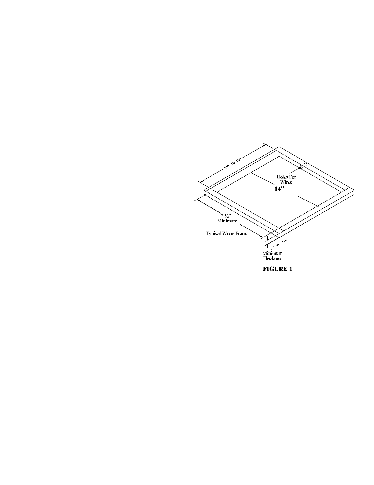
Is the roof of the vehicle capable of supporting both the roof
top unit and ceiling assembly without additional support
structures? Inspect the interior ceiling mounting area to
avoid interference with existing structural members such as:
bunks, curtains, tracks or room dividers. The depth of the
ceiling assembly shroud is 3". Be sure to check clearance for
doors which must be swung open (refrigerator, closets,
cabinets).
Most of the time, roof mount heat pumps are installed at
existing roof vent locations. If there are no roof vents
(existing mounting hole), the following placement locations
are recommended.
Motor Homes - a single unit or the forward of two units
should be mounted within 9 feet of the drivers compartment.
Travel Trailers or Mini-Homes - a location should be selected
that is near the door slightly forward of the vehicle center
length.
Vans - location should be in the center of the roof (side to
side - front to back).
Truck with Camper - location should be between 4 or 5 feet
from the rear of the camper to achieve maximum cooling
effect.
IV. INSTALLING THE ROOF TOP UNIT
DANGER
SHOCK HAZARD
DISCONNECT ALL POWER TO THE VEHICLE
BEFORE PERFORMING ANY CUTTING TO THE
VEHICLE. CONTACT WITH HIGH VOLTAGE CAN
RESULT IN EQUIPMENT DAMAGE, PERSONAL
INJURY OR DEATH.
IMPORTANT
TO PREVENT DAMAGE TO THE WIRING AND
BATTERY, DISCONNECT THE BATTERY CABLE
FROM THE POSITIVE BATTERY TERMINAL
BEFORE PERFORMING ANY CUTTING TO THE

4
VEHICLE.
Once the location for your heat pump has been determined
(See Section III), a reinforced and framed roof hole opening
must be provided (may use existing vent hole). Before cutting
into the vehicle roof, verify that the cutting action will clear
all structural members and crossbeams. Additionally, the
location of any inner roof plumbing and electrical supplies
must be considered.
A. If a roof vent is already present in the desired
mounting location for the heat pump, the following
steps must be taken:
1. Remove all screws which secure the roof
vent to the vehicle. Remove the vent and
any additional trim materials. Carefully
remove all chalking from around the roof
vent opening to obtain clean exterior roof
surface.
2. It may be necessary to seal some of the old
roof vent mounting screw holes which may
fall outside of the heat pump basepan
gasket.
3. Examine the roof opening. If the opening is
smaller than 14" x 14", the opening must be
enlarged (See Figure 1).
B. If a roof vent opening is not used, a new opening
(See Figure 1) will have to be cut into the vehicle
roof. A matching opening will also have to be cut
into the interior vehicle ceiling. Be careful when
cutting the ceiling opening. If the ceiling opening
is carpeted, snagging could occur. After the opening
in the roof and interior ceiling are the correct size,
a framed support structure must be provided between
exterior roof top and interior ceiling. The reinforced
framed structure must provide the following
guidelines:
1. Capable of supporting both the weight of
the roof top heat pump and the interior
ceiling assembly.
2. Capable of holding or supporting the roof
outer surface and interior ceiling apart, so
that when the roof top heat pump and
ceiling assembly are bolted together, no
collapsing occurs.
The frame must provide an opening to allow passage
for the power supply wiring. Route the supply
wiring through the frame at the same time the
support frame is being installed.
C. This heat pump is to be installed in accordance
with NFPA Standard 501C.
D. The roof top heat pump must be mounted as
near level from front to rear and side to side as is
possible when the vehicle is parked on a level plane.
Figures 2 and 3 show maximum allowable degree
deviations (mounting degrees from total surface flat
plane).

5
If the roof of the vehicle is sloped (not level) such
that the roof top heat pump cannot be mounted
within the maximum allowable degree deviations, an
exterior leveling shim will need to be added to make
the roof top heat pump level. A typical leveling
shim is shown in Figure 4.
E. After the mounting hole area is properly prepared,
remove the carton and shipping pads from the roof
top heat pump. Carefully lift the unit on top of
the vehicle. Do not use the outer plastic shroud
for lifting. Place the roof top heat pump over
the prepared mounting hole. The pointed end
(nose) of the shroud must face towards the front of
the vehicle. Pull the electrical conduit down from
the roof heat pump through the mounting opening
and let hang.

6
V. SECURING THE HEAT PUMP TO THE ROOF
A mounting frame is supplied with the ceiling assembly.
Follow the steps below to secure the heat pump to the roof.
Refer to Figure 5.
A. Locate the heat pump mount gasket over the 14" to
15" square opening in the roof.
B. Install the ceiling assembly mount
frame using the
four bolts found with the ceiling
assembly.
C. Proper tension has been achieved for each bolt when
any portion of each gasket indicating tab has been
pulled down even with the roof. See Figure 5. The
upper unit has now been properly installed with
optimum gasket compression.
FIGURE 5

7
The Following Two Sections Pertain Only To 8000 Series Ceiling Assemblies
VI. ELECTRICAL WIRING
ROUTING 115 VAC WIRING
Following RV Products high voltage wiring specifications
and all local and national electrical codes, route the roof top
unit 115 VAC supply wiring from its power source to the
wirebox.
High Voltage Wiring Specifications
1. U.L. requires copper conductors only with minimum
#12 AWG.
2. To prevent voltage drops greater than 10% during
starting loads, adhere to the following guideline:
For lengths greater than 50', use #10 AWG.
Circuit Protection - Refer to upper unit nameplate.
DANGER - SHOCK HAZARD
MAKE SURE THAT ALL POWER SUPPLY TO THE
UNIT IS DISCONNECTED BEFORE PERFORMING
ANY WORK ON THE UNIT TO AVOID THE
POSSIBILITY OF SHOCK INJURY OR DAMAGE TO
THE EQUIPMENT.
DANGER
WHEN USING NON-METALLIC
SHEATH CABLES (ROMEX, ETC.),
STRIP SHEATH BACK TO EXPOSE
4-6 INCHES OF THE SUPPLY LEADS.
STRIP THE INDIVIDUAL WIRE LEAD
ENDS FOR WIRE CONNECTION
(ABOUT 3/4" BARE WIRE). INSERT
THE SUPPLY WIRES INTO THE
ELECTRICAL CONNECTOR CLAMP.
SHEATH MUST PROTRUDE PAST
THE CLAMP BUSHING INSIDE THE
BOX AS ILLUSTRATED. MAKE SURE
SHEATH CABLE IS CENTERED IN
CLAMP BEFORE TIGHTENING UP
ON IT. DO NOT OVERTIGHTEN!!
THIS COULD RESULT IN PINCHING
THROUGH THE PLASTIC WIRE
INSULATION AND CAUSE SHORTING
OR “HOT” WIRES TO GROUND
(SHOCK HAZARD). THE CLAMP IS
INTENDED FOR STRAIN RELIEF OF
THE WIRES. SLIGHT PRESSURE IS
USUALLY SUFFICIENT TO
ACCOMPLISH THIS.
IF OTHER THAN NON-METALLIC
CABLES ARE USED FOR SUPPLY
CONDUCTORS, APPROPRIATE
STRAIN RELIEF CONNECTORS OR
CLAMPS SHOULD BE USED.
IN NO CASE SHOULD CLAMPING
OR PINCHING ACTION BE APPLIED
TO THE INDIVIDUAL SUPPLY LEADS
(NEUTRAL AND “HOT” WIRES).
DANGER
SHOCK HAZARD
TO PREVENT THE POSSIBILITY OF
SHOCK INJURY, THE WHITE WIRE
MUST BE CONNECTED TO NEUTRAL
IN THE SERVICE BOX ENTRANCE
AND THE MECHANICAL GROUND
MUST BE CONNECTED TO A
GROUNDING LUG EITHER IN THE
SERVICE BOX OR THE MOTOR
GENERATOR COMPARTMENT.

8
VII. INSTALLING THE CEILING ASSEMBLY (8000 SERIES)
NOTE
The optional Elect-A-Heat is intended to take the chill out of
the indoor air when the air is a few degrees too cool for
comfort. The Elect-A-Heat is an effective “chill chaser”. It
is not a substitute for a furnace.
Make sure that you have properly matched the roof top heat
pump and interior ceiling assembly. The following step by
step instructions must be performed in the following sequence
to insure proper installation.
A. Carefully uncarton the ceiling assembly. Controls
are factory installed in the ceiling assembly (except
ceiling assemblies for applications with remote
control box/thermostat).
B. Remove the shroud from the ceiling assembly plate.
C. THIS ENTIRE STEP “C” IS NOT REQUIRED ON
“COOLING ONLY” CEILING ASSEMBLIES. On
ceiling assemblies equipped with the Elect-A-
Heat heater package (heat/cool ceiling assemblies),
detach the bottom heating element support plate by
removing the screws located around the outer edge.
The electrical connection plug will need to be
disconnected before the heat element support plate
can be removed.
D. Before the ceiling assembly can be mounted to the
mount frame, the duct collar must be fastened to the
basepan of the heat pump with three (3) screws
(See Figure 6).
E. Secure the ceiling assembly plate to the mounting
frame with the screws provided.
F. Pull fabric duct material through ceiling assembly
discharge duct opening. Slit the 4 corners of fabric
duct which extends below duct opening (See
Figure 6).
DANGER
- FIRE HAZARD -
DO NOT USE FABRIC DUCT TAPE ON OR AROUND
FABRIC DISCHARGE AIR DUCT COLLAR.
ALUMINUM TAPE MAY BE USED IF NEEDED.

9
G. Place metal flange in discharge duct opening,
trapping fabric between it and the ceiling assembly
(See Figure 6).
H. Pull fabric tight. This will minimize material
bunching inside the discharge duct collar.
I. Fasten the metal flange to the ceiling assembly with
four (4) screws. To avoid air noise and
restrictions, trim any excess fabric that may
extend beyond edge of metal flange.
J. Route the power supply wire to the back of the
selector switch control box. Do not attach at this
time.
K. Take the roof top heat pump electrical conduit and
plug it into the back of the thermostat control box.
Make sure that the “ridged” side of the plug is
aligned and matched with the “ridged” side of
thermostat control box connection. DO NOT USE
EXCESSIVE FORCE and make sure the lock-in tabs
are snapped in place (See Figure 7).
L. Remove the selector switch control box cover (one
screw). Take the supply wire and slide it into the
back of the selector switch control box through the
strain relief that is provided.
M. Connect the power line to the black and white pigtail
wires found in the control box using two wire nuts.
IMPORTANT - Connect black wire to black wire
and white wire to white wire. Install the ground
wire (green to bare copper) to the green headed
screw in the selector switch control box. Using a
U.L. approved electricians tape, secure the wire nuts
to the wires in a workmanlike manner (See Figure
8).
N. Tighten the strain relief clamp to secure the supply
wire. DO NOT OVERTIGHTEN (See Figure 9).
Reinstall the selector switch control box cover.
Some ceiling assemblies may be equipped with a
plastic strain relief.

10
FIGURE 6

11
FIGURE 7
FIG
URE
8
FIGURE 9
VIII. COMPLETING THE INSTALLATION (8000 SERIES)
To complete the installation and system checkout
requirements, the following steps must be performed.
A. Check the thermostat probe position. Make sure the
thermostat probe is routed through the holding guide
and is not touching any metal surface.
B. THIS ENTIRE STEP “B” IS NOT REQUIRED ON
“COOLING ONLY” CEILING ASSEMBLIES.
Reinstall the Elect-A-Heat assembly by first;
connecting the heat plug from the selector switch
control box to the heater receptacle in the Elect-A-
Heat heater package, and secondly; secure the
Elect-A-Heat package to the ceiling assembly with
the screws previously removed.
C. Make sure the non-allergenic filters are properly
positioned in the ceiling shroud.
D. Reinstall the ceiling shroud (secure with two screws
provided by RV Products). Put the control knobs
(found in single parts package) on the selector
switch and thermostat controls.
E. Turn selector switch to OFF position.
F. Turn ON the power supply to the roof top heat
pump.
G. System Checkout - RV Products manufactures a
wide
range of roof top heat pumps which incorporate
different product operation features. To properly
evaluate the performance of a newly installed heat
pump, it is necessary to review the specific unit
operation characteristics (features) described in
product operation and maintenance instructions
(Customer Envelope Package).
The Following Two Sections Pertain Only To 9000 Series Ceiling Assemblies
IX. INSTALLING THE CEILING ASSEMBLY (9000 SERIES)
NOTE
The optional Elect-A-Heat is intended to take the chill out of
the indoor air when the air is a few degrees too cool for
comfort. The Elect-A-Heat is an effective “chill chaser”. It
is not a substitute for a furnace.
Make sure that you have properly matched the roof top heat
pump and interior ceiling assembly. The following step by
step instructions must be performed in the following sequence
to insure proper installation.
A. Carefully uncarton the ceiling assembly. Controls
are factory installed in the ceiling assembly (except
ceiling assemblies for applications with remote
control box/thermostat).
B. Remove the grille and filters from the ceiling
assembly.

12
C. If equipped with Elect-A-Heat option, remove the
heater assembly from the ceiling assembly chute.
Position the heater assembly in the heat pump return
air opening as shown in Figure 10. The heater
bracket must be installed over the metal basepan
extrusion and positioned between the basepan and
the plastic drain pan (See Figure 11). Tighten set
screw to secure the assembly so as to prevent
movement.
D. Fasten the duct collar to the basepan of the heat
pump with three (3) screws (See Figure 14).
E. Plug the roof top heat pump electrical conduit into
the 9 position receptacle located in the thermostat
side of the ceiling assembly. If installing an Elect-
A-Heat equipped ceiling assembly, plug the heater
cord into the 2 position receptacle (See Figure 12).
F.
Install the provided cable clamp in the 7/8" dia. hole on the
back of the metal field wiring box. Insert the supply wiring
through the cable clamp and into the field wiring box so that
4 - 6" of supply conductor is inside the box. Secure the cable
clamp over the supply wire sheath so that no movement is
possible (See Figure 13).
G. Connect the supply power conductors to the black
and white pigtail wires and the supply ground wire
to the green pigtail wire found in the field wiring
box using the 3 provided wire nuts. IMPORTANT -
Connect the black supply to the black pigtail and the
white supply to the white pigtail. Using a U.L.
approved electrical tape, secure the wire nuts to
wires in a workmanlike manner (See Figure 13).
H. Place the metal control box shield
over the thermostat, switch and
field wiring boxes.
Make certain
that all
wires are
pushe d into
the contr
ol boxes
or laying
in the
wir eway
betwee n the
thermostat and switch boxes
and will not be pinched by the control
box shield. Control box shield is properly
installed when the two holes in the shield are aligned with the
two screw holes in the ceiling assembly chute (See Figure 12).
I. Raise the ceiling assembly and secure to the
mounting frame with 4 provided shoulder
screw/spring assemblies. The front two screws
should pass through the clearance holes in the metal
control box shield (See Figure 14).
J. Pull the fabric duct material through ceiling
assembly discharge opening. Peel the release liner
from the adhesive strip around the discharge
opening. Press the fabric duct material firmly in
place around opening. Cut off excess fabric on
inside of ceiling assembly chute with a box knife
taking care not to tear the fabric beyond the adhesive
strip.

13
FIGURE 10
FIGURE 11
FIGURE 12
FIGURE 13

14
FIGURE 14
X. COMPLETING THE INSTALLATION (9000 SERIES)
A. Make sure the non-allergenic filters are properly
positioned in the ceiling grille.
B. Install the ceiling grille by positioning on the bottom
of the shroud and engaging the two 1/4 turn
fasteners.
C. Turn the selector switch to OFF position.
D. Turn ON the power supply to the roof top heat
pump.
E. System Checkout - RV Products manufactures a
wide range of roof top heat pumps which incorporate
different product operation features. To properly
evaluate the performance of a newly installed heat
pump, it is necessary to review the specific unit
operation characteristics (features) described in
product operation and maintenance instructions
(Customer Envelope Package).

15
TABLE DES MATIÈRES
I. Renseignements généraux . . . . . . . . . . . . . . . . . . . . . . . . . . . . . . . . . . . . . . . . . . . . . . . . . . . . . . . . . . . 13
II. Configuration de la pompe thermique . . . . . . . . . . . . . . . . . . . . . . . . . . . . . . . . . . . . . . . . . . . . . . . . . 14
III. Choix d’un emplacement pour l’installation . . . . . . . . . . . . . . . . . . . . . . . . . . . . . . . . . . . . . . . . . . . . 14
IV. Installation de l’appareil sur le toit . . . . . . . . . . . . . . . . . . . . . . . . . . . . . . . . . . . . . . . . . . . . . . . . . . . 15
V. Fixer la pompe thermique au toit . . . . . . . . . . . . . . . . . . . . . . . . . . . . . . . . . . . . . . . . . . . . . . . . . . . . . 16
VI. Câblage électrique . . . . . . . . . . . . . . . . . . . . . . . . . . . . . . . . . . . . . . . . . . . . . . . . . . . . . . . . . . . . . . . . . 16
VII. Installation du montage de plafond (série 8000) . . . . . . . . . . . . . . . . . . . . . . . . . . . . . . . . . . . . . . . . . 17
VIII. Fin de l’installation (série 8000) . . . . . . . . . . . . . . . . . . . . . . . . . . . . . . . . . . . . . . . . . . . . . . . . . . . . . . 18
IX. Installation du montage de plafond (série 9000) . . . . . . . . . . . . . .. . . . . . . . . . . . . . . . . . . . . . . . . . . 18
X. Fin de l’installation (série 9000) . . . . . . . . . . . . . . . . . . . . . . . . . . . . . . . . . . . . . . . . . . . . . . . . . . . . . . 19
Ces instructions sont un guide général d’installation des pompes thermiques de toit de la série 8000 de RV Products. Pour des
détails précis sur les pompes thermiques, vous devrez vous reporter à la pochette de documentation fournie avec chaque pompe
thermique.
NOTICE IMPORTANTE
Ces instructions doivent être utilisées par des personnes
qualifiées spécialement formées et connaissant les procédures
d’installation de ce type d’équipement et des composants du
système connexe.
Certains États exigent que le personnel responsable de
l’installation et de l’entretien ou de la réparation soit autorisé.
LES PERSONNES NON QUALIFIÉES NE DOIVENT PAS
INSTALLER NI FAIRE L’ENTRETIEN OU LA
RÉPARATION DE CET ÉQUIPEMENT.
REMARQUE
Le terme « doit » ou « doivent » indique une
exigence essentielle pour une performance
satisfaisante et sans danger du produit.
Le terme « devrait » ou « devraient » indique
une recommandation ou un conseil qui n’est
pas essentiel ni requis, mais qui pourrait
être utile.
AVERTISSEMENT - DANGER DE CHOC
ÉLECTRIQUE
Pour éviter toute possibilité de blessures graves ou de
dommages à l’équipement suite à un choc électrique,
assurez-vous de toujours mettre l’appareil hors tension.
SUIVEZ ATTENTIVEMENT TOUTES LES
INSTRUCTIONS ET TOUS LES AVERTISSEMENTS
DANS CE LIVRET POUR ÉVITER D’ENDOMMAGER
L’ÉQUIPEMENT, DE PROVOQUER DES BLESSURES
OU DES INCENDIES.
AVERTISSEMENT
Une mauvaise installation peut endommager l’équipement,
créer des dangers et annuler la garantie.
Le fait d’utiliser des composants non testés conformément
à ces appareils annule la garantie, peut rendre
l’équipement non conforme aux codes d’état, créer un
danger et détruire l’équipement.
I. RENSEIGNEMENTS GÉNÉRAUX
OEM (Fabricant d’équipement d’origine) - Veuillez vous
assurer que la pochette de documentation accompagne la
pompe thermique.
INSTALLATEUR ET/OU CONCESSIONNAIRE - Veuillez
vous assurer que le client reçoive la pochette de
documentation. Il devrait aussi avoir la possibilité d’acheter
le contrat de trois (3) ans de pièces de rechange de RV
Products.
Pour plus d’information au sujet du contrat, veuillez consulter
le contrat type qui se trouve dans le livret du mode d’emploi
et d’entretien (pochette de documentation). Utilisez la carte
fixée à la pochette de documentation pour faire la demande de
contrat de pièces prolongé.

16
QUESTIONS SUR LA POMPE THERMIQUE - Pour toutes
questions au sujet de l’installation du produit adressées à
votre représentant RV Products ou à RV Products, veuillez
indiquer les numéros de modèle et de série de la pompe
thermique de toit. Toutes ces pompes thermiques sont
identifiées par des numéros de série et de modèle qui se
trouvent à deux endroits: (1) étiquette signalétique que vous
pouvez voir dans les persiennes de carénage du côté
compresseur de la pompe thermique de toit. Vous pouvez la
voir sans retirer le carénage extérieur de plastique, (2)
l’étiquette au numéro de série/modèle (de couleur argent) se
trouve au bas du plateau de la pompe thermique de toit. Si la
pompe thermique est installée, vous pouvez voir l’étiquette en
abaissant le carénage du plafond.
II. CONFIGURATION DE LA POMPE THERMIQUE
Les capacités nominales des pompes thermiques devraient
être établies selon leur capacité de refroidir. La mesure
thermique utilisée pour détecter un gain ou une perte de
chaleur est la British Thermal Unit (BTU). Un (1) BTU est
la quantité de chaleur requise pour augmenter la température
d’une livre d’eau d’un degré Fahrenheit. Une pompe
thermique d’une capacité nominale de 13 500 BTUH peut
retirer 13 500 BTU de chaleur en une heure.
La capacité de refroidissement d’un véhicule ou de maintien
de la température choisie par le client grâce à la pompe
thermique dépend du gain de chaleur du véhicule. La taille
physique, la superficie des fenêtres, la qualité et la quantité
d’isolation, l’exposition au soleil, le nombre de personnes
utilisant le véhicule ainsi que la température extérieure
peuvent augmenter le gain de chaleur à tel point que la
capacité de la pompe thermique est dépassée.
En règle générale, l’air fourni (air de décharge) par la pompe
thermique sera de 15 à 20 degrés Fahrenheit ( 9 à 13 degrés
Celsius) plus frais que l’air qui entre (air recyclé) par les
grilles à air inférieures de l’assemblage du plafond.
Par exemple, si l’air entre dans la pompe thermique (l’air
recyclé) est de 80 degrés Fahrenheit (27 degrés Celsius) l’air
d’alimentation (air de décharge) dans le véhicule sera de 60 à
65 degrés Fahrenheit (15 à 18 degrés Celsius). Aussi
longtemps que cette différence de température (15 à 20
degrés) est maintenue à la pompe thermique, la pompe
thermique fonctionne correctement.
Attention à nouveau aux gains variables de chaleur du
véhicule. Lorsque les températures extérieures sont extrêmes,
le gain de chaleur du véhicule peut être réduit en:
‚stationnant la voiture à l’ombre
‚gardant les fenêtres et les portes fermées
‚évitant d’utiliser des appareils produisant de la
chaleur
‚utilisant des toiles pour les fenêtres (stores et/ou
rideaux)
Pour une solution plus permanente des situations de gain
prononcé de chaleur, il faudrait considérer de l’isolant de
véhicule, des auvents de fenêtres et/ou le teintage du verre des
fenêtres.
Une pompe thermique ne devrait pas être considérée comme
remplacement complet d’un appareil de chauffage. Lorsque
la température ambiante est sous le point de congélation, la
pompe thermique ne fonctionnera pas.
III. CHOIX D’UN EMPLACEMENT POUR L’INSTALLATION
Votre pompe thermique RV Products a été conçue pour être
utilisée avec les véhicules récréatifs.
Le toit du véhicule peut-il supporter à la fois l’appareil sur le
toit et le montage de plafond sans structures de support
additionnelles? Vérifiez le secteur du montage de plafond à
l’intérieur du véhicule pour éviter toute interférence avec les
structures actuelles telles que couchettes, rideaux, rails ou
séparateurs de pièces. La profondeur du carénage de plafond
est de 3 po (7,62 cm). Assurez-vous de vérifier le
dégagement des portes que vous devez ouvrir (réfrigérateur,
garde-robe, armoires).
La plupart du temps, les pompes thermiques de toit sont
installées sur les évents de toit actuels. S’il n’y a pas d’évents
de toit (ouvertures d’installation déjà en place), voici les
emplacements recommandés:

17
Autocaravanes - un seule appareil ou l’avant de deux
appareils devrait être monté jusqu’à 9 pieds (2,74 mètres) du
poste de conduite.
Caravanes classiques ou mini-maisons - il faudrait choisir un
emplacement près de la portière, un peu vers l’avant du
centre de la longueur du véhicule.
Fourgonnettes - l’emplacement devrait être au centre du toit
(d’un côté à l’autre - d’avant en arrière).
Camion avec caisse de camping - l’emplacement devrait être
entre 4 et 5 pieds (1,2 et 1,5 mètres) de l’arrière de la caisse
de camping pour obtenir un refroidissement maximum.
IV. INSTALLATION DE L’APPAREIL SUR LE TOIT
DANGER
CHOC ÉLECTRIQUE
COUPEZ TOUT COURANT AU VÉHICULE AVANT
TOUT TRAVAIL DE COUPE AU VÉHICULE. LE
CONTACT AVEC UNE HAUTE TENSION PEUT
ENDOMMAGER L’ÉQUIPEMENT, PROVOQUER DES
BLESSURES ET MÊME LA MORT.
IMPORTANT
POUR ÉVITER TOUT DOMMAGE AU CÂBLAGE ET
À LA BATTERIE, DÉBRANCHEZ LE CÂBLE DE LA
BATTERIE DE LA BORNE POSITIVE DE LA
BATTERIE AVANT D’EFFECTUER TOUT TRAVAIL
DE COUPE AU VÉHICULE.
Après avoir déterminé l’emplacement de votre pompe
thermique (voir Section III), vous devez fournir une ouverture
sur le toit renforcée et encadrée (vous pouvez utiliser
l’ouverture d’évent déjà en place). Avant de couper le toit du
véhicule, vérifiez que l’appareil dégagera tous les éléments de
structure et les entretoises. Vous devez aussi considérer
l’emplacement de toute alimentation électrique et plomberie à
l’intérieur du toit.
A. S’il y a déjà un évent de toit à l’endroit choisi pour
l’installation de la pompe thermique, voici les étapes
à suivre:
1. Retirez toutes les vis qui fixent l’évent au
toit du véhicule. Retirez ensuite l’évent et
toute garniture supplémentaire. Retirez
avec soin tout calfeutrage autour de
l’ouverture de l’évent pour avoir une
surface extérieure propre.
2. Vous devrez peut-être sceller certains des
trous de vis d’installation de l’ancien évent
sur le toit qui pourraient être à l’extérieur
du joint d’étanchéité du plateau de la pompe
thermique.
3. Examinez l’ouverture sur le toit. Si elle est
moins que 14 x 14 po (35,56 x 35,56 cm)
vous devez l’agrandir.
B. Si vous n’utilisez pas l’ouverture d’évent du toit, il
faudra couper une nouvelle ouverture dans le toit du
véhicule. Il faudra aussi couper une ouverture
semblable à l’intérieur du plafond du véhicule.
Attention en coupant l’ouverture du plafond. Si
cette ouverture est recouverte de tapis, il pourrait y
avoir

18
des accrocs. Après avoir une ouverture à la bonne
taille pour le toit et le plafond intérieur, prévoyez
une structure de support encadrée entre le dessus du
toit
extérieur et le plafond intérieur. La structure
encadrée renforcée doit respecter les directives
suivantes:
1. Elle doit pouvoir supporter à la fois le poids
de la pompe thermique de toit et le montage
de plafond intérieur.
2. Elle doit pouvoir retenir ou supporter la
surface extérieur du toit et le plafond
intérieur avec une séparation pour qu’après
avoir boulonné ensemble de la pompe
thermique et le montage de plafond, il n’y
ait aucun effondrement.
Le cadre doit fournir une ouverture pour
acheminer le câblage d’alimentation. Faites
passer le câblage d’alimentation par le
cadre lors de l’installation du cadre de
support.
C. La pompe thermique doit être installée
conformément à la norme 501C de la NFPA
(National Fire Protection Association).
D. La pompe thermique de toit doit être montée aussi à
niveau que possible, d’avant en arrière et d’un côté à
l’autre, lorsque le véhicule est stationné sur une
surface plane. [Les figures 2 et 3 illustrent les
déviations maximales permises (degrés de montage
de la surface plane de la surface totale).]
Si le toit du véhicule est en pente (pas à niveau) ne
permettant pas d’installer la pompe thermique de toit
avec les déviations maximales permises, vous devrez
ajouter une cale de mise à niveau pour que la pompe
thermique de toit soit à niveau. [La figure 4 présente
une cale de mise à niveau typique.]
E. Après avoir préparé correctement la région de
l’ouverture d’installation, retirez le carton et les
blocs d’expédition de la pompe thermique de toit.
Soulevez délicatement l’appareil sur le dessus du
véhicule. N’utilisez pas le carénage extérieur de
plastique pour soulever. Placez l’appareil sur
l’ouverture d’installation. L’extrémité pointue (nez)
du carénage doit faire face à l’avant du véhicule.
Tirez la conduite électrique vers le bas de la pompe
thermique de toit par l’ouverture d’installation et
laissez-la pendre.
V. FIXER LA POMPE THERMIQUE AU TOIT

19
Un cadre d’installation est fourni avec le montage de plafond.
Suivez les étapes ci-après pour fixer la pompe thermique au
toit.
A. Placez le joint plat de la pompe thermique sur
l’ouverture carrée de 14 ou 15 po (35,56 ou 38,1 cm)
du toit.
B. Installez le cadre d’installation du montage de
plafond en utilisant les quatre boulons qui se
trouvent avec le montage de plafond.
C. Les boulons sont bien installés lorsque chaque patte
indicatrice du joint se trouve à niveau avec le toit.
L’appareil supérieur est maintenant installé
correctement avec une compression de joint
optimale.
Les deux sections suivantes portent seulement sur les montages de plafond de la série 8000
VI. CÂBLAGE ÉLECTRIQUE
ACHEMINEMENT DU CÂBLAGE DE 115 V.C.A.
Acheminez le câblage d’alimentation de 115 V.c.a. de sa
source de courant à la boîte de connexion en respectant tous
les codes d’électricité nationaux et locaux ainsi que les
spécifications de câblage haute tension de RV Products.
Spécifications de câblage haute tension
1. U.L. exige d’utiliser seulement des conducteurs de
cuivre avec une grosseur minimum de 12 AWG.
2. Pour éviter les chutes de tension dépassant 10%
durant les charges de démarrage, respectez les
directives suivantes:
Pour les longueurs dépassant 50 pieds (15,24 m),
utilisez une grosseur de 10 AWG.
Protection de circuit - reportez-vous à la plaque
signalétique du produit supérieur.
DANGER - RISQUE DE CHOC
ASSUREZ-VOUS DE COUPER LE COURANT À
L’APPAREIL AVANT D’EFFECTUER TOUT
TRAVAIL SUR LA POMPE THERMIQUE POUR
ÉVITER LA POSSIBILITÉ DE CHOCS OU DE
DOMMAGES À L’ÉQUIPEMENT.
DANGER
EN UTILISANT DES CÂBLES À GAINE
NON-MÉTALLIQUE (ROMEX, ETC.),
DÉNUDEZ LA GAINE POUR EXPOSER
DE 4 À 6 POUCES (10,16 À 15,24 CM) DES
FILS D’ALIMENTATION. DÉNUDEZ LES
EXTRÉMITÉS DES FILS CONDUCTEURS
INDIVIDUELS POUR LE RACCORD DE
FILS (ENVIRON 3/4 PO [1,91 CM] DE FIL
NU). INSÉREZ LES FILS
D’ALIMENTATION DANS LA PINCE DU
CONNECTEUR ÉLECTRIQUE.
LA GAINE DOIT RESSORTIR DE LA
GARNITURE DE LA PINCE À
L’INTÉRIEUR DE LA BOÎTE TEL
QU’ILLUSTRÉ. ASSUREZ-VOUS QUE
LE CÂBLE GAINÉ EST CENTRÉ DANS
LA PINCE AVANT DE RESSERRER.
NE RESSERREZ PAS TROP!! CECI
POURRAIT MENER À DES PINCEMENTS
DANS L’ISOLANT PLASTIQUE DU FIL
ET PROVOQUER DES COURTS-
CIRCUITS OU DES FILS « CHARGÉS »
À LA MASSE. (RISQUE DE CHOC).
LA PINCE EST EN PLACE COMME
RÉDUCTEUR DE TENSION DES FILS.
POUR CE FAIRE, IL SUFFIT
NORMALEMENT D’UNE LÉGÈRE
PRESSION.
SI VOUS UTILISEZ DES CÂBLES
AUTRES QUE LES CÂBLES NON-
MÉTALLIQUES COMME
CONDUCTEURS D’ALIMENTATION,
VOUS DEVEZ UTILISER LES PINCES
OU CONNECTEURS DE RÉDUCTION
DE TENSION APPROPRIÉS.
VOUS NE DEVEZ, EN AUCUN CAS,
PINCER OU RESSERRER LES FILS
D’ALIMENTATION INDIVIDUELS
(FILS « CHARGÉS » ET NEUTRES).
DANGER
DANGER DE CHOC ÉLECTRIQUE
POUR ÉVITER LA POSSIBILITÉ DE
BLESSURES SUITE À DES CHOCS
ÉLECTRIQUES, LE FIL BLANC DOIT
ÊTRE CONNECTÉ AU NEUTRE À
L’ENTRÉE DU COFFRET DE

20
BRANCHEMENT ET LA MASSE
MÉCANIQUE CONNECTÉE À UNE
COSSE DE MASSE SOIT DANS LE
COFFRET DE BRANCHEMENT OU
DANS LE COMPARTIMENT DU
MOTEUR-GÉNÉRATEUR.
VII. INSTALLATION DU MONTAGE DE PLAFOND (SÉRIE 8000)
REMARQUE
L’Elect-A-Heat (optionnel) a pour but d’enlever l’air froid
intérieur lorsque l’air ambiant est un peu trop frais pour être
confortable. L’Elect-A-Heat est un moyen efficace de se
débarrasser des « frissons ». Il ne remplace pas l’appareil
de chauffage.
Assurez-vous d’avoir bien jumelé la pompe thermique de toit
et le montage de plafond intérieur. Voici les instructions,
étape par étape, à suivre pour assurer une bonne installation
en séquence de l’appareil.
A. Déballez avec soin le montage de plafond. Les
commandes sont installées en usine dans le montage
de plafond (sauf les montages pour les applications
avec thermostat ou télécommande).
B. Retirez le carénage de la plaque du montage de
plafond.
C. CETTE ÉTAPE « C » ENTIÈRE N’EST PAS
NÉCESSAIRE POUR LES MONTAGES DE
PLAFOND « RÉSERVÉS AU
REFROIDISSEMENT ». Pour les montages de
plafond doté d’un système Elect-A-Heat (montages
de plafond chaleur/refroidissement), retirez la plaque
de support de l’élément de chauffage inférieur en
enlevant les vis qui se trouvent autour du bord
extérieur. La prise de connexion électrique doit être
débranchée avant de retirer la plaque de support de
l’élément de chauffage.
D. Avant d’installer le montage de plafond au cadre
d’installation, il faut fixer le collet du conduit à la
pompe thermique avec trois (3) vis.
E. Fixez la plaque du montage de plafond au cadre
d’installation avec les vis fournies.
F. Faites passer le tissu de la gaine dans l’ouverture de
la gaine de décharge du montage de plafond. Faites
une entaille dans les 4 coins du tissu de la gaine qui
sort sous l’ouverture du conduit.
DANGER
- DANGER D’INCENDIE -
N’UTILISEZ PAS DE RUBAN DE GAINE EN TISSU
SUR OU AUTOUR DU COLLET DE CONDUIT D’AIR
DE LA DÉCHARGE. AU BESOIN, UTILISEZ DU
RUBAN D’ALUMINIUM.
G. Placez la bride métallique dans l’ouverture de la
gaine de décharge pour coincer le tissu entre la bride
et le montage de plafond.
H. Tirez le tissu bien serré. Ceci réduit l’entassement
du matérial à l’intérieur du collet de la gaine de
décharge.
I. Fixez la bride métallique dans le montage de plafond
avec quatre (4) vis. Pour éviter les restrictions et
les bruits d’air, taillez tout surplus de tissus qui
pourrait se prolonger au-delà du bord de la bride
métallique.
J. Acheminez le fil d’alimentation de courant à
l’arrière de la boîte de commande du sélecteur. Ne
le branchez pas maintenant.
K. Prenez le conduit électrique de la pompe thermique
de toit et raccordez-le à l’arrière de la boîte de
commande du thermostat. Assurez-vous que le côté
« nervuré » de la prise est alignée et jumelée au côté
« nervuré » de la connexion de la boîte de
commande du thermostat. N’UTILISEZ PAS TROP
DE FORCE et assurez-vous que les tenons
s’encliquettent en place.
L. Retirez le couvercle de la boîte de commande du
sélecteur (une vis). Prenez le fil d’alimentation et
glissez-le à l’arrière de la boîte de commande du
sélecteur par le réducteur de tension fourni.
M. Raccordez la ligne de transport d’énergie aux fils en
tire-bouchon blanc et noir qui se trouvent dans la
boîte de commande en utilisant les deux écrous de
câble. IMPORTANT - Raccordez le fil noir au fil
noir et le fil blanc au fil blanc. Installez le fil de
masse (vert au cuivre nu) à la vis à tête verte dans la
boîte de commande du sélecteur. Utilisez un ruban
d’électricité approuvé U.L. et fixez les écrous de
câble aux fils selon les règles du métier.
N. Resserrez la pince de réduction de tension pour fixer
le fil d’alimentation. NE RESSERREZ PAS TROP.
Replacez le couvercle de la boîte de commande du
sélecteur. Certains montages de plafond peuvent
avoir un réducteur de tension en plastique.
Other manuals for 8000 SERIES
2
Table of contents
Languages:
Other RVP Heat Pump manuals
Popular Heat Pump manuals by other brands

Arbonia
Arbonia DXA-ECM Installation and maintenance manual

York
York E4FD018-60 installation instructions

alphainnoTec
alphainnoTec LW 71A operating manual

Nibe
Nibe F2120-8 Installer manual

Carrier
Carrier 38YCA Series Installation and start-up instructions

Trane
Trane A4HP5 Installation and operation manual