Ryobi RY09800 User manual

OPERATOR’S MANUAL
MANUEL D’UTILISATION
MANUAL DEL OPERADOR
30cc BACKPACK BLOWER
30cc SOUFFLANTE DORSALE
30cc SOPLADORA DE
MOCHILA
RY09800
Ce soufflante dorsale a été conçu et fabriqué conformément à
nos strictes normes de fiabilité, simplicité d’emploi et sécurité
d’utilisation. Correctement entretenu, cet outil vous donnera des
années de fonctionnement robuste et sans problème.
AVERTISSEMENT : Pour réduire les risques de
blessures, l’utilisateur doit lire et veiller à bien comprendre le
manuel d’utilisation avant d’employer ce produit.
Merci de votre achat.
Su sopladora de mochila ha sido diseñado y fabricado de
conformidad con nuestras estrictas normas para brindar fiabilidad,
facilidad de uso y seguridad para el operador. Con el debido cuidado,
le brindará muchos años de sólido funcionamiento y sin problemas.
ADVERTENCIA: Para reducir el riesgo de lesiones,
el usuario debe leer y comprender el manual del operador antes
de usar este producto.
Le agradecemos su compra.
CONSERVER CE MANUEL POUR
FUTURE RÉFÉRENCE GUARDE ESTE MANUAL PARA
FUTURAS CONSULTAS
SAVE THIS MANUAL FOR FUTURE REFERENCE
Your blower has been engineered and manufactured to our high standard for dependability, ease of operation, and operator
safety. When properly cared for, it will give you years of rugged, trouble-free performance.
WARNING: To reduce the risk of injury, the user must read and understand the operator’s manual before using
this product.
Thank you for your purchase.

ii iii
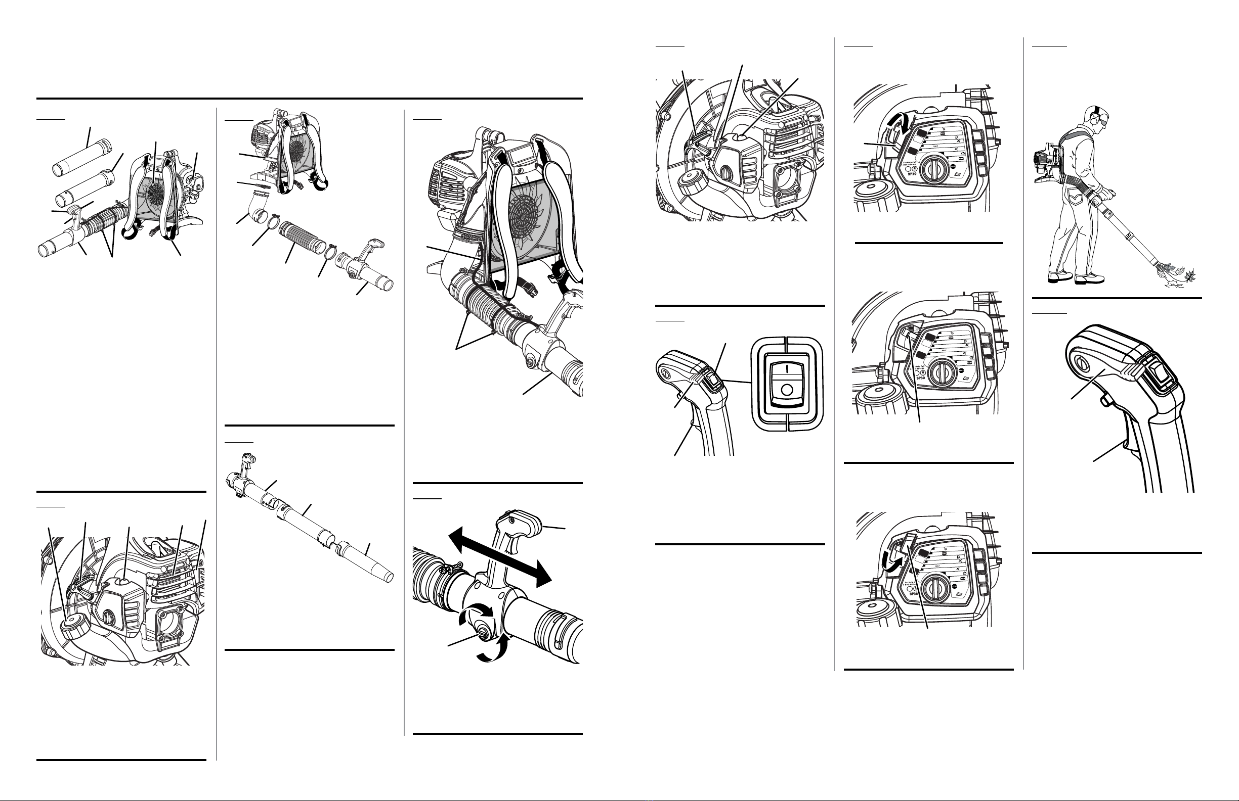
See this fold-out section for all the figures referenced in the operator’s manual.
Voir que cette section d’encart pour toutes les figures a adressé dans le manuel d’utilisation.
Vea esta sección de la página desplegable para todas las figuras mencionó en el manual del operador.
Fig. 1
A - Throttle control handle tube (tube de poignée
de commande d’accélérateur, tubo del
mango de control del acelerador)
B - Adjustable throttle control handle (poignée de
commande d’accélérateur, mango ajustable
de control del acelerador)
C - Throttle trigger (gâchette d’accélérateur,
gatillo del acelerador)
D - Choke lever (levier de volet de départ, palanca
del anegador)
E - Adjustable harness and waist straps (réglage
de hauteur du harnais, arnés ajustable y
correas de la cintura)
F - Cruise control (régulateur de vitesse, control
de crucero)
G - Mesh backing (doublure maillée, espaldar de
malla)
H
- Nozzle (buse, boquilla)
I
- Straight tube (tube droit, tubo recto)
J - Cable ties (serre-câbles, amarre de cables)
A
F
G
E
C
H
I
J
Fig. 6
A - Locking screw (vis de blocage, tornillo de
fijación)
B - Adjustable throttle control handle (poignée de
commande d’accélérateur, mango ajustable
de control del acelerador)
Fig. 5
C
b
A
A - Throttle control handle tube (tube de poignée
de commande d’accélérateur, tubo del mango
de control del acelerador)
B - Straight tube (tube droit, tubo recto)
C - Nozzle (buse, boquilla)
D
b
Fig. 4
Fig. 2
A - Primer bulb (poire d’amorçage, bomba de
cebado)
B - Starter grip and rope (poignée du lanceur et
corde, mango del arrancador y cuerda)
C - Fuel cap (bouchon du réservoir, tapa del
tanque de combustible)
D - Engine (moteur, motor)
E - Muffler (échappement, silenciador)
A
bD
C
A - Blower housing air outlet (sortie d’air
de boîtier du souffleur, salida de aire del
alojamiento de la sopladora)
B - Elbow (coude, codo)
C - Tube clamps (collier du tuyaus, abrazadera
del tubos)
D - Bellows (soufflet, tubo flexible)
E - Adjustable throttle control handle (poignée de
commande d’accélérateur, mango ajustable
de control del acelerador)
Fig. 3
Fig. 7 Fig. 9 Fig. 10
propEr opErAtInG posItIon
posItIon D’utIlIsAtIon CorrECtE
posICIón CorrECtA pArA El mAnEJo DE
lA HErrAmIEntA
A - Primer bulb (poire d’amorçage, bomba de
cebado)
B - Starter grip and rope (poignée du lanceur et
corde, mango del arrancador y cuerda)
C - Choke lever (levier de volet de départ, palanca
del anegador)
bA
Fig. 8
A
b
D
C
C
E
A - Throttle cable (câble d’accélérateur, cable
del acelerador)
B - Cable ties (serre-câbles, amarre de cables)
C - Throttle control handle tube (tube de poignée
de commande d’accélérateur, tubo del mango
de control del acelerador)
A
b
C
A
b
A - Throttle trigger (gâchette d’accélérateur,
gatillo del acelerador)
B - Stop switch (commutateur d’arrêt, interruptor
del apagado)
C - Cruise control (régulateur de vitesse, control
de crucero)
A
b
C
A
A
A
A - Cruise control (régulateur de vitesse, control
de crucero)
B -Throttle trigger (gâchette d’accélérateur,
gatillo del acelerador)
b
Fig. 11
C
C
PRIME
SET to
x10
LOCK throttle lever
WAIT 10 sec.
(4X
MAX)
PULL until engine starts
PULL
untilengine attempts to start
(6X MAX)
2
3
or until fuel appears
4
8
RUN
HALF
FULL
SET to
PRESS
switch
to stop
?
5
SET to
6
7
BP30
1
PRIME
SET to
x10
LOCK throttle lever
WAIT 10 sec.
(4X
MAX)
PULL until engine starts
PULL
untilengine attempts to start
(6X MAX)
2
3
or until fuel appears
4
8
RUN
HALF
FULL
SET to
PRESS
switch
to stop
?
5
SET to
6
7
BP30
1
A - Choke lever (levier de volet de départ, palanca
del anegador)
A - Choke lever (levier de volet de départ, palanca
del anegador)
run posItIon
posItIon DE mArCHE
posICIón DE FunCtIonAmIEnto
stArt posItIon
(posItIon DE DémArrAGE
posICIón DE ArrAnquE)
PRIME
SET to
x10
LOCK throttle lever
WAIT 10 sec.
(4X
MAX)
PULL until engine starts
PULL
untilengine attempts to start
(6X MAX)
2
3
or until fuel appears
4
8
RUN
HALF
FULL
SET to
PRESS
switch
to stop
?
5
SET to
6
7
BP30
1
A
HAlF CHokE posItIon
(posItIon DE étrAnGlEmEnt
posICIón DE AnEGACIón)
A - Choke lever (levier de volet de départ, palanca
del anegador)
E

2
Introduction ...................................................................................................................................................................... 2
Introduction / Introducción
General Safety Rules.....................................................................................................................................................3-4
Règles de sécurité générales / Reglas de seguridad generales 3-4 / 3-4
Specific Safety Rules........................................................................................................................................................ 4
Règles de sécurité particulières / Reglas de seguridad específicas 4 / 4
Symbols............................................................................................................................................................................ 5
Symboles / Símbolos 5 / 5
Features............................................................................................................................................................................ 6
Caractéristiques / Características 6 / 6
Assembly.......................................................................................................................................................................6-7
Assemblage / Armado 6-7 / 6-7
Operation.....................................................................................................................................................................8-10
Utilisation / Funcionamiento 8-10 / 8-10
Maintenance..............................................................................................................................................................10-11
Entretien / Mantenimiento 10-11 / 10-11
Troubleshooting.............................................................................................................................................................. 12
Dépannage / Solución de problemas 12 / 12
Warranty ....................................................................................................................................................................13-14
Garantie / Garantía 13-14 / 13-14
Parts Ordering and Service ...............................................................................................................................Back Page
Commande de pièces et réparation / Pedidos de piezas y servicio Page arrière / Pág. posterior
TABLE OF CONTENTS
TABLE DES MATIÈRES / ÍNDICE DE CONTENIDO
INTRODUCTION
INTRODUCTION / INTRODUCCIÓN
This product has many features for making its use more pleasant and enjoyable. Safety, performance, and dependability
have been given top priority in the design of this product making it easy to maintain and operate.
* * *
Ce produit offre de nombreuses fonctions destinées à rendre son utilisation plus plaisante et satisfaisante. Lors de la
conception de ce produit, l’accent a été mis sur la sécurité, les performances et la fiabilité, afin d’en faire un outil facile à
utiliser et à entretenir.
* * *
Este producto ofrece numerosas características para hacer más agradable y placentero su uso. En el diseño de este producto
se ha conferido prioridad a la seguridad, el desempeño y la fiabilidad, por lo cual se facilita su manejo y mantenimiento.

3 — English
GENERAL SAFETY RULES
WARNING:
Read and understand all instructions. Failure to follow
all instructions listed below may result in electric shock,
fire and/or carbon monoxide poisoning which will cause
death or serious personal injury.
Do not allow children or untrained individuals to use this
unit.
Never start orrunthe engineinside aclosedarea;breathing
exhaust fumes can kill.
Always wear eye protection with side shields marked to
comply with ANSI Z87.1, along with hearing protection.
Failure to do so could result in objects being thrown into
your eyes and other possible serious injuries.
Keep all bystanders, children, and pets at least 50 feet
away.
Wear heavy long pants, long sleeves, boots, and gloves.
Do not wear loose-fitting clothing, short pants, sandals,
jewelry of any kind, or go barefoot.
To reduce the risk of injury associated with objects being
drawn into rotating parts, do not wear loose clothing,
scarves, neck chains, and the like. Secure long hair so it
is above shoulder level to prevent entanglement in any
rotating parts.
Do not operate this unit when you are tired, ill, or under
the influence of alcohol, drugs, or medication.
Do not operate in poor lighting.
Keep all parts of your body away from any moving parts
and all hot surfaces of the unit.
Wear a face filter mask in dusty conditions to reduce the
risk of injury associated with the inhalation of dust.
Check the work area before each use. Remove all objects
such as rocks, broken glass, nails, wire, or string which
can be thrown or become entangled in the machine.
Keep firm footing and balance. Do not overreach.
Overreaching can result in loss of balance or exposure
to hot surfaces.
Never operate the unit without a spark arrestor screen;
this screen is located inside the muffler.
Productuserson United StatesForestService land,andin
somestates, must complywith fire preventionregulations.
This product is equipped with a spark arrestor; however,
otheruser requirementsmayapply. Checkwiththe federal,
state, or local authorities in your area.
Before storing, allow the engine to cool.
Use only manufacturer’s replacement parts and
accessories.Failuretodo so maycausepoor performance
or possible injury.
Maintain the unit per maintenance instructions in this
Operator’s Manual.
Inspect the unit before each use for loose fasteners, fuel
leaks, etc. Replace damaged parts.
Do not use on a ladder, rooftop, tree, or other unstable
support. Stable footing on a solid surface enables better
control of the blower in unexpected situations.
SERVICE
Before cleaning, repairing, or inspecting, shut off the
engine and make certain all moving parts have stopped.
Disconnect the spark plug wire, and keep the wire away
from the plug to prevent starting.
Service on the blower must be performed by qualified
repair personnel only. Service or maintenance performed
by unqualified personnel could result in injury to the user
or damage to the product.
Use only identical replacement parts when servicing the
product. Use of unauthorized parts may create a risk of
serious injury to the user, or damage to the product.

4 — English
SPECIFIC SAFETY RULES
To reduce the risk of hearing loss associated with sound
level(s), hearing protection is required.
To reduce the risk of injury associated with contacting
rotating parts, stop the engine before installing or
removing attachments. Do not operate without guard(s)
in place. Always disconnect the spark plug before
performing maintenance or accessing any movable parts.
Rotating impeller blades can cause severe injury. Do not
put hands or any other object into the blower housing air
outlet or blower tubes.
Do not point the blower nozzle in the direction of people
or pets.
Never run the unit without the blower tubes installed.
Never place objects inside the blower tubes.
Never use blower near fires, fireplaces, hot ashes, bar-
becue pits, etc., which may cause fire to spread.
Never place blower on any surface, except a hard, clean
surface when engine is running. Gravel, sand, and other
debris can be picked up by the air inlet and thrown at the
operator or bystanders, causing possible serious injuries.
Never use for spreading chemicals, fertilizers, toxic sub-
stances, or any other hazardous chemical.
Always hold the throttle control handle in your right hand.
Refer to the OPERATION section later in this manual for
additional information.
REFUELING
Fuel is highly flammable. Take precautions when using
to reduce the chance of serious personal injury.
Empty fuel tank and restrain the unit from moving before
transporting in a vehicle.
To reduce the risk of fire and burn injury, handle fuel with
care. It is highly flammable.
Do not smoke while handling fuel.
Mix and store fuel in a container approved for gasoline.
Mix fuel outdoors where there are no sparks or flames.
Select bare ground, stop engine, and allow to cool before
refueling.
Loosen fuel cap slowly to release pressure and to keep
fuel from escaping around the cap.
Tighten the fuel cap securely after refueling.
Wipe spilled fuel from the unit. Move 30 feet away from
refueling site before starting engine.
Never attempt to burn off spilled fuel under any circum-
stances.
Store fuel in a cool, well-ventilated area, safely away from
spark and/or flame-producing equipment.
Store fuel in containers specifically designed for this
purpose.
Only refuel outdoors and do not smoke while refueling.
Add fuel before starting the engine. Never remove the cap
of the fuel tank or add fuel while the engine is running or
when the engine is hot.
If fuel is spilled, do not attempt to start the engine but
move the machine away from the area of spillage and
avoid creating any source of ignition until fuel vapors
have dissipated.
Replace all fuel tank and container caps securely.
When draining the fuel tank, use an approved fuel storage
container while in a well-ventilated area.
Save these instructions. Refer to them frequently and use
them to instruct others who may use this product. If you
loan someone this product, loan them these instructions
also.

5 — English
SYMBOLS
The following signal words and meanings are intended to explain the levels of risk associated with this product.
SYMBOL SIGNAL MEANING
DANGER: Indicates an imminently hazardous situation, which, if not avoided, will result
in death or serious injury.
WARNING: Indicates a potentially hazardous situation, which, if not avoided, could result
in death or serious injury.
CAUTION: Indicates a potentially hazardous situation, which, if not avoided, may result in
minor or moderate injury.
CAUTION: (Without Safety Alert Symbol) Indicates a situation that may result in property
damage.
Some of the following symbols may be used on this product. Please study them and learn their meaning. Proper
interpretation of these symbols will allow you to operate the product better and safer.
SYMBOL NAME EXPLANATION
Safety Alert Symbol Indicates a potential personal injury hazard
Read Operator’s Manual To reduce the risk of injury, user must read and understand operator’s
manual before using this product
Eye and Hearing
Protection
Always wear eye protection with side shields marked to comply with
ANSI Z87.1 along with hearing protection.
Impeller Blades Rotating impeller blades can cause severe injury.
Blower Tubes Do not operate without tubes in place.
Long Hair Risk of long hair being drawn into air inlet
Loose Clothing Risk of loose clothing being drawn into air intake
Keep Bystanders Away Keep all bystanders at least 50 ft. away.
Ricochet Thrown objects can ricochet and result in personal injury or property
damage.
Gasoline and Oil
Use unleaded gasoline intended for motor vehicle use with an octane
rating of 87 [(R + M) / 2] or higher. This product is powered by a 2-cycle
engine and requires pre-mixing gasoline and 2-cycle oil.

6 — English
KNOW YOUR BLOWER
See Figures 1 - 3.
The safe use of this product requires an understanding of
the information on the product and in this operator’s manual
as well as a knowledge of the project you are attempting.
Before use of this product, familiarize yourself with all op-
erating features and safety rules.
ADJUSTABLE HARNESS AND WAIST STRAPS
The blower comes with fully adjustable harness and waist
straps to ensure user comfort and ease of operation.
ADJUSTABLE THROTTLE CONTROL HANDLE
Easily adjust throttle control handle by loosening handle
knob to position handle in desired location.
CRUISE CONTROL
The cruise control feature allows the user to operate the
blower without holding the throttle.
ENGINE
The blower has a powerful 30cc engine with sufficient power
to handle tough jobs.
MESH BACKING
The blower comes equipped with a mesh backing which
aids in user comfort.
THROTTLE TRIGGER
The blower can be operated at any speed between idle and
full throttle.
UNPACKING
This product requires assembly.
Carefully remove the product and any accessories from
the box. Make sure that all items listed in the packing list
are included.
WARNING:
Do not use this product if any parts on the Packing List
are already assembled to your product when you unpack
it. Parts on this list are not assembled to the product by
the manufacturer and require customer installation. Use
of a product that may have been improperly assembled
could result in serious personal injury.
Inspect the product carefully to make sure no breakage
or damage occurred during shipping.
Donot discardthe packing materialuntilyou have carefully
inspected and satisfactorily operated the product.
If any parts are damaged or missing, please call
1-800-860-4050 for assistance.
FEATURES
ASSEMBLY
PACKING LIST
Backpack Blower
Bellows
Throttle Control Handle Tube
Elbow
Straight Tube
Nozzle
Cable Ties (2)
Tube Clamp (3)
2-Cycle Engine Oil
Operator’s Manual
NOTE: Read and remove all hang tags and store with your
operator’s manual.
PRODUCT SPECIFICATIONS
Engine Displacement....................................................30cc
Weight .......................................................................15 lbs.
Air Velocity:
MPH........................................................................... 145
CFM ........................................................................... 370

7 — English
ASSEMBLY
WARNING:
If any parts are damaged or missing do not operate
this product until the parts are replaced. Use of this
product with damaged or missing parts could result in
serious personal injury.
WARNING:
Do not attempt to modify this product or create acces-
sories not recommended for use with this product. Any
such alteration or modification is misuse and could result
in a hazardous condition leading to possible serious
personal injury.
WARNING:
To prevent accidental starting that could cause serious
personal injury, always disconnect the engine spark plug
wire from the spark plug when assembling parts.
WARNING:
Disconnect the spark plug wire before assembling parts.
Failure to do so could result in possible serious personal
injury.
ASSEMBLING THE BLOWER TUBES
See Figures 3 - 5.
Place a tube clamp on blower housing air outlet past
the raised tabs. Assemble the elbow tube onto blower
housing air outlet by aligning raised tabs on blower with
slots on elbow. Tighten tube clamp onto elbow.
Attach bellows onto elbow tube by placing a tube clamp
on one end of the bellows then press bellows onto elbow
tube. Tighten tube clamp.
Place a tube clamp on other end of bellows. Press bellows
onto throttle control handle tube. Tighten tube clamp.
NOTE: The position of the throttle control handle may be
adjusted for comfort after the blower is strapped onto the
operator’s back.
Join the straight tube and nozzle together by aligning
raised locking tabs on straight tube with the raised locking
slots on nozzle and twist to secure.
Assemble the connected lower tubes to the throttle
control handle tube by aligning raised locking tabs on the
throttle control handle tube with the raised locking slots
on connected lower tubes by twisting to secure.
NOTE: Check all locking connections after initial run to
ensure they are tightly secured.
Hold the throttle cable against the bellows and install the
cable ties. Cable ties should be tight enough to retain the
throttle cable to the bellows but still allow for movement.
CAUTION:
Make all adjustments to the harness straps before start-
ing the blower to avoid the possibility of injury.
ADJUSTING HARNESS AND WAIST STRAPS
Straps should be adjusted to a comfortable position before
starting the blower.
To adjust harness strap assembly:
Blower should be in operating position before adjusting
the harness straps. Slip arm through harness strap and
onto shoulder, then repeat for the other shoulder.
There are three possible height adjustment positions that
can be used to easily adjust harness.
Slip top buckle of harness from adjustment slot and
position to desired height location.
Tighten (pull down on strap) or loosen (lift up on tab of
strap buckle) each harness strap as needed, until each
is adjusted to a comfortable operating position.
Chest strap should be tightened or loosened until adjusted
to a comfortable operating position.
To adjust waist strap assembly:
Waist strap should be tightened or loosened until adjusted
to a comfortable operating position.
ADJUSTING THROTTLE CONTROL HANDLE
See Figure 6.
Loosen locking screw by turning counterclockwise.
Move throttle control handle to desired position and
secure locking screw by turning clockwise.

8 — English
WARNING:
Do not allow familiarity with this product to make you
careless. Remember that a careless fraction of a second is
sufficient to inflict serious injury.
WARNING:
Always wear eye protection with side shields marked to
comply with ANSI Z87.1, along with hearing protection.
Failure to do so could result in objects being thrown into
your eyes and other possible serious injuries.
WARNING:
Do not use any attachments or accessories not recom-
mended by the manufacturer of this product. The use of
attachments or accessories not recommended can result
in serious personal injury.
APPLICATIONS
You may use this product for the purposes listed below:
Clear leaves and other debris from your lawn
Keeping decks and driveways free from grass clippings,
leaves, pine needles, and other debris
FUELING AND REFUELING THE BLOWER
WARNING:
Gasoline and its vapors are highly flammable and ex-
plosive. To prevent serious personal injury and property
damage, handle it with care. Keep away from ignition
sources and open flames, handle outdoors only, do not
smoke while mixing gasoline and lubricant together; and
wipe up spills immediately.
FUEL MIXTURE
This product is powered by a 2-cycle engine and requires
pre-mixing gasoline and 2-cycle lubricant. Pre-mix unleaded
gasoline and 2-cycle engine lubricant in a clean 1 gallon
container approved for gasoline.
Recommended fuel: This engine is certified to operate on
unleaded gasoline intended for automotive use.
Mix a high quality 2-cycle engine lubricant at 2.6 oz. per
gallon (US).
Do not use automotive lubricant or 2-cycle outboard
lubricant.
DO NOT mix quantities larger than usable in a 30 day period.
OPERATION
HIGH QUALITY 2-CYCLE ENGINE LUBRICANT
GASOLINE LUBRICANT
1 gallon (US) 2.6 oz.
1 liter 20 cc (20 ml)
FILLING TANK
Clean surface around fuel cap to prevent contam-
ination.
Loosen the fuel cap slowly by turning counterclockwise.
Rest the cap on a clean surface.
Carefully pour fuel into the tank. Avoid spillage.
Prior to replacing the fuel cap, clean and inspect the
gasket.
Immediately replace fuel cap and hand tighten by turning
it clockwise. Wipe up any fuel spillage.
Move at least 30 ft. away from refueling area before
starting the product.
WARNING:
Check for fuel leaks, which are a fire hazard. Failure
to do so could result in a fire that could cause serious
personal injury.
NOTE: It is normal for smoke to be emitted from a new
engine after first use.
WARNING:
Always shut off engine before fueling. Never add fuel to a
machine with a running or hot engine. Move at least 30 ft.
from refueling site before starting engine. Do not smoke
and stay away from open flames and sparks. Failure to
safely handle fuel could result in serious personal injury.
OXYGENATED FUELS
DO NOT USE E85 FUEL. IT WILL VOID YOUR WARRANTY.
NOTE: Fuel system damage or performance problems re-
sulting from the use of an oxygenated fuel containing more
than the percentages of oxygenates stated below are not
covered under warranty.
Ethanol. Gasoline containing up to 10% ethanol by volume
(commonly referred to as E10) or 15% ethanol by volume
(commonly referred to as E15) are acceptable. E85 is not.

9 — English
OPERATION
STARTING AND STOPPING
See Figures 7 - 9.
Blower should be on a flat, bare surface for starting.
Slowly press the primer bulb 10 times.
NOTE: After the 10th press, fuel should be visible in the
primer bulb. If it is not, continue to press the primer until
you see fuel in the bulb.
Set the choke lever to the FULL CHOKE position.
Lock cruise control.
Pull starter grip sharply until engine attempts to run. Do
not pull the starter grip more than four (4) times.
Set the choke lever to the HALF CHOKE position.
Pull the starter grip and rope until the engine runs. Do
not pull the starter grip more than six (6) times.
NOTE: If the engine does not start, return to the FULL
CHOKE position and repeat the steps that follow.
Allow the engine to run for 10 seconds, then set the choke
lever to the RUN position.
TO STOP THE ENGINE:
To stop the engine, depress the STOP switch to the stop
position “ O ”.
HOT RESTART OF THE ENGINE:
Set the choke lever to the RUN position.
Lock cruise control.
Pull the starter grip until the engine runs.
IF ASSISTANCE IS REQUIRED STARTING THIS
PRODUCT:
Do not return this product to the retail store where it was
purchased. Please call our Customer Service Department
for any issues you may have.
For Help Call: 1-800-860-4050.
WARNING:
Keep away from the muffler and all hot surfaces of the
blower. Failure to do so could result in possible serious
personal injury.
OPERATING THE BLOWER
See Figure 10.
Slip arm through harness strap and onto shoulder, then
repeat for the other shoulder. Adjust the straps to a
comfortableposition. Referto Adjusting Harness Straps
earlier in this manual. Remove unit for starting.
Start the blower. Refer to Starting and Stopping earlier
in this manual.
Put on the blower again. The unit should be operated on
the operator’s right side as shown.
To keep from scattering debris, blow around the outer
edges of a debris pile. Never blow directly into the center
of a pile.
Operate power equipment at reasonable hours only —
not early in the morning or late at night when people
might be disturbed. Comply with the times listed in local
ordinances.
To reduce sound levels, limit the number of pieces of
equipment used at any one time.
Operate blower at the lowest possible throttle speed to
do the job.
Check your equipment before operation, especially the
muffler, air intakes, and air filters.
Use rakes and brooms to loosen debris before blowing.
In dusty conditions, slightly dampen surfaces when water
is available.
Conserve water by using power blowers instead of hoses
for many lawn and garden applications, including areas
such as gutters, screens, patios, grills, porches, and
gardens.
Watch out for children, pets, open windows, or freshly
washed cars, and blow debris safely away.
Use the nozzle for larger volume, so the air stream can
work close to the ground.
After using blowers or other equipment, CLEAN UP!
Dispose of debris properly.
WARNING:
Do not place blower on top of or near loose debris. Debris
may be sucked into blower intake vent resulting in serious
personal injury and possible damage to the unit.
CRUISE CONTROL
See Figure 11.
The cruise control can be used to operate the blower without
holding the throttle trigger.
To engage the cruise control:
Pull cruise control lever back toward user, and stop at
the desired throttle setting.
To release the cruise control, push cruise control lever all
the way toward the front of unit.

10 — English
MAINTENANCE
WARNING:
When servicing, use only identical replacement parts.
Use of any other parts may create a hazard or cause
product damage.
WARNING:
Always wear eye protection with side shields marked to
comply with ANSI Z87.1, along with hearing protection.
Failure to do so could result in objects being thrown into
your eyes and other possible serious injuries.
WARNING:
Before inspecting, cleaning, troubleshooting, or servicing
the machine, shut off engine, wait for all moving parts to
stop, and disconnect spark plug wire and move it away
from spark plug. Failure to follow these instructions can
result in serious personal injury or property damage.
GENERAL MAINTENANCE
Avoid using solvents when cleaning plastic parts. Most
plastics are susceptible to damage from various types of
commercial solvents and may be damaged by their use.
Use clean cloths to remove dirt, dust, lubricant, grease, etc.
WARNING:
Do not at any time let brake fluids, gasoline, petroleum-
based products, penetrating lubricants, etc., come in con-
tact with plastic parts. Chemicals can damage, weaken or
destroy plastic which may result in serious personal injury.
Only the parts shown on the parts list are intended to be
repaired or replaced by the customer. All other parts should
be replaced at an Authorized Service Center.
LUBRICATION
All of the bearings in this tool are lubricated with a sufficient
amount of high grade lubricant for the life of the unit under
normal operating conditions. Therefore, no further lubrica-
tion is required.
SPARK PLUG
This engine uses a Champion RCJ6Y or equivalent spark
plug with .025 in. electrode gap. Use an exact replacement
and replace annually, or more frequently if necessary.
CAUTION:
Be careful not to cross-thread the spark plug. Cross-
threading will seriously damage the product.
CLEANING THE EXHAUST PORT AND
MUFFLER
Depending on the type of fuel used, the type and amount
of lubricant used, and/or your operating conditions, the
exhaust port and muffler may become blocked with carbon
deposits. If you notice a power loss with your gas powered
tool, you may need to remove these deposits to restore
performance. We highly recommended that only qualified
service technicians perform this service.
SPARK ARRESTOR
The spark arrestor must be replaced every 25 hours or
yearly to ensure proper performance of the product. Spark
arrestors may be in different locations depending on the
model purchased. Please contact the nearest Authorized
Service Center for servicing your spark arrestor.
WARNING:
Never run the blower without the spark arrestor in place.
Failure to do so could result in a fire that could cause
serious personal injury.
FUEL CAP
WARNING:
Check for fuel leaks. A leaking fuel cap is a fire hazard
and must be replaced immediately. If you find any leaks,
correct the problem before using the product. Failure
to do so could result in a fire that could cause serious
personal injury.
The fuel cap contains a non-serviceable filter and a check
valve. A clogged fuel filter will cause poor engine per-
formance. If performance improves when the fuel cap is
loosened, the check valve may be faulty or filter clogged.
Replace the fuel cap if required.
STORING THE PRODUCT
Clean all foreign material from the product. Store it in a
well-ventilatedplace thatis inaccessible tochildren.Keep
away from corrosive agents such as garden chemicals
and de-icing salts.
Abide by all Federal and local regulations for the safe
storage and handling of gasoline.
When storing 1 month or longer:
Drain all fuel from tank into a container approved for
gasoline. Run engine until it stops.

11 — English
MAINTENANCE
EMISSIONS MAINTENANCE SCHEDULE
Emissions Parts Inspect Before Clean Every Replace Clean Every Replace Every
Each Use 5 Hours Every 25 Hours 25 Hours 50 Hours
or Yearly or Yearly
CATALYTIC MUFFLER ASSEMBLY ................................................................................................................... X
AIR FILTER ASSY
includes:
Filter Screen ..................................................... X
SPARK SCREEN ................................................................................................................................................X
CARBURETOR ASSY
includes:
Heat Dam ........................ X
Gaskets ........................... X
FUEL TANK ASSY
includes:
Fuel Lines........................ X
Fuel Cap.......................... X
Fuel Filter
IGNITION ASSY
includes:
Spark Plug........................................................................................ X
THIS PRODUCT WAS MANUFACTURED WITH A CATALYST MUFFLER
Congratulations! You have made an investment toward protecting the environment. In order to maintain this product’s
original emission level, please refer to the maintenance section below.
CALL US FIRST
For any questions about operating or maintaining your product,
call the Ryobi®Help Line!
Your product has been fully tested prior to shipment to ensure
your complete satisfaction.

12 — English
IF THESE SOLUTIONS DO NOT SOLVE THE PROBLEM CONTACT YOUR AUTHORIZED SERVICE CENTER.
TROUBLESHOOTING
Problem Possible Cause Solution
Engine will not start. No spark.
No fuel.
Engine is flooded.
Starter rope pulls harder now than
when new.
Check spark. Remove spark plug.
Reattach the spark plug cap and lay
spark plug on metal cylinder. Pull the
starter rope and watch for spark at
spark plug tip. If there is no spark,
repeat test with a new spark plug.
Push primer bulb until bulb is full of fuel.
If bulb does not fill, primary fuel delivery
system is blocked. Contact a servicing
dealer. If primer bulb fills, engine may
be flooded, proceed to next item.
Allow the unit to sit for 30 minutes.
Place choke in the RUN position. Hold
throttle at full throttle and pull to start.
If unit does not start within 15 pulls,
replace the spark plug and try restarting
the engine.
Contact an Authorized Service Center.
Engine starts but will not accelerate. Engine requires approximately three
minutes to warm up.
Allow engine to completely warm up.
If engine does not accelerate after
three minutes, contact an authorized
servicing dealer.
Engine starts but will only run at high
speed at half choke.
Carburetor requires adjustment. Contact an Authorized Service Center.
Engine does not reach full speed and
emits excessive smoke.
Check lubricant fuel mixture.
Spark arrestor screen is dirty.
Use fresh fuel and the correct 2-cycle
lubricant mix.
Contact an Authorized Service Center.

13 — English
WARRANTY
LIMITED WARRANTY STATEMENT
Techtronic Industries North America, Inc., warrants to the
original retail purchaser that this RYOBI®brand outdoor
product is free from defect in material and workmanship
and agrees to repair or replace, at Techtronic Industries
North America, Inc.’s, discretion, any defective product
free of charge within these time periods from the date of
purchase.
Three years if the product is used for personal, family
or household use;
90 days, if used for any other purpose, such as
commercial or rental.
This warranty extends to the original retail purchaser
only and commences on the date of the original retail
purchase.
Any part of this product found in the reasonable judgment
of Techtronic Industries North America, Inc. to be defective
in material or workmanship will be repaired or replaced
without charge for parts and labor by an authorized service
center for RYOBI®brand outdoor products (Authorized
Ryobi Service Center).
Theproduct,includingany defectivepart,must be returned
to an authorized Ryobi service center within the warranty
period.The expenseof delivering theproductto theservice
center for warranty work and the expense of returning it
back to the owner after repair or replacement will be paid
by the owner. Techtronic Industries North America, Inc.’s,
responsibility in respect to claims is limited to making the
required repairs or replacements and no claim of breach of
warranty shall be cause for cancellation or rescission of the
contractofsale of anyRYOBI®brandoutdoorproduct.Proof
of purchase will be required by the dealer to substantiate
any warranty claim. All warranty work must be performed
by an authorized service dealer.
This warranty is limited to ninety (90) days from the date
of original retail purchase for any RYOBI®brand outdoor
product that is used for rental or commercial purposes, or
any other income-producing purpose.
This warranty does not cover any product that has been
subject to misuse, neglect, negligence, or accident, or that
has been operated in any way contrary to the operating
instructions as specified in this operator’s manual. This
warranty does not apply to any damage to the product that
is the result of improper maintenance or to any product
that has been altered or modified. The warranty does not
extend to repairs made necessary by normal wear or by the
use of parts or accessories which are either incompatible
with the RYOBI®brand outdoor product or adversely affect
its operation, performance, or durability. In addition, this
warranty does not cover:
A. Tune-ups – Spark Plugs, Carburetor, Carburetor Adjust-
ments, Ignition, Filters
B. Wear items – Bump Knobs, Outer Spools, Cutting
Strings,InnerReels, Starter Pulleys,StarterRopes,Drive
Belts, Tines, Felt Washers, Hitch Pins, Mulching Blades,
Blower Fans, Blower and Vacuum Tubes, Vacuum Bag
and Straps, Guide Bars, Saw Chains
Techtronic Industries North America, Inc., reserves the
right to change or improve the design of any RYOBI®brand
outdoorproductwithoutassuming anyobligationto modify
any product previously manufactured.
ALL IMPLIED WARRANTIES ARE LIMITED IN DURATION
TO THE STATED WARRANTY PERIOD. ACCORDINGLY,
ANY SUCH IMPLIED WARRANTIES INCLUDING
MERCHANTABILITY, FITNESS FOR A PARTICULAR
PURPOSE, OR OTHERWISE, ARE DISCLAIMED IN
THEIR ENTIRETY AFTER THE EXPIRATION OF THE
APPROPRIATE TWO-YEAR, ONE-YEAR, OR NINETY-
DAY WARRANTY PERIOD. TECHTRONIC INDUSTRIES
NORTH AMERICA, INC.’S, OBLIGATION UNDER THIS
WARRANTYISSTRICTLY ANDEXCLUSIVELYLIMITEDTO
THE REPAIR OR REPLACEMENT OF DEFECTIVE PARTS
AND TECHTRONIC INDUSTRIES NORTH AMERICA,
INC., DOES NOT ASSUME OR AUTHORIZE ANYONE
TO ASSUME FOR THEM ANY OTHER OBLIGATION.
SOME STATES DO NOT ALLOW LIMITATIONS ON HOW
LONG AN IMPLIED WARRANTY LASTS, SO THE ABOVE
LIMITATION MAY NOT APPLY TO YOU. TECHTRONIC
INDUSTRIES NORTH AMERICA, INC., ASSUMES NO
RESPONSIBILITY FOR INCIDENTAL, CONSEQUENTIAL,
OR OTHER DAMAGES INCLUDING, BUT NOT LIMITED
TO, EXPENSE OF RETURNING THE PRODUCT TO AN
AUTHORIZED RYOBI SERVICE CENTER AND EXPENSE
OF DELIVERING IT BACK TO THE OWNER, MECHANIC’S
TRAVEL TIME, TELEPHONE OR TELEGRAM CHARGES,
RENTAL OF A LIKE PRODUCT DURING THE TIME
WARRANTY SERVICE IS BEING PERFORMED, TRAVEL,
LOSS OR DAMAGE TO PERSONAL PROPERTY, LOSS
OF REVENUE, LOSS OF USE OF THE PRODUCT,
LOSS OF TIME, OR INCONVENIENCE. SOME STATES
DO NOT ALLOW THE EXCLUSION OR LIMITATION OF
INCIDENTAL OR CONSEQUENTIAL DAMAGES, SO THE
ABOVE LIMITATION OR EXCLUSION MAY NOT APPLY
TO YOU.
This warranty gives you specific legal rights, and you may
also have other rights which vary from state to state.
This warranty appliesto all RYOBI®brand outdoor products
manufacturedbyorforTechtronicIndustriesNorth America,
Inc., and sold in the United States and Canada.
To locate your nearest Authorized Ryobi Service Center,
dial 1-800-860-4050.

14 — English
WARRANTY
THE FOLLOWING CALIFORNIA AIR RESOURCES BOARD (CARB) STATEMENT ONLY APPLIES TO MODEL NUMBERS
REQUIRED TO MEET THE CARB REQUIREMENTS.
The U.S. Environmental Protection Agency (EPA), the California Air Resources Board
(CARB), and Techtronic Industries North America, Inc., are pleased to explain the
Emissions Control System Warranty on your 2009 model year non-road or small off-
road engine. In California, new equipment that uses small off-road engines must be
designed, built, and equipped to meet the state’s stringent anti-smog standards. In
other states, new 2000 and later model year non-road engines must be designed,
built, and equipped at the time of sale to meet the U.S. EPA regulations for small
non-road engines. The non-road engine must be free from defects in materials and
workmanship which cause it to fail to conform with U.S. EPA standards for the first
three years of engine use from the date of sale to the ultimate purchaser. Techtronic
Industries North America, Inc., must warrant the emission control system on your
non-road or small off-road engine for the period of time listed above provided there
has been no abuse, neglect, or improper maintenance of your non-road or small
off-road engine.
Your emission control system may include parts such as the carburetor or fuel injection
system, the ignition system, catalytic converters, fuel tanks, valves, filters, clamps,
connectors, and other associated components. Also included may be hoses, belts
and connectors, and other emission-related assemblies.
Where a warrantable condition exists, Techtronic Industries North America, Inc., will
repair your non-road or small off-road engine at no cost to you, including diagno-
sis, parts, and labor performed at an authorized service center for RYOBI®brand
outdoor products.
MANUFACTURER’S WARRANTY COVERAGE:
This product’s emissions control system is warranted for three years. If any emission-
related part on your engine is defective, the part will be repaired or replaced by
Techtronic Industries North America, Inc., free of charge.
OWNER’S WARRANTY RESPONSIBILITIES
(a) As the non-road or small off-road engine owner, you are responsible for
the performance of the required maintenance listed in your operator’s manual.
Techtronic Industries North America, Inc., recommends that you retain all re-
ceipts covering maintenance on your non-road or small off-road engine, but
Techtronic Industries North America, Inc., cannot deny warranty solely for the
lack of receipts or for your failure to ensure the performance of all scheduled
maintenance. Any replacement part or service that is equivalent in performance
and durability may be used in non-warranty maintenance or repairs, and shall
not reduce the warranty obligations of Techtronic Industries North America, Inc.
(b) As the non-road or small off-road engine owner, you should be aware, however,
that Techtronic Industries North America, Inc., may deny you warranty coverage if
your non-road or small off-road engine or a part has failed due to abuse, neglect,
improper maintenance, or unapproved modifications.
(c) You are responsible for presenting your non-road or small off-road engine to an
authorized service dealer as soon as a problem exists. The warranty repairs should
be completed in a reasonable amount of time, not to exceed 30 days.
If you have any questions regarding your warranty rights and responsibilities, you
should contact a Techtronic Industries North America, Inc., Customer Representa-
tive at 1-800-860-4050.
DEFECT WARRANTY COVERAGE REQUIREMENTS:
(a) The warranty period begins on the date the engine or equipment is delivered to
an ultimate purchaser.
(b) General Emissions Warranty Coverage. Techtronic Industries North America,
Inc., warrants to the ultimate purchaser and each subsequent purchaser that your
non-road or small off-road engine is designed, built, and equipped at the time of sale
to conform with all applicable regulations adopted by the California Air Resources
Board or the United States Environmental Protection Agency; and that it is free from
defects in materials and workmanship which cause the engine to fail to conform with
applicable regulations for a period of three years from the date the non-road or small
off-road engine is purchased by the initial purchaser.
(c) The warranty on emissions-related parts will be interpreted as follows: Any
warranted part that is not scheduled for replacement as required in the Emissions
Maintenance Schedule and Warranty Parts List set forth below is warranted for three
years. If any such part (including any part that is scheduled only for regular inspection)
fails during the period of warranty coverage, it will be repaired or replaced at any
RYOBI®Authorized Service Center at no charge. Any such part repaired or replaced
under warranty will be warranted for the remaining warranty period. A statement to
the effect of “repair or replace as necessary” would not reduce the period of war-
ranty coverage. Any warranted part that is scheduled for replacement as required
maintenance in the Emissions Maintenance Schedule and Warranty Parts List is
warranted for the period of time prior to the first scheduled replacement point for
that part. Any such part repaired or replaced under warranty is warranted for the
remainder of the period prior to the first scheduled replacement point, and will be
repaired or replaced at any RYOBI®Authorized Service Center for no charge until
that replacement point is reached.
Techtronic Industries North America, Inc., shall remedy warranty defects at any
authorized RYOBI®Authorized Service Center, including any distribution center
that may be franchised to service the subject engines. Any diagnostic work done
at a RYOBI®Authorized Service Center shall be free of charge to the owner if such
work determines that a warranted part is defective. Any manufacturer-approved or
equivalent replacement part may be used for any warranty maintenance or repairs
on emission-related parts, and must be provided free of charge to the owner if the
part is still under warranty. Techtronic Industries North America, Inc., is liable for
damages to other engine components caused by the failure of a warranted part
still under warranty.
Add-on or modified parts that are not exempted by the California Air Resource Board
may not be used. The use of any non-exempted add-on or modified parts will be
grounds for disallowing a warranty claim. Techtronic Industries North America, Inc.,
will not be liable to warrant failures of warranted parts caused by the use of a non-
exempted add-on or modified part.
The California Air Resources Board’s Emission Warranty Parts List specifically defines
the emission-related warranted parts. (EPA’s regulations do not include a parts list,
but the EPA considers emission-related warranted parts to include all the parts listed
below.) Techtronic Industries North America, Inc., will provide any documents that
describe its warranty procedures or policies within five days upon request by the
California Air Resources Board.
EMISSIONS PARTS LIST
Emissions parts vary from product to product. Your emissions control system warranty
applies to any of the following components that may be included on your product:
(1) Fuel Metering System
(i) Carburetor and internal parts (and/or pressure regulator or fuel injection
system).
(ii) Air/fuel ratio feedback and control system.
(iii) Cold start enrichment system.
(iv) Fuel Tank.
(2) Air Induction System
(i) Controlled hot air intake system.
(ii) Intake manifold.
(iii) Air filter.
(3) Ignition System
(i) Spark Plugs.
(ii) Magneto or electronic ignition system.
(iii) Spark advance/retard system.
(4) Exhaust Gas Recirculation (EGR) System
(i) EGR valve body and carburetor spacer, if applicable.
(ii) EGR rate feedback and control system.
(5) Air Injection System
(i) Air pump or pulse valve.
(ii) Valves affecting distribution of flow.
(iii) Distribution manifold.
(6) Catalyst or Thermal Reactor System
(i) Catalytic converter.
(ii) Thermal reactor.
(iii) Exhaust manifold.
(7) Particulate Controls
(i) Traps, filters, precipitators, and any other device used to capture particulate
emissions.
(8) Miscellaneous Items Used in Above Systems
(i) Electronic controls.
(ii) Vacuum, temperature, and time sensitive valves and switches.
(iii) Hoses, belts, connectors, and assemblies.
Techtronic Industries North America, Inc., will furnish with each new engine written
instructions for its maintenance and use by the owner.
The Emissions Compliance Period referred to on the Emissions Compliance label
indicates the number of operating hours for which the engine has been shown to
meet Federal emission requirements. Category C=50 hours, B=125 hours, and
A=300 hours.
TECHTRONIC INDUSTRIES NORTH AMERICA, INC., LIMITED WARRANTY STATEMENT FOR FEDERAL
AND CALIFORNIA EMISSION CONTROL SYSTEMS NON-ROAD AND SMALL OFF-ROAD ENGINES
YOUR WARRANTY RIGHTS AND OBLIGATIONS

15 — English
NOTES

3 — Français
RÈGLES DE SÉCURITÉ GÉNÉRALES
AVERTISSEMENT :
Lire attentivement toutes les instructions. Le non-re-
spect de toutes les instructions ci-dessous peut entraîner
un choc électrique, un incendie et / ou une intoxication
par le monoxyde de carbone, ce qui peut causer des
blessures graves voire la mort.
Ne pas laisser des enfants ou personnes n’ayant pas
reçu une formation adéquate utiliser cet unité.
Nejamais lancerou fairetourner le moteurdans un endroit
clos. Les gaz d’échappement peuvent être mortels.
Toujoursporterune protection oculairecertifiée conforme
à la norme ANSI Z87.1 ainsi qu’un protection auditive. Si
cette précaution n’est pas prise, des objets peuvent être
projetés dans les yeux et causer des lésions graves.
Garder les badauds, enfants et visiteurs à une distance
de 15 m (50 pi).
Porter des pantalons longs, manches longues, des
chaussures de travail et des gants épais. Ne pas porter
de vêtements amples, shorts, sandales, bijoux quels
qu’ils soient et ne pas travailler pieds nus.
Pour réduire le risque de blessure lié aux objets aspirés
dans les pièces rotatives, ne porter ni vêtements amples,
ni foulards, ni chaînette de cou, ni d’autres accessoires
semblables. Attacher les cheveux longs au-dessus des
épaules afin d’éviter de les coincer dans les pièces rota-
tives.
Ne pas utiliser cet unité en état de fatigue, si l’on est
souffrant ou sous l’influence de l’alcool, de drogues ou
de médicaments.
Ne pas travailler sous un éclairage insuffisant.
Garder toutes les parties du corps à l’écart des pièces
en mouvement et des parties brûlantes de l’outil.
Porter un masque facial filtrant dans les milieux pous-
siéreux afin de réduire le risque de lésions lié à l’inhalation
de poussière.
Examiner la zone de travail avant chaque utilisation. La
débarrasser de tous les objets tels que cailloux, verre
brisé, clous, fils métalliques, cordes, etc. risquant d’être
projetés ou de se prendre dans la machine.
Se tenir bien campé et en équilibre. Ne pas travailler
hors de portée. Le travail hors de portée risque de faire
perdre l’équilibre ou de causer un contact avec les pièces
brûlantes.
Ne jamais utiliser l’outil sans le pare-étincelles, qui se
trouve dans le silencieux.
Les produits utilisés sur les territoires des services for-
estiers des États-Unis et de certains états doivent être
conformesaux réglementationsde lutte contrel’incendie.
Cet outil est doté d’un pare-étincelles, toutefois, d’autres
dispositifs peuvent être requis. Consulter les autorités
locales et gouvernementales.
Laisser le moteur refroidir avant de remiser l’outil.
Utiliser exclusivement des pièces de rechange et acces-
soires le fabricant. Ne pas suivre cette recommandation
peut entraîner un mauvais fonctionnement et des bles-
sures.
Entretenir l’outil conformément aux instructions de ce
Manuel d’Utilisation.
Inspecterle produitavant chaque utilisationpours’assurer
qu’il n’y a pas de pièces desserrées, de fuites de car-
burant, etc. Remplacer les pièces endommagées avant
utilisation.
Ne pas utiliser sur une échelle, un toit, dans un arbre ou
sur toute surface instable. Une position stable sur une
surfacesolide garantitunmeilleur contrôledela soufflante
dans des situations imprévues.
DÉPANNAGE
Avant de nettoyer, réparer ou inspecter, arrêter le moteur
et vérifier que toutes les pièces en mouvement sont im-
mobilisées. Déconnecter le fil de bougie et le garder à
l’écart de la bougie afin d’empêcher un démarrage ac-
cidentel.
Le dépannage de la soufflante doit exclusivement être
confiéàunpersonnelqualifié. Les réparationsouentretiens
par des personnes non qualifiées peuvent entraîner des
blessures ou dommages à l’outil.
Utiliser exclusivement des pièces identiques à celles
d’origine pour les réparations. L’usage de pièces non
autorisées peut présenter des risques de blessures ou
de dommage pour l’outil.

4 — Français
RÈGLES DE SÉCURITÉ PARTICULIÈRES
Pour réduire les risques de perte de l’ouïe causée par le
niveau sonore, porter une protection auditive.
Pour réduire les risques de blessures infligées par des
pièces en rotation, arrêter le moteur avant d’installer ou
de retirer des accessoires. Ne pas utiliser la machine sans
que tous les dispositifs de protection soient en place.
Toujours débrancher le fil de bougie avant de procéder
à un entretien ou d’accéder à des pièces en mouvement.
Les lames de ventilateur en rotation peuvent causer des
blessures graves. Ne pas mettre les mains ou quelque
objet que ce soit dans la sortie d’air du logement ou dans
les tubes de la soufflante.
Ne pas diriger la soufflante vers une personne ou un
animal.
Ne jamais utiliser la soufflante sans les tubes installés.
Ne jamais rien insérer dans les tubes.
Ne jamais utiliser la soufflante/aspirateur à proximité
de flammes, d’un foyer, de cendres chaudes, d’un grill,
etc. Ne pas respecter cette directive peut entraîner la
propagation du feu.
Ne placer la soufflante sur aucune surface lorsque le mo-
teur fonctionne, sauf si cette surface est rigide et propre.
Le gravier, le sable et d’autres débris peuvent être aspirés
par l’admission d’air et projetés vers l’utilisateur ou les
personnes à proximité, ce qui peut causer des blessures
graves.
Ne jamais utiliser pour répandre des engrais, produits
chimiques, substances toxiques ou autres produits dan-
gereux.
Toujours tenir la poignée de commande d’accélérateur
avec la main droite. Voir UTILISATION plus loin dans ce
manuel, pour des informations supplémentaires.
RAVITAILLEMENT EN CARBURANT
Le carburant est extrêmement inflammable. Lors de
l’utilisation, prendre les précautions nécessaires pour
réduire le risque de blessures graves.
Conserver le carburant dans une zone froide bien
ventilée à l’écart d’étincelles et / ou de matériels
produisant des flammes.
Conserver le carburant dans des jerrycans spéciale-
ment conçus à cet effet.
Toujours faire le plein à l’extérieur et ne pas fumer pen-
dant cette opération.
Faire l’appoint de carburant avant de lancer le moteur.
Ne jamais retirer le bouchon du réservoir de carburant
ni faire l’appoint pendant que le moteur tourne ou est
chaud.
Ne pas fumer pendant la manipulation du carburant.
Mélanger et conserver le carburant dans un bidon ou
jerrycan approuvé pour l’essence.
Mélanger le carburant à l’extérieur, loin de toute
flamme ou source d’étincelles.
Desserrer le bouchon du réservoir lentement pour
relâcher la pression et éviter que le carburant
s’échappe.
Une fois le réservoir plein, remettre le bouchon en
place et le serrer fermement.
Essuyer tout le carburant éventuellement répandu.
S’éloigner de 9 m (30 pi) du point d’approvisionnement
avant de lancer le moteur.
N’essayer en aucun cas de brûler le carburant répan-
du.
Manipuler le carburant avec précaution pour éviter les
risques d’incendies et de brûlures. Le carburant est
extrêmement inflammable.
Si du carburant est répandu, ne pas essayer de lancer
le moteur, mais éloigner la machine et éviter de créer
une source d’inflammation jusqu’à ce que les vapeurs
de carburant se soient dissipées.
Remettre en place les bouchons de jerrycan et de rés-
ervoir de carburant et les serrer fermement.
Pour le transport dans un véhicule, le réservoir doit être
vide et la machine bien arrimée.
Lors de la vidange du réservoir de carburant, utiliser
un bidon ou jerrycan approuvé pour la conservation de
carburant et procéder dans un endroit bien aéré.
Poser la machine sur un sol nu, arrêter le moteur et le
laisser refroidir avant de faire le plein.
Conserver ces instructions. Les consulter fréquemment
et les utiliser pour instruire d’autres utilisateurs. Si cet
outil est prêté, il doit être accompagné de ces instruc-
tions.

5 — Français
SYMBOLES
Les termes de mise en garde suivants et leur signification ont pour but d’expliquer le degré de risques associé à
l’utilisation de ce produit.
SYMBOLE SIGNAL SIGNIFICATION
DANGER: Indique une situation extrêmement dangereuse qui, si elle n’est pas évitée,
aura pour conséquences des blessures graves ou mortelles.
AVERTISSEMENT : Indique une situation potentiellement dangereuse qui, si elle n’est pas
évitée, pourrait entraîner des blessures graves ou mortelles.
ATTENTION : Indique une situation potentiellement dangereuse qui, si elle n’est pas
évitée, pourraît entraîner des blessures légères ou de gravité modérée.
ATTENTION : (Sans symbole d’alerte de sécurité) Indique une situation pouvant entraîner
des dommages matériels.
Certains des symboles ci-dessous peuvent être présents sur la produit. Veiller à les étudier et à apprendre leur signification.
Une interprétation correcte de ces symboles permettra d’utiliser la produit plus efficacement et de réduire les risques.
SYMBOLE NOM EXPLICATION
Symbole d’alerte de sécurité Indique un risque de blessure potentiel
Lire le manuel d’utilisation Pour réduire les risques de blessures, l’utilisateur doit lire et veiller à bien
comprendre le manuel d’utilisation avant d’utiliser ce produit.
Porter une protection oculaire
et auditive
Toujours porter une protection oculaire certifiée conforme à la norme
ANSI Z87.1 ainsi qu’un protection auditive.
Lames de ventilateur Leslames de ventilateurenrotationpeuventcauser desblessuresgraves.
Tubes de soufflante/aspirateur Ne pas utiliser la machine sans les tubes en place.
Cheveux longs Risque d’aspiration des cheveux longs dans l’entrée d’air
Vêtements amples Risque d’aspiration des vêtements amples dans l’entrée d’air
Ne laisser personne s’approcher Garder les badauds à une distance de 15 m (50 pi) minimum.
Ricochet Les objets projetés peuvent ricocher et infliger des blessures ou causer
des dommages matériels.
Essence et huile
Utiliser de l’essence sans plomb pour automobiles, avec un indice
d’octane de 87 [(R + M) / 2] ou plus. Cet outil utilise un moteur deux
temps qui nécessite le mélange d’essence et d’huile 2 temps.

6 — Français
APPRENDRE À CONNAÎTRE LA SOUFFLANTE
Voir les figures 1 - 3.
La sécurité d’utilisation de ce produit exige la compréhen-
sion des informations apposées sur l’outil et contenues dans
ce manuel d’utilisation, ainsi que la connaissance du travail
à exécuter. Avant d’utiliser ce produit, se familiariser avec
toutes ses fonctions et règles de sécurité.
SANGLES DE HARNAIS ET DE CEINTURE
RÉGLABLES
Un harnais et des sangles de ceintures complètement
réglables sont fournis avec la soufflante pour assurer le
confort et la facilité d’utilisation.
MANETTE DE COMMANDE DES GAZ
RÉGLABLE
Régler aisément la manette de commande des gaz en
desserrant la molette de la manette pour placer cette
dernière à l’emplacement souhaité.
RÉGULATEUR DE VITESSE
Le régulateur de vitesse permet d’utiliser la soufflante sans
maintenir d’accélérateur.
MOTEUR
Cette soufflante est équipée d’un moteur de 30 cc assez
puissant pour s’acquitter des tâches les plus dures.
DOUBLURE MAILLÉE
La soufflante est doté d’une doublure maillée pour le confort
de l’utilisateur.
GÂCHETTE D’ACCÉLÉRATEUR
La soufflante peut être utilisée à n’importe quelle vitesse
entre le ralenti et le régime maximum.
DÉBALLAGE
Ce produit doit être assemblé.
Avec précaution, sortir la produit et les accessoires de la
boîte. S’assurer que toutes les pièces figurant sur la liste
de contrôle sont incluses.
AVERTISSEMENT :
Ne pas utiliser le produit si, en le déballant, vous con-
statez que des éléments figurant dans la liste d’expédition
sont déjà assemblés. Certaines pièces figurant sur cette
liste n’ont pas été assemblées par le fabricant et exigent
une installation. Le fait d’utiliser un produit qui a été as-
semblé de façon inadéquate peut entraîner des blessures.
Examiner soigneusement la produit pour s’assurer que
rien n’a été brisé ou endommagé en cours de transport.
Ne pas jeter les matériaux d’emballage avant d’avoir
soigneusement examiné la produit et avoir vérifié qu’il
fonctionne correctement.
Si des pièces sont manquantes ou endommagées,
appeler le 1-800-860-4050.
CARACTÉRISTIQUES
ASSEMBLAGE
LISTE D’EXPÉDITION
ensemble de bloc moteur
Soufflets
Tube de poignée de commande d’accélérateur
Coude
Tube droit
Buse
Serre-câbles (2)
Collier du tuyau (3)
Huile 2 temps
Manuel d’utilisation
NOTE : Lire toutes les étiquettes avant de les retirer et de
les ranger avec le manuel d’utilisation.
FICHE TECHNIQUE
Cylindrée .................................................................... 30 cc
Poids ............................................................. 5,6 kg (15 lb)
Vitesse d’air :
Mi/h........................................................................... 145
Pi3/min ...................................................................... 370
Table of contents
Languages:
Other Ryobi Blower manuals

Ryobi
Ryobi R18TB User manual

Ryobi
Ryobi RY08420 User manual

Ryobi
Ryobi OBL1800BL User manual

Ryobi
Ryobi RY404012 User manual

Ryobi
Ryobi RBL1820J User manual

Ryobi
Ryobi RESV1300 User manual

Ryobi
Ryobi PSBLB01 User manual

Ryobi
Ryobi RBL26BP User manual

Ryobi
Ryobi OBV18 User manual

Ryobi
Ryobi RGBV3100 User manual
Popular Blower manuals by other brands

Dulevo
Dulevo elite 90 BK Use and maintenance

Husqvarna
Husqvarna 580BTS Mark II Operator's manual

DeWalt
DeWalt DCMBA572N-XJ Original instructions

Weed Eater
Weed Eater 952711937 instruction manual

Scheppach
Scheppach ELS1800 Translation of the original instruction manual

Craftsman
Craftsman 74822 Operator's manual