Ryobi GD125 User manual

OPERATOR’S MANUAL
MANUEL D’UTILISATION
MANUAL DEL OPERADOR
GARAGE DOOR OPENER
OUVRE-PORTE DE GARAGE
SISTEMA DE APERTURA PARA
PORTÓN DE GARAJE
GD125
Your garage door opener has been engineered and manufactured to our high standard for dependability, ease of operation,
and operator safety. When properly cared for, it will give you years of rugged, trouble-free performance.
WARNING: To reduce the risk of injury, the user must read and understand the operator’s manual
before using this product.
Thank you for your purchase.
Ce ouvre-porte de garage a été conçu et fabriqué conformément
à nos strictes normes de fiabilité, simplicité d’emploi et sécurité
d’utilisation. Correctement entretenu, cet outil vous donnera des
années de fonctionnement robuste et sans problème.
AVERTISSEMENT :
Pour réduire les risques de blessures, l’utilisateur doit lire et
veilleràbiencomprendrelemanueld’utilisationavantd’employer
ce produit.
Merci de votre achat.
Su sistema de apertura para portón de garaje ha sido diseñado
y fabricado de conformidad con nuestras estrictas normas para
brindar fiabilidad, facilidad de uso y seguridad para el operador.
Con el debido cuidado, le brindará muchos años de sólido
funcionamiento y sin problemas.
ADVERTENCIA:
Para reducir el riesgo de lesiones, el usuario debe leer y
comprender elmanual deloperadorantes deusar esteproducto.
Le agradecemos su compra.
CONSERVER CE MANUEL POUR
FUTURE RÉFÉRENCE GUARDE ESTE MANUAL PARA
FUTURAS CONSULTAS
SAVE THIS MANUAL FOR FUTURE REFERENCE
HomeLink®and the HomeLink®house icon are registered trademarks of Gentex Corporation.
HomeLink®et l’image de maison HomeLink®sont des marques déposées de Gentex Corporation.
HomeLink®y el icono de la casa de HomeLink®son marcas comerciales registradas de Gentex Corporation.
An installation video can be found by searching YouTube for “Official Ryobi Garage Door Opener GD125 Rails
and Opener Installation Video”.
Une vidéo d’installation peut être trouvée en effectuant une recherche sur YouTube pour «Official Ryobi Garage
Door Opener GD125 Rails and Opener Installation Video» (vidéo officielle pour installation de rails et de ouvre-
porte de garage GD125).
Puede encontrar un video de instalación buscando “Official Ryobi Garage Door Opener GD125 Rails and
Opener Installation Video” (video oficial para instalación de rieles y la sistema de apertura para portón de garage
GD125) en YouTube.

2 - English
TABLE OF CONTENTS
TABLE DES MATIÈRES / ÍNDICE DE CONTENIDO
Introduction ...................................................................................................................................................................... 2
Introduction / Introducción
Specific Safety Rules........................................................................................................................................................ 3
Règles de sécurité particulières / Reglas de seguridad específicas
Wi-Fi Communication Information.................................................................................................................................... 4
Renseignements de communication par Wi-Fi / Información de comunicación por wi-fi
Symbols.........................................................................................................................................................................5-6
Symboles / Símbolos
Electrical ........................................................................................................................................................................... 7
Caractéristiques électriques / Aspectos eléctricos
Features.......................................................................................................................................................................8-11
Caractéristiques / Características
Loose Parts................................................................................................................................................................12-13
Pièces détachées / Piezas sueltas
Tools Needed ................................................................................................................................................................. 14
Outils nécessaires / Herramientas necesarias
Assembly ...................................................................................................................................................................14-18
Assemblage / Armado
Installation..................................................................................................................................................................19-40
Installation / Instalación
Operation...................................................................................................................................................................41-45
Utilisation / Funcionamiento
Maintenance ..............................................................................................................................................................46-53
Entretien / Mantenimiento
Accessories .................................................................................................................................................................... 54
Accessoires / Accesorios
Troubleshooting.........................................................................................................................................................54-56
Dépannage / Corrección de problemas
Warranty ......................................................................................................................................................................... 57
Garantie / Garantía
Parts Ordering / Service ....................................................................................................................................Back Page
Commande de pièces et réparation / Pedidos de piezas y servicio.......................................................... Page arrière / Pág. posterior
INTRODUCTION
INTRODUCTION / INTRODUCCIÓN
This product has many features for making its use more pleasant and enjoyable. Safety, performance, and dependability
have been given top priority in the design of this product making it easy to maintain and operate.
* * *
Ce produit offre de nombreuses fonctions destinées à rendre son utilisation plus plaisante et satisfaisante. Lors de la
conception de ce produit, l’accent a été mis sur la sécurité, les performances et la fiabilité, afin d’en faire un outil facile à
utiliser et à entretenir.
* * *
Este producto ofrece numerosas características para hacer más agradable y placentero su uso. En el diseño de este producto
se ha conferido prioridad a la seguridad, el desempeño y la fiabilidad, por lo cual se facilita su manejo y mantenimiento.

3 - English
WARNING:
READ AND UNDERSTAND ALL INSTRUCTIONS
BEFORE USING THIS GARAGE DOOR OPENER to
reduce the risk of electric shock, fire and/or serious
personal injury.
For use with residential sectional or single-panel garage
doors. Not for commercial use.
Only enable the RYOBI™Garage Door Opener Accessory
System™App feature when installed with a sectional door.
Know your product. Read operator’s manual carefully.
Learn its applications and limitations, as well as the
specific potential hazards related to this unit. Following
this rule will reduce the risk of electric shock, fire, death,
or serious injury.
Always follow all safety rules recommended by the
manufacturer of your garage door opener, in addition to
all safety rules for the garage door opener attachment
and accessories. Following this rule will reduce the risk
of serious personal injury.
Devices or features, such as the RYOBI™Garage Door
Opener Accessory System™App, that allow you to open
and close the garage without the garage door being in
view should only be used with sectional garage doors.
Do not use any attachments or accessories not
recommended by the manufacturer of this product.
A monthly test of the device’s functionality is recommended
to ensure reliable performance over time.
Do not use the garage door opener if it is damaged or
broken.
Do not use garage door opener if keypads do not start
and stop the motor. An opener that cannot be controlled
with a keypad is dangerous and must be repaired.
To avoid accidental use place keypads and remotes
in a location at least five feet above the floor that is
inaccessible to children and others not qualified to
operate the machine.
Do not allow children or untrained individuals to use this
unit.
Do not allow to be used as a toy. Close attention is
necessary when used near children.
To avoid death or serious personal injury, stay clear of
the garage door while it is moving.
The effectiveness of the safety sensors included in this
system directly relates to the placement and installation
of the sensors.
Use extra care when mounting the unit. Keep proper
footing and balance at all times.
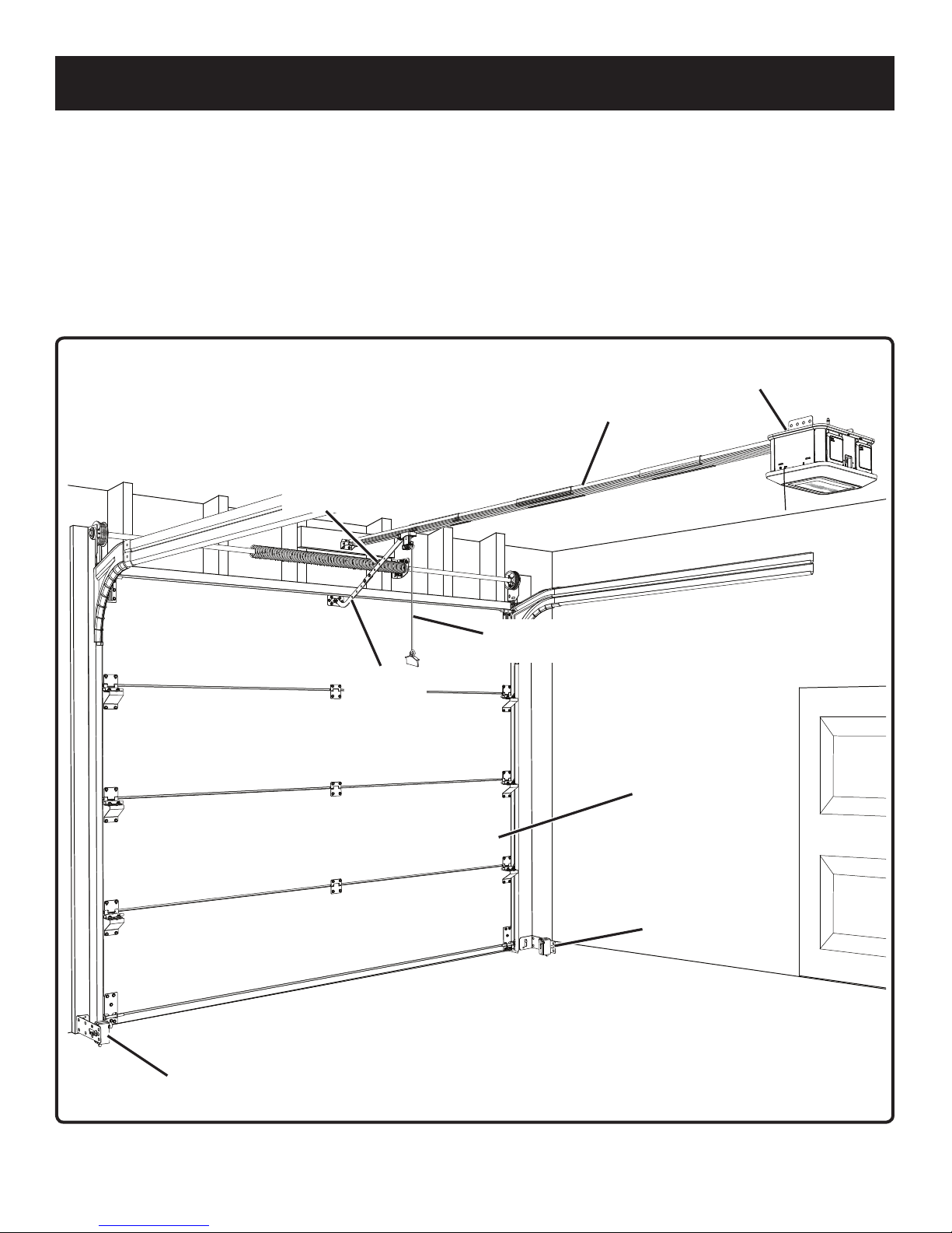
Mount the garage door opener to joists only. Never mount
the unit to drywall or false ceiling grids. Failure to properly
install the garage door opener could result in a falling
hazard that can cause death or serious personal injury.
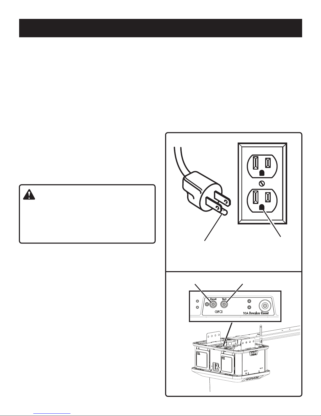
This product is not equipped for permanent wiring.
Contact licensed electrician to install a suitable receptacle
if one is not available.
Plug the garage door opener directly into a power source.
Do not attach an extension cord or cord adaptor to this
product’s power cord.
Do not unplug by pulling on cord. To unplug, grasp the
plug, not the cord.
Do not handle power supply cord, wires, wire terminals,
or accessories with wet hands.
Unplug the garage door opener before making any
adjustments, changing accessories, or performing
maintenance. Such preventive safety measures reduce
the risk of electrocution or electric shock.
Inspect power supply cord and wires periodically and,
if damaged, have repaired by the manufacturer to avoid
risk. Keep power supply cord and wires away from pinch
points and moving parts. Following this rule will reduce
the risk of electric shock or fire.
Check damaged parts. Before further use of the garage
door opener, a belt, pulley, or other part that is damaged
should be carefully checked to determine that it will
operate properly and perform its intended function.
Check for alignment of moving parts, binding of moving
parts, breakage of parts, and any other conditions that
may affect its operation. A belt, pulley, or other part that
is damaged should be properly repaired or replaced by
the manufacturer. Following this rule will reduce the risk
of shock, fire, or serious injury.
When servicing a product, use only identical replacement
parts. Follow instructions in the Maintenance section of
this manual. Use of unauthorized parts or failure to follow
Maintenance instructions may create a risk of injury.
Never attempt to loosen, adjust, or remove the door
springs (torsion spring and/or extension spring), door
spring components, or any surfaces to which these items
are secured. These items are under extreme tension and
any such alteration could result in death, serious personal
injury, and/or property damage.
Servicing of garage doors, door springs (torsion and/or
extension springs), and door spring components should
be performed only by a qualified service person.
To prevent SERIOUS INJURY or DEATH, DO NOT open
garage door if fire is present unless you must escape
through it. CALL 911 or the fire department. Opening the
garage door will introduce fresh air and may cause fire to
spread rapidly.
SPECIFIC SAFETY RULES

4 - English
Your garage door opener can be operated remotely on
the smartphone app.
The communication distance (range) between your
garage door opener and your Wi-Fi router may be 100
feet (30 meters) inside your home. A number of factors in
and around your home may reduce this range including
the number of floors, number/size of rooms, furniture
and types of building materials used for construction.
Examples may include suspended ceilings, ductwork,
large metallic appliances (refrigerators), and metal studs.
Interference from these factors in your home can be
overcome by adding Wi-Fi signal boosters to extend the
range of the wireless signal from your router in your home.
NOTE:
1.The range and proper operation of any wireless device
will vary depending on factors in and around your home.
2.Your garage door opener may not transmit between
buildings. If you have a detached garage, your garage
door opener may not communicate properly with your
Wi-Fi router.
3.Metal objects (e.g. wall studs) and metallic wallpaper may
interfere with the signal from your Garage Door Opener.
You will need to test your Garage Door Opener after any
changes to your home or garage including remodeling,
moving furniture, and installing new appliances or devices
that communicate with your Wi-Fi router.
NOTICE:
It is important that the wireless signal from your router is
secured. An unsecured signal could allow unauthorized
access to devices communicating on your home network,
including your garage door opener.
Since the 1990s, security algorithms have been used
to encrypt and protect wireless signals. The two most
commonly used algorithms are WEP and WPA/WPA2.
• WEP (Wired Equivalent Privacy) is the oldest and most
widely used security algorithm. Despite its popularity,
this algorithm is the most susceptible to hacking. The
network passwords used to protect WEP networks
have to be exactly 10 or 26 characters long and
can only include hexadecimal characters (a-f and
0-9). By modern standards, passwords with these
limitations are not complex enough to offer adequate
security. In 2005, the Federal Bureau of Investigation
demonstrated WEP’s vulnerabilities by easily cracking
WEP passwords using publicly available software.
Due to serious security concerns, your garage
door opener will not connect to routers using WEP
network security. Refer to your router’s operator’s
manual to change the security type to WPA/WPA2.
• WPA/WPA2 (Wi-Fi Protected Access) was created
as a safer alternative to WEP. The cryptographic
technology in this algorithm is far superior to that of its
predecessor. WPA/WPA2 passwords can be up to 63
characters long and include hexadecimal characters
as well as any printable ASCII characters (a-z, 0-9,
punctuation marks, and some glyphs). Although it
offers greater protections, WPA/WPA2 networks can
still be vulnerable if weak passwords are used. Always
use a strong password that includes upper and lower
case letters, punctuation marks, numbers, and glyphs
(if supported) to reduce the risk of the password being
cracked or guessed by unauthorized parties.
WI-FI COMMUNICATION INFORMATION

5 - English
The following signal words and meanings are intended to explain the levels of risk associated with this product.
SYMBOL SIGNAL MEANING
DANGER: Indicates a hazardous situation, which, if not avoided, will result in death or
serious injury.
WARNING: Indicates a hazardous situation, which, if not avoided, could result in death or
serious injury.
CAUTION: Indicates a hazardous situation, that, if not avoided, may result in minor or
moderate injury.
NOTICE: (Without Safety Alert Symbol) Indicates information considered important, but
not related to a potential injury (e.g. messages relating to property damage).
Some of the following symbols may be used on this product. Please study them and learn their meaning. Proper
interpretation of these symbols will allow you to operate the product better and safer.
SYMBOL NAME DESIGNATION/EXPLANATION
Safety Alert Indicates a potential personal injury hazard.
Read Operator’s
Manual
To reduce the risk of injury, user must read and understand operator’s
manual before using this product.
Eye Protection Alwayswear eyeprotectionwithsideshieldsmarkedtocomplywithANSI
Z87.1 when assembling and performing maintenance on this product.
Electrocution/
Electric Shock
Unplug the unit before attaching wires to reduce the risk of electrocution
or electric shock.
Moving Door
To avoid death or serious personal injury, stay clear of the garage door
while it is moving and never attempt to run or walk under moving garage
door.
AWi-Fi routerconnected
to the internet in your
home is required to use
the app.
You will not be able to open your garage door or receive other information
from the accessories using the Ryobi Garage Door Opener Accessory
System App if your home’s Wi-Fi connection with your garage door
opener is not connected or functioning properly.
SYMBOLS

6 - English
Some of the following symbols may be used on this product. Please study them and learn their meaning. Proper in-
terpretation of these symbols will allow you to operate the product better and safer.
SYMBOL NAME DESIGNATION/EXPLANATION
Direct Current Type or a characteristic of current
Alternating Current Type of current
n
o
No Load Speed Rotational speed, at no load
.../min Per Minute Revolutions, strokes, surface speed, orbits etc., per minute
V Volts Voltage
Hz Hertz Frequency (cycles per second)
A Amperes Current
W Watt Power
CALIFORNIA PROPOSITION 65
WARNING:
This product may contain chemicals, including lead, known to the State of California to cause cancer, birth defects or
other reproductive harm. Wash hands after handling.
SYMBOLS

7 - English
GFCI receptacles do not protect against short circuits,
overloads, or shocks.
The GFCI receptacle can be tested with the TEST and
RESET buttons.
To test:
Locate the TEST and RESET buttons on the top of the
power head.
Depress the TEST button. This should cause the RESET
button to pop out.
To restore power, depress the RESET button.
Perform this test monthly to ensure proper operation of the
GFCI.
ELECTRICAL CONNECTION
This product has a precision-built electric motor. It should be
connected to a power supply that is nominal 120V/60Hz
AC (typical U.S. household circuit). Do not operate this
product on direct current (DC). A substantial voltage drop
will cause a loss of power and the motor will overheat. If
the product does not operate when plugged into an outlet,
double-check the power supply.
GROUNDING INSTRUCTIONS
See Figure 1.
This product must be grounded. In the event of a malfunction
or breakdown, grounding provides a path of least resistance
for electric current to reduce the risk of electric shock.
This product is equipped with an electric cord having an
equipment-grounding conductor and a grounding plug. The
plug must be plugged into a matching outlet that is properly
installed and grounded in accordance with all local codes
and ordinances.
Do not modify the plug provided. If it will not fit the outlet,
have the proper outlet installed by a qualified electrician.
WARNING:
Improper connection of the grounding plug can result in a
risk of electric shock. When repair or replacement of the
cord is required, do not connect the grounding wire to
either flat blade terminal. The wire with insulation having
an outer surface that is green with or without yellow
stripes is the grounding wire.
Check with a qualified electrician or service personnel if the
grounding instructions are not completely understood, or if
in doubt as to whether the product is properly grounded.
Repair or replace a damaged or worn cord immediately.
This product is for use on a nominal 120 V circuit and has a
grounding plug similar to the plug illustrated in figure 1. Only
connecttheproductto anoutlet havingthesame configuration
as the plug. Do not use an adapter with this product.
GROUND FAULT CIRCUIT INTERRUPTER
See Figure 2.
The 10 amp, 120 volt receptacle on the garage door opener
is protected by a Ground Fault Circuit Interrupter (GFCI),
which guards against the hazards of ground fault currents.
An example of ground fault current is the current that would
flow through a person who is using an appliance with faulty
insulation and, at the sametime, is in contact with an electrical
ground such as a plumbing fixture, wet floor, or earth.
Grounding
Pin
120 V
Grounded
Outlet
Fig. 1
Fig. 2
ELECTRICAL
Reset Test

8 - English
PRODUCT SPECIFICATIONS
Accessory Capacity ................................................up to 4
Max. Garage Door Height ...........................................7 ft.*
Bulb Type .................................................................... LED
Drive Type .......................................................... Belt Drive
Input ..........................................................120V AC, 60 Hz.
Motor.................................................................1.25 HPs**
No Load Speed ................................................90-98 RPM
Rail Length .................................................................10 ft.
Remote Detection Range .........................................300 ft.
Vehicle and Home ..................... HomeLink®compatible***
* Extension kits are available.
** Horsepower Similar (HPs) designates that this system meets RYOBI
pulling force specification for a 1.25 horsepower garage door opener.
*** HomeLink®and the HomeLink®house icon are registered trademarks
of Gentex Corporation.
FEATURES
Fig. 3
Straight
Door Arm
Curved
Door Arm
Emergency
Release Rope
Rail
Assembly
Power
Head
Safety
Sensor
Safety
Sensor
Garage
Door

9 - English
Fig. 4
RF
Antenna
AC
Receptacle
Brackets
Rail
Assembly
Wi-Fi
Antenna
Accessory
Port Cover
FEATURES
Accessory
Port #4
Accessory
Port #3
Accessory
Port #1
Accessory
Port #2
Test
Reset
Circuit
Breaker

10 - English
Fig. 5
Light
Cover
Indoor Keypad
Safety Sensor (2) Car Remote (2)
FEATURES
Wire
Terminal
(Sensor)
Wire
Terminal
(Keypad)
Set
Wi-Fi Down
Program Up

11 - English
KNOW YOUR GARAGE DOOR OPENER
See Figures 3 - 5.
The safe use of this product requires an understanding of the
information on the product and in this operator’s manual as
well as a knowledge of the project you are attempting. Before
use of this product, familiarize yourself with all operating
features and safety rules.
AC RECEPTACLE
The garage door opener has a 120 Volt AC, GFCI protected
receptacle with a rating of 10 Amps. It can be used for
operatingAC garage dooraccessories aswell asappropriate
appliances, electrical lighting, and tools.
ACCESSORY PORTS
Your garage door opener has four ports for operating DC
garage door accessories.
ANTENNAS
The Wi-Fi and RF antennas allow the garage door opener
to communicate with the smartphone app, car remotes,
and keypads.
AUTOMATIC REVERSAL SYSTEM
When a closing garage door contacts an object that is
1-1/2 in. above the garage floor, the automatic reversal
system will stop and raise the door to the fully open position.
BELT DRIVE SYSTEM
This product is equipped with a belt drive system that is
quieter than traditional chain-drive models.
CAR REMOTES
Convenient car remotes allow you to activate the garage
door opener from a distance of up to 300 ft. The remotes
are equipped with a visor clip, so you can store them on
your car’s sun visor.
CIRCUIT BREAKER
The circuit breaker is provided to protect the AC accessories
against electrical overload. The circuit breaker may be reset
by pressing the circuit breaker reset button.
EMERGENCY RELEASE ROPE
In the case of an emergency or entrapment, pulling the
emergency release rope will allow you to manually raise a
closed garage door.
HomeLink®COMPATIBILITY
Features on your garage door opener can be controlled by
cars and homes equipped with HomeLink®control systems.
HomeLink®and the HomeLink®house icon are registered trademarks of
Gentex Corporation.
INDOOR KEYPAD
The indoor keypad is installed on the interior of the garage
and can be used to open and close the garage door, activate
the accessory ports, and turn the LED lights on and off.
LED LIGHTS
LED lights are located beneath the light cover and illuminate
whenever the motor is running or the LIGHT () button on
the indoor keypad is pressed. To turn the LED lights off,
press the LIGHT ( ) button.
NOTE: By default, the LED lights will illuminate for three
minutes after the LIGHT () button is pressed or after the
power head starts opening or closing the garage door. The
time can be adjusted in one minute increments, between
one and ten minutes, using the RYOBI Garage Door Opener
Accessory System App.
RAIL SYSTEM
The ergonomic rail design makes assembly and installation
quick and easy.
SAFETY SENSORS
Your garage door opener comes with two sensors that cast
an invisible light beam across the opening of your garage.
If an object crosses the path of the beam while the garage
door is closing, the door will automatically stop and reverse
to the fully open position.
SMARTPHONE COMPATIBILITY
The garage door opener can be operated remotely with a
smartphoneusing theRYOBIGarage DoorOpenerAccessory
System App. For more information, visit ryobitools.com or
download the app from the App Store or Google Play Store.
VACATION MODE
To enter and exit vacation mode, press and hold the LOCK
() button on the indoor keypad for one second. When in
vacationmode, thegaragedoor openercanonly becontrolled
by the indoor keypad and smartphone app.
FEATURES

12 - English
LOOSE PARTS
A B C
D
E F
G
H I J K
L M N O
P
S
U
V
W
Y
Z
X
T
Q
R
aa
bb ee
ff
gg
hh
ii
jj
kk
ll
cc
dd
Child can become trapped or pinned under an automatic garage door resulting
in serious injury or death.
• Do not allow children to walk or run under a closing door.
• Do not allow children to operate door opener controls.
• Always keep a closing door within sight.
• In the event a person is trapped under the door, push the control button or
use the emergency release.
• This operator system is equipped with an unattended operation feature. The
door could move unexpectedly. Not intended for use with single panel garage
doors.
Testdoor opener monthly:
• Refer to Operator’s Manual.
• Use a 1 ½ inch thick object (or 2 X 4 laid flat) placed on the floor under the
closing door.
• In the event the door does reverse upon contact, adjust, repair, or replace the
opener.
Do not remove or paint over this label.
Mount this label next to the wall control.
Mount the wall control out of the reach of children at least 5 feet above the floor.
Fig. 6

13 - English
LOOSE PARTS
The following items are included with your garage door opener:
A. Header Bracket..................................................................................................................................................... 1
B. Wing Nut............................................................................................................................................................... 2
C. Mounting Strap..................................................................................................................................................... 2
D. Door Bracket......................................................................................................................................................... 1
E. Curved Door Arm.................................................................................................................................................. 1
F. Straight Door Arm................................................................................................................................................. 1
G. Emergency Release Rope .................................................................................................................................... 1
H. Large Clevis Pin.................................................................................................................................................... 1
I. Medium Clevis Pin................................................................................................................................................ 1
J. Small Clevis Pin .................................................................................................................................................... 1
K. Bracket ................................................................................................................................................................. 2
L. Hitch Pin ............................................................................................................................................................... 3
M. Sleeve ................................................................................................................................................................... 3
N. Outer Trolley.......................................................................................................................................................... 1
O. Entrapment Warning Label (Eng., Fr., and Sp.) .................................................................................................... 3
P. Support Rail.......................................................................................................................................................... 3
Q. End Rail Assembly................................................................................................................................................ 1
R. Sensor Bracket ..................................................................................................................................................... 2
S. Safety Sensor ....................................................................................................................................................... 2
T. Pulley Rod Assembly............................................................................................................................................ 1
U. Power Head .......................................................................................................................................................... 1
V. Car Remote........................................................................................................................................................... 2
W. Indoor Keypad ...................................................................................................................................................... 1
X. Sprocket ............................................................................................................................................................... 1
Y. Front Brace........................................................................................................................................................... 1
Z. Nut (7/16 in.) ....................................................................................................................................................... 10
aa. Bolt (7/16 in. x 3/4 in.)........................................................................................................................................... 6
bb. Lag Screw (7/16 in. x 1-1/2 in.)............................................................................................................................. 2
cc. Self-tapping Screw ............................................................................................................................................... 2
dd. Lock Nut (1/2 in.) .................................................................................................................................................. 2
ee. Bolt (1/2 in. x 1 in.)................................................................................................................................................ 2
ff. Nail (2 in.) .............................................................................................................................................................. 2
gg. Screw (1 in., Phillips Hd.)...................................................................................................................................... 2
hh. Washers (7/16 in.) ................................................................................................................................................. 6
ii. Drywall Anchor...................................................................................................................................................... 2
jj. Insulated Staple.................................................................................................................................................. 30
kk. Lag Screw (1/2 in. x 1-1/2 in.)............................................................................................................................... 2
ll. Screw (1-1/2 in., Phillips Hd.) ............................................................................................................................... 2

14 - English
The following tools (not included or drawn to scale) are needed for assembly and adjustments:
UNPACKING
This product requires assembly.
Carefully remove the product and any accessories from
the box. Make sure that all items listed in the loose parts
list are included.
NOTE: This tool is heavy. To avoid back injury, lift with
your legs, not your back, and get help when needed.
WARNING:
Do not use this product if any parts on the Loose Parts List
are already assembled to your product when you unpack
it. Parts on this list are not assembled to the product by
the manufacturer and require customer installation. Use
of a product that may have been improperly assembled
could result in serious personal injury.
Inspect the tool carefully to make sure no breakage or
damage occurred during shipping.
Do not discard the packing material until you have
carefully inspected and satisfactorily operated the tool.
If any parts are damaged or missing, please call
1-877-205-5714 for assistance.
WARNING:
If any parts are damaged or missing do not operate this
tool until the parts are replaced. Use of this product
with damaged or missing parts could result in serious
personal injury.
WARNING:
Do not attempt to modify this tool or create accessories
not recommended for use with this tool. Any such
alteration or modification is misuse and could result in a
hazardous condition leading to possible serious personal
injury.
WARNING:
Do not connect to power supply until assembly is
complete. Failure to comply could result in accidental
starting and possible serious personal injury.
Fig. 7
6 or 7 Foot
A-Frame Ladder
Drill
Socket Bit (7/16,
3/8, and 1/2 in.)
3/16 in.
Drill Bit
PliersTape Measure
Flat Head
Screwdriver
Phillips Head
Screwdriver
Adjustable
Wrench
Level
Pencil
Hammer
Hacksaw
2 x 4 board (1 ft.)
Rubber
Mallet
Socket Wrench
(7/16, 3/8, and 1/2 in.) Wire
Stripper
TOOLS NEEDED
ASSEMBLY

15 - English
ASSEMBLY
WARNING:
Always wear eye protection with side shields marked
to comply with ANSI Z87.1 when assembling and
performing maintenance on this product. Failure to do
so could result in objects being thrown into your eyes
resulting in possible serious injury.
NOTICE:
Many of the illustrations in this manual show only portions
of the garage door opener. This is intentional so that we
can clearly show points being made in the illustration.
Never operate the garage door opener without all parts
securely in place and in good operating condition.
WARNING:
Confirm that the inner trolley is in the orientation shown
in Figure 10. An incorrectly installed inner trolley could
result in the garage door opener operating in the opposite
direction from its intended movement and result in death
or serious personal injury from the moving garage door.
ASSEMBLING THE RAILS
See Figures 8 - 18.
Locate the following items:
Front Brace
End Rail Assembly
Support Rail (3)
Sleeves (3)
Pulley Rod Assembly
Outer Trolley
Remove tie wrap from end rail and pulleys.
Insert rear pulley into end rail. Slide together until pulley
is snug against the rail.
Pull the front pulley and belt through the end rail and into
a sleeve.
Slide the outer trolley into the end rail.
Pull the release lever down and move outer trolley toward
the inner trolley until they are engaged.
Sleeve
End
Rail
Fig. 9
Fig. 8
Fig. 10
Fig. 11
End
Rail
End
Rail Rear
Pulley
Front
Pulley Belt
Outer
Trolley
Release
Lever
Outer
Trolley
Outer
Trolley
Inner
Trolley
Inner Trolley

16 - English
Insert the edge of the end rail into the sleeve. Slide
together until rail clicks into place. If you cannot get the
rail to fit by hand, try gently tapping it with a rubber mallet
until it is snug and clicks into place. Be careful not to
pinch or damage the belt.
Repeat this process to attach a support rail, second
sleeve, second support rail, third sleeve, and then the
the third support rail. When assembled correctly, the rails
should not separate easily when pulled.
Pull the front pulley and belt through the top of the rail
assembly.
Turn the tension nut on the pulley rod counterclockwise
to loosen. Remove the tension nut and spring from the
pulley rod.
Insert the pulley rod into the front pulley.
NOTE: Ensure the head of the rod is fully seated in the
pulley.
Move the front pulley back into the rail assembly.
ASSEMBLY
Insert the edge of the front brace into the rail assembly.
Slide together until brace clicks in place. If you cannot
get the brace to fit by hand, try gently tapping it with a
rubber mallet until it is snug.
Pull the front pulley forward and slide the rod through the
hole in the brace.
Install spring and tension nut onto pulley rod.
Move the inner and outer trolley to the middle of the rail
assembly.
Sleeve Sleeve
Sleeve
Tension
Nut
Spring
Fig. 16
Fig. 14
Fig. 15
Fig. 17
Support
Rail
Support
Rail Front
Pulley
Front
Brace
Fig. 18
Pulley
Rod
Pulley
Rod
Tension
Nut
Spring
Front
Brace Support
Rail
Front
Pulley
Support
Rail
Sleeve
Sleeve Sleeve
End
Rail
Fig. 12
Fig. 13
Support
Rail

17 - English
Fig. 20
Fig. 19
Tighten
Loosen
3/8 in. to
1/2 in.
Base of
the nut
Edge of
the brace
Rail
Edge
CENTER OF RAIL ASSEMBLY
ATTACHING RAIL ASSEMBLY TO POWER
HEAD
See Figures 22 - 25.
Locate the following items:
Power Head
Bracket (2)
Nut (7/16 in.) [4]
Sprocket
Rail Assembly
Place the power head on a towel or the packaging material
with the light cover facing down. Do not place the unit
directly on hard surfaces as this may damage the light
cover.
Place the sprocket onto the motor shaft with the round
side of the sprocket facing up.
Fig. 21
Fig. 22
Belt
1/8 in.
Gap
Sprocket
Round
Side
ADJUSTING THE BELT TENSION
See Figures 18 - 21.
Using a 1/2 in. socket, turn the tension nut clockwise
to tighten the belt and counter-clockwise to loosen it.
Adjust the nut until there is approximately 3/8 to 1/2 in.
of exposed thread showing above it or until the base of
the nut is aligned with the edge of the brace.
When properly tensioned, there should be about a
1/8 in. gap between the belt and the edges of the rail near
the center of the rail assembly.
ASSEMBLY
Shaft

18 - English
Hold the rail assembly above the sprocket on the power
head.
Rotate the rail assembly until the opening in the rail is
aligned with the sprocket.
Lower the rail assembly onto the sprocket with the
channel (open end) facing down. Slowly rotate the rail to
the correct orientation as you lower it into position.
When installed correctly, the teeth on the sprocket should
engage the rail assembly and the rail should sit flat on the
power head.
Place the brackets on top of the studs, and over the end
rail.
Place nuts onto the studs and tighten using a 7/16 in.
socket. Do not overtighten.
Remove the tape securing the Wi-Fi antenna and raise it
to an upright position to ensure the best Wi-Fi signal.
NOTE: Ensure that the antenna is screwed into the power
head securely.
ASSEMBLY
Fig. 24
Fig. 23
Fig. 25
Front of
Power Head
Nut
Nut
Bracket
Stud
Stud
Sprocket
Stud
Wi-Fi
Antenna

19 - English
IMPORTANT
INSTALLATION
INSTRUCTIONS
WARNING:
TO REDUCE THE RISK
OF SEVERE INJURY
OR DEATH:
1. READ AND FOLLOW ALL INSTALLATION
INSTRUCTIONS.
2. Install only on a properly balanced garage door. An
improperly balanced door could cause severe injury.
Have a qualified service person make repairs to
cables, spring assemblies, and other hardware before
installing opener.
3. Remove all ropes and remove or make inoperative all
locks connected to the garage door before installing
opener.
4. Where possible, install door opener 7 feet or more
above the floor. For products having an emergency
release, mount the emergency release within reach,
but at least 6 feet above the floor and avoiding contact
with vehicles to avoid accidental release.
5. Do not connect opener to source of power until
instructed to do so.
6. Locate control button: (a) within sight of door, (b) at
a minimum height of 5 feet so small children cannot
reach it, and (c) away from all moving parts of the door.
7. Install Entrapment Warning Label next to the control
button in a prominent location. Install the Emergency
Release Marking. Attach the marking on or next to the
emergency release.
8. After installing opener, the door must reverse when it
contacts a 1-1/2 inch high object (or a 2 by 4 board
laid flat) on the floor.
9. WARNING: To reduce the risk of injury to persons -
Only enable the unattended operation feature when
installed on a sectional door.
WARNING:
To reduce the risk of injury to persons – Only enable the
RYOBI Garage Door Opener Accessory System App
feature when installed with a sectional door.
WARNING:
Do not connect the garage door opener to a power supply
during installation unless specifically instructed to do so.
Failure to comply could result in accidental starting and
possible serious personal injury.
WARNING:
To avoid serious personal injury, make sure the garage
door opener is mounted to joists. Never mount the unit
to drywall or false ceiling grids.
WARNING:
Always wear eye protection with side shields marked to
comply with ANSI Z87.1 when installing this product.
Failure to do so could result in objects being thrown into
your eyes resulting in possible serious injury.
NOTICE:
Many of the illustrations in this manual show only portions
of the garage door opener. This is intentional so that we
can clearly show points being made in the illustration.
Never operate the garage door opener without all parts
securely in place and in good operating condition.
WARNING:
If you feel uncomfortable performing any of the
installation steps described in this manual, have the
installation performed by a qualified service person.
Improper installation of the garage door opener can result
in death, serious personal injury, or property damage.
INSTALLATION

20 - English
Torsion Spring Extension Spring
WARNING:
Many of the steps described in this INSTALLATION
section require the use of a ladder. Use extreme care
when standing on a ladder. Ensure someone is holding
the ladder on the ground to keep it stable. Failure to
safely use a ladder can cause a fall and result in death
or serious personal injury.
CHECK THE CONDITION OF THE DOOR AND
IDENTIFY THE SPRING TYPE
See Figure 26 - 28.
WARNING:
If the garage door does not move smoothly, binds, or is
out of balance, have it repaired or replaced by a qualified
service person. An unbalanced or damaged garage door
may not reverse on command, which can result in death
or serious personal injury.
NOTICE:
The garage door opener may not function as intended if
installed onto an unbalanced garage door.
Remove any ropes attached to the garage door.
Disable any and all door locks.
Raise and lower the door to ensure it moves smoothly.
Check the balance of the door. Raise the door until it is
half open and release it. If properly balanced, the door
will remain in this position without moving.
NOTE: For single-panel garage doors, balance can be
checked at two additional positions. Raise the door until it
is nearly in the fully open position (about shoulder height)
and release it. If properly balanced, the door should
move to the fully open position. Lower the door until it
is nearly in the fully closed position (about knee height).
If properly balanced, the door should move to the fully
closed position.
If the door does not move smoothly, binds, or is out of
balance, this could indicate a problem with the door, door
springs (torsion spring and/or extension spring), or door
spring components. Have the garage door or door springs
repaired by a qualified service person before installing the
garage door opener.
Fig. 26
Fig. 27
Fig. 28
Sectional
Door
Single-Panel
Door
Half-Open
Position
Half-Open
Position
INSTALLATION
Table of contents
Languages:
Other Ryobi Garage Door Opener manuals
Popular Garage Door Opener manuals by other brands

RIB
RIB SUPER 2200 FAST installation instructions

Craftsman
Craftsman 139.53664SRT2 owner's manual

Safe Fleet
Safe Fleet R O M IV Series installation instructions

Aprimatic
Aprimatic XT2500/XL INSTRUCTIONS AND RECOMMENDATIONS FOR THE INSTALLER

Nice
Nice Linear 661 user guide

CAME
CAME AXI SWN20 installation manual