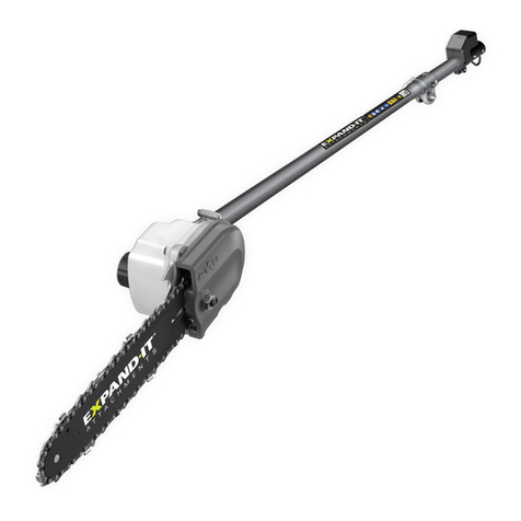
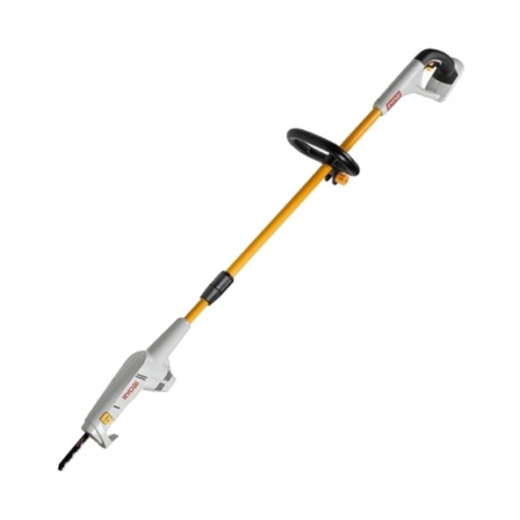
Ryobi APR04A User manual

OPERATOR’S MANUAL
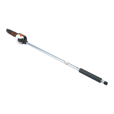
PRUNER ATTACHMENT
APR04A
SAVE THIS MANUAL FOR FUTURE REFERENCE
Your pruner attachment has been engineered and manufactured to our high standard for dependability, ease of operation,
and operator safety. When properly cared for, it will give you years of rugged, trouble-free performance.
WARNING: To reduce the risk of injury, the user must read and understand the operator’s manual before using
this product.
Thank you for your purchase.

1
WARNING:
Read and understand all instructions. Failure to
follow all instructions listed below, may result in electric
shock, re, and/or serious personal injury.
SAVE THESE INSTRUCTIONS
Read these instructions and the instructions for the power
head thoroughly before using pruner.
Know the tool. Read and understand the operator’s
manual and observe the warnings and instruction labels
afxed to the tool.
Do not allow children or untrained individuals to use this
unit.
Wear safety glasses / goggles and hearing protection that
are marked to comply with standards when operating this
product.
Wear heavy long pants, boots, and gloves. Do not wear
loose tting clothing, short pants, jewelry of any kind, or
go barefoot.
Secure long hair so it is above shoulder level to prevent
entanglement in any moving parts.
Keep all bystanders, children, and pets at least 15 m
away.
Stay alert, watch what you are doing, and use common
sense when operating a power tool. Do not use tool while
tired or under the inuence of drugs, alcohol, or medica-
tion. A moment of inattention while operating power tools
may result in serious personal injury.
Do not operate in poor lighting.
Do not overreach. Keep proper footing and balance at all
GENERAL SAFETY RULES
times. Proper footing and balance enables better control
of the tool in unexpected situations.
Keep all parts of your body away from any moving part.
Do not touch areas around the mufer or cylinder of the
power head. These parts get hot from operation. Failure to
heed this warning could result in possible serious personal
injury.
Always stop the engine and remove the spark plug wire
and/or ensure that the engine cut off switch remains in
the off position before making any adjustments or repairs
except for carburetor adjustments.
Inspect unit before each use for loose fasteners and
damaged or missing parts. Correct before using the
attachment. Failure to do so can cause serious injury.
Use only original manufacturer’s replacement parts. Fail-
ure to do so may cause poor performance, possible injury,
and will void your warranty.
Do not, under any circumstance, use any attachment or
accessory on this product, which was not provided with
the product, or identied as appropriate for use with this
product in the operator’s manual.
Avoid dangerous environments. Do not use the attachment
in damp or wet locations. Do not use in rain.
Use the right attachment. Do not use attachment for any
job except that for which it is intended.
Keep hands away from cutting area. Keep hands away
from the cutting chain. Do not reach underneath, work
around or over the cutting chain while the chain is rotating.
Do not attempt to remove cut material whilst the cutting
chain is moving.
The cutting chain may coast momentarily after the power
head has been turned off.
Kickback is a dangerous reaction that can lead to serious
injury. Kickback may occur when the moving chain con-
tacts an object at the upper portion of the tip of the guide
bar or when the wood closes in and pinches the chain
in the cut. Contact at the upper portion of the tip of the
guide bar can cause the chain to dig into the object and
stop the chain for an instant. The result is a lightning fast,
reverse reaction which kicks the guide bar up and back
toward the operator. If the chain is pinched along the top
of the guide bar, the guide bar can be driven rapidly back
toward the operator. Either of these reactions can cause
loss of tool control which can result in serious injury. Do
not rely exclusively upon the safety devices built into the
tool. As a pruner user, you should take several steps to
keep your cutting jobs free from accident or injury.
SPECIFIC SAFETY RULES
With a basic understanding of kickback, you can reduce
or eliminate the element of surprise. Sudden surprise
contributes to accidents.
Make sure that the area in which you are cutting is free
from obstructions. Do not let the nose of the guide bar
contact a log, branch, fence, or any other obstruction while
you are operating the unit.
Always cut with the engine running at full speed. Fully
squeeze the throttle trigger and maintain a steady cutting
speed.
Follow the sharpening and maintenance instructions for
the chain.
Use only the replacement guide bars and low kickback
chains specied for this unit.
INTRODUCTION
This product has many features for making its use more pleasant and enjoyable. Safety, performance, and dependability
have been given top priority in the design of this product making it easy to maintain and operate.


2
SYMBOLS
Some of the following symbols may be used on this product. Please study them and learn their meaning. Proper
interpretation of these symbols will allow you to operate the product better and safer.
SYMBOL NAME EXPLANATION
Safety Alert Symbol Precautions that involve your safety.
Read the Operator’s Manual To reduce the risk of injury, user must read and understand
operator’s manual before using this product.
Eye, Hearing and Head Protection Wear eye and hearing protection which is marked to comply
with standards when operating this equipment.
Safety Footwear Wear non-slip safety footwear when using this equipment.
Gloves Wear non-slip, heavy-duty protective gloves when handling
the pole pruner attachment and the saw chain.
Moving Parts Keep hands away from moving parts.
Kickback DANGER! Beware of kickback.
Hot Surfaces Indicates HOT SURFACES. Keep all body parts away from
all hot surfaces.
Risk of Electrocution DANGER! Risk of electrocution! Keep attachment within 15m
of overhead electrical lines.
Do not force tool. Use the correct tool for your application.
The correct tool will do the job better and safer at the rate
for which it is designed.
Do not use on a ladder or unstable support. Stable foot-
ing on a solid surface enables better control of the tool in
unexpected situations.
Never let anyone use the tool who has not received ad-
equate instructions in its proper use. This also applies tho
the power head that drives the attachment.
To protect yourself from electrocution, do not operate the
pole pruner attachment within 15m of overhead electrical
lines.
To protect yourself from falling branches, do not stand
directly under the branch or limb being cut. This unit should
not be held at an angle over 60° from ground level.
SPECIFIC SAFETY RULES
Keep the handles dry, clean, and free of oil or fuel mix-
ture.
Before you start the engine, make sure the chain is not
contacting any object.
Shut off the engine and make sure the cutting chain has
stopped before setting the unit down.
To prevent electrical shock or serious personal injury,
exercise extreme caution when using this product with
any electrical power head. Refer to power head operators
manual for suitability of attachment.
Save these instructions. Refer to them frequently and
use them to instruct others who may use this tool.
If you loan someone this tool, loan them these in-
structions also to prevent misuse of the product and
possible injury.

3
SERVICE
Servicing requires extreme care and knowledge and should
be performed only by a qualied service technician. For
service we suggest you return the product to your nearest
AUTHORISED SERVICE CENTRE for repair. When
servicing, use only identical replacement parts.
WARNING:
To avoid serious personal injury, do not attempt to use
this product until you read thoroughly and understand
completely the operator’s manual. If you do not understand
the warnings and instructions in the operator’s manual,
do not use this product. Call Ryobi customer service for
assistance.
The following signal words and meanings are intended to explain the levels of risk associated with this product.
SYMBOL SIGNAL MEANING
DANGER: Indicates an imminently hazardous situation, which, if not avoided, will result in
death or serious injury.
WARNING: Indicates a potentially hazardous situation, which, if not avoided, could result in
death or serious injury.
CAUTION: Indicates a potentially hazardous situation, which, if not avoided, may result in
minor or moderate injury.
CAUTION: (Without Safety Alert Symbol) Indicates a situation that may result in property
damage.
SYMBOLS
WARNING:
SAVE THESE INSTRUCTIONS
The operation of any power tool can result in foreign objects being thrown into your eyes, which can result
in severe eye damage. Before beginning power tool operation, always wear safety goggles or safety
glasses with side shields and, when needed, a full face shield. We recommend Wide Vision Safety Mask
for use over eyeglasses or standard safety glasses with side shields. Always use eye protection which
is marked to comply with standards.
FEATURES
PRODUCT SPECIFICATIONS
Bar length ............................................................... 254 mm
Weight ..................................................................... 2.05 kg
KNOW YOUR PRUNER ATTACHMENT
See Figure 1.
The safe use of this product requires an understanding of the
information on the product and in this operator’s manual as
well as a knowledge of the project you are attempting. Before
use of this product, familiarize yourself with all operating
features and safety rules.

4
To install the attachment:
Remove the hanger cap from the attachment shaft.
Loosen the knob on the coupler of the power head
shaft.
Push in the button located on the shaft of the pruner at-
tachment.
Align the button with the guide recess on the extension shaft
coupler and slide the two shafts together. Rotate extension
shaft until button locks into the positioning hole.
NOTE: The attachment should only be operated with the
bar in a vertical position (when the unit is in use). If the
button does not release completely in the positioning hole,
the shaft is not locked into place. Slightly rotate from side
to side until the button is locked into place.
Tighten the knob securely.
Repeat previous steps to attach extension shaft to power
head.
WARNING:
Be certain the knob is fully tightened before operating
equipment; check it periodically for tightness during use
to avoid serious injury.
To remove:
Stop the engine.
Loosen the knob.
Push in the button and twist the shafts to remove and
separate ends.
INSTALLING THE SHOULDER STRAP AND
STRAP HANGER
See Figures 3 - 4.
When operating this unit, you must wear a shoulder strap
to support the unit. If your unit does not have a strap
hanger installed on the power head shaft, use the following
instructions to install the hanger.
Pull strap hanger apart and place over power head end
of shaft; position near the upper knob.
Install bolt and lock nut. Tighten nut securely.
NOTE: Check for tightness before each use to avoid seri-
ous injury or product damage.
Place shoulder strap over your left shoulder and attach
shoulder strap clip to strap hanger. Adjust by sliding the
front clip up or down.
NOTE: When properly adjusted, the power head should
be supported by the shoulder strap about hip level.
UNPACKING
This product requires assembly.
Carefully remove the items from the box. Make sure that
all items listed in the packing list are included.
Inspect the product carefully to make sure no breakage
or damage occurred during shipping.
Do not discard the packing material until you have care-
fully inspected and satisfactorily operated the product.
If any parts are damaged or missing, contact Ryobi cus-
tomer service.
PACKING LIST
Ryobi® Expand-It™ Pruner Attachment
Chain guard
Bar and Chain Lubricant
Combination Wrench
Extension Shaft
Operator’s Manual
Shoulder Strap
Strap Hanger
WARNING:
If any parts are damaged or missing do not operate this
product until the parts are replaced. Failure to heed this
warning could result in serious personal injury.
WARNING:
Do not attempt to modify this product or create acces-
sories not recommended for use with this product. Any
such alteration or modication is misuse and could result
in a hazardous condition leading to possible serious
personal injury.
WARNING:
Do not remove the chain guard until the pruner is fully as-
sembled and ready to use. Failure to comply could result
in possible serious personal injury.
CONNECTING POWER HEAD TO EXTENSION
SHAFT AND PRUNER ATTACHMENT
See Figure 2.
The pruner attachment connects to the power head or, for extra
reach, to an extension shaft by means of a coupler device.
WARNING:
Never attach or adjust any attachment while power head
is running. Failure to stop the engine may cause serious
personal injury.
ASSEMBLY

5
OPERATION
WARNING:
Do not allow familiarity with this product to make you
careless. Remember that a careless fraction of a second is
sufcient to inict serious injury.
WARNING:
Always wear safety goggles or safety glasses with
side shields when operating power tools. Failure to do
so could result in objects being thrown into your eyes
resulting in possible serious injury.
WARNING:
Do not use any attachments or accessories not
recommended by the manufacturer of this product. The
use of attachments or accessories not recommended can
result in serious personal injury.
WARNING:
Wear eye protection which is marked to comply with
standards, as well as hearing and head protection, when
operating the pruner. Failure to heed this warning could
result in serious personal injury.
APPLICATIONS
You may use this product for the purposes listed below:
Limbing
Pruning
PREPARATION FOR CUTTING
Wear non-slip gloves for maximum grip and protection.
Maintain a proper grip on the unit whenever the engine is
running. Use your right hand to rmly grip the rear handle
while your left hand has a rm grip on the front handle.
Hold unit rmly with both hands. Always keep your left
hand on the front handle and your right hand on the rear
handle, so your body is to the left of the chain line. Never
use a left-handed (cross-handed) grip, or any stance that
places your body or arm across the chain line.
Never stand directly under the limb you are cutting.
Always wear shoulder strap for increased safety and to
support the pruner.
Be certain the knob is fully tightened before operating
equipment; check it periodically for tightness during use
to avoid serious injury.
BASIC CUTTING PROCEDURE
See Figures 5 - 6.
Follow these steps to prevent damage to tree or shrub
bark. Do not use a back-and-forth sawing motion.
Accelerate the engine to full throttle just before entering
the cut by squeezing the throttle trigger. Keep the engine
at full throttle the entire time you are cutting.
Make a shallow rst cut (1/4 of limb diameter) on the
underside of the limb close to the main limb or trunk.
Make a second cut from the top side of the limb outboard
from the rst cut.
Make a nal cut close to trunk.
NOTE: For second and nal cuts (from top of limb or
branch), hold front cutting guide against the limb being
cut. This will help steady the limb and make it easier to
cut. Allow chain to cut for you; exert only light downward
pressure. If you force the cut, damage to the bar, chain,
or engine can result.
Release the trigger as soon as the cut is completed, allow-
ing the engine to idle. If you run the pruner at full throttle
without a cutting load, unnecessary wear or damage can
occur to the chain, bar, and engine.
Failure to follow proper cutting procedures will result in the
bar and chain binding and becoming pinched or trapped in
the limb. If this should happen:
Stop the engine.
Loosen the knob on the coupler.
Depress the button on the shaft; twist and pull the shafts
to separate the pruner from the power head.
If the limb can be reached from the ground, lift the limb
while holding the attachment. This should release the
“pinch” and free the pruner.
If the pruner is still trapped, call a professional for assis-
tance.
Check the chain tension frequently when operating the
unit. Refer to Chain Tension in the Maintenance section
of this manual.
LIMBING AND PRUNING
See Figures 7 - 8.
This unit is designed for trimming small branches and limbs
up to 6 in. in diameter. For best results, observe the follow-
ing precautions:
Plan the cut carefully. Be aware of the direction in which
the branch will fall.
Branches may fall in unexpected directions. Do not stand
directly under the branch being cut.
The most typical cutting application is to position the unit
at an angle of 60° or less, depending on the specic situa-
tion. As the angle of the pruner shaft to ground increases,
the difculty of making the rst cut (from the underside of
limb) increases.

6
Adjustments and replacement to the bar and chain may be
carried out by the customer.All other parts should be replaced
at an authorised service centre.
WARNING:
To avoid possible serious injury, never touch or adjust
the chain while the motor is running. The chain is very
sharp; always wear protective gloves when performing
maintenance to the chain.
REPLACING THE BAR AND CHAIN
See Figures 10 - 15.
For replacement Chain and Bar contact Ryobi Customer
Service.
WARNING:
To avoid possible serious injury, stop engine before
replacing the bar, chain, or performing any maintenance
operation.
Remove the bar nut and drivecase cover.
The bar contains a bar stud slot that ts over the bar
stud.
The bar also contains a chain tensioning pin hole which
ts over the chain tensioning pin.
Place the bar onto the bar stud so that the chain tension-
ing pin ts into the chain tensioning pin hole.
Fit the chain over the sprocket and into the bar groove.
The cutters on the top of the bar should face toward the
bar tip, in the direction of the chain rotation.
Replace the drive case cover and reinstall the bar nut.
Tighten the bar nut nger tight only; the bar must be free
to move for tension adjustment.
OPERATION
Remove long branches in several stages.
Cut lower branches rst to allow the top branches more
room to fall.
Work slowly, keeping both hands on the tool with a rm
grip. Maintain secure footing and balance.
Keep the tree between you and the chain while limbing.
Cut from side of tree opposite branch you are cutting.
Do not cut from a ladder; this is extremely dangerous.
Leave this operation for professionals.
Do not make the ush cut next to the main limb or trunk
until you have cut off the limb further out to reduce the
weight. Following proper cutting procedures will prevent
stripping the bark from the main member.
MAINTENANCE
WARNING:
When servicing, use only identical replacement parts.
Use of any other parts may create a hazard or cause
product damage.
WARNING:
Always wear safety goggles or safety glasses with side
shields during power tool operation. If operation is dusty,
also wear a dust mask.
WARNING:
Before inspecting, cleaning, or servicing the unit (except
for carburetor adjustments), shut off engine, wait for all
moving parts to stop, disconnect spark plug wire and/or
ensure that the engine cut off switch remains in the off
position. Failure to follow these instructions can result in
serious personal injury or property damage.
GENERAL MAINTENANCE
Avoid using solvents when cleaning plastic parts. Most
plastics are susceptible to damage from various types of
commercial solvents and may be damaged by their use. Use
clean cloths to remove dirt, dust, oil, grease, etc.
WARNING:
Do not at any time let brake uids, petrol, petroleumbased
products, penetrating oils, etc., come in contact with
plastic parts. Chemicals can damage, weaken, or destroy
plastic, which may result in serious personal injury.
Do not use the pruner for felling or bucking.
To prevent electrocution, do not operate within 50 ft. of
overhead electrical lines.
Keep bystanders at least 50 ft. away.
POSITION FOR STARTING
See Figure 9.
Lay the pruner on the ground and ensure that no objects or
obstructions are in the immediate vicinity. Make sure nothing
can come in contact with the bar and chain, including dirt on
the ground.

7
MAINTENANCE
Remove all slack from chain by turning the chain tension-
ing screw clockwise, assuring that the chain seats into the
bar groove during tensioning.
Lift the tip of the bar up to check for sag. Release the tip
of the bar, and turn the chain tensioning screw 1/2 turn
clockwise. Repeat this process until sag does not exist.
Hold the tip of the bar up and tighten the bar nut
securely.
Chain is correctly tensioned when there is no slack on
the underside of the bar and the chain is snug, but can
be turned by hand without binding.
NOTE: If chain is too tight, it will not rotate. Loosen the bar
nut slightly and turn adjusting screw 1/4 turn counterclock-
wise. Lift the tip of the bar up and retighten bar nut.
WARNING:
Check the chain tension frequently when operating the
unit. Never touch or adjust the chain while the engine is
running. The chain is very sharp; always wear protective
gloves when performing maintenance to the chain.
TRIMMER ENGINE IDLE SPEED
ADJUSTMENT
If the chain turns at idle, the idle speed screw needs ad-
justing on your trimmer engine. Turn the idle speed screw
counterclockwise to reduce the idle RPM and stop the chain
movement. If the chain still moves at idle speed, contact a
service dealer for adjustment and discontinue use until the
repair is made.
WARNING:
The chain should never turn at idle. Turn the idle speed
screw counterclockwise to reduce the idle RPM and stop
the chain, or contact a service dealer for adjustment and
discontinue use until the repair is made. Serious personal
injury may result from the chain turning at idle.
CHAIN TENSION
See Figures 16 - 17.
Stop the engine before setting the chain tension. Discon-
nect the spark plug wire and/or ensure that the engine cut
off switch remains in the off position before any adjust-
ments are made. Make sure the guide bar nut is loose to
nger tight, turn the chain tensioning screw clockwise to
tension the chain. Refer to Replacing the Bar and Chain
for additional information.
A cold chain is correctly tensioned when there is no slack
on the underside of the guide bar and the chain is snug,
but can be turned by hand without binding.
The chain must be re-tensioned whenever the ats on
the drive links hang out of the bar groove.
During normal operation, the temperature of the chain will
increase. The drive links of a correctly tensioned warm
chain will hang approximately .050 in. (1.25 mm) out of
the bar groove.
NOTE: New chains tend to stretch; check chain tension
frequently and tension as required.
CAUTION:
A chain tensioned while warm may be too tight upon cool-
ing. Check the “cold tension” before next use.
CHAIN OILER
See Figure 18.
Use Premium Bar and Chain Lubricant. It is designed for
chains and chain oilers and is formulated to perform over
a wide temperature range with no dilution required.
Remove the cap and carefully pour approximately 235ml.
of the bar and chain lubricant into the chain oiler tank.
Replace the cap and tighten securely.
Check and rell the chain oiler tank every time the engine
is fueled.
NOTE: Do not use dirty, used, or otherwise contaminated
lubricants. Damage may occur to the oil pump, bar, or
chain.
CHAIN MAINTENANCE
See Figure 19.
WARNING:
The chain is very sharp; always wear protective gloves
when performing maintenance to the chain.
Use only the replacement low kickback chain specied for
this unit.
For smooth and fast cutting, the chain needs to be maintained
properly. The chain requires sharpening when the wood chips
are small and powdery, the chain must be forced through the
wood during cutting, or the chain cuts to one side. During
maintenance of the chain, consider the following:
Improper ling angle of the side plate can increase the
risk of a severe kickback.
Depth gauge (or raker clearance) setting determines the
height the cutter enters the wood and the size of the wood
chip that is removed. Too much clearance increases the
potential for kickback. Too little clearance decreases the
size of the wood chip thus decreasing the chain’s cutting
ability.
If cutter teeth have hit hard objects such as nails and
stones, or have been abraded by mud or sand on the
wood, have a service dealer sharpen the chain.

8
MAINTENANCE
HOW TO SHARPEN THE CUTTERS
See Figures 20 - 23.
WARNING:
Improper chain sharpening increases the potential of
kickback. Failure to replace or repair damaged chain can
cause serious injury.
Be careful to le all cutters to the specied angles and to the
same length, as fast cutting can be obtained only when all
cutters are uniform.
Tighten the chain tension enough that the chain does not
wobble. Do all of your ling at the mid-point of the bar.
Wear gloves for protection.
Use a 5/32 in. diameter round le and holder.
Keep the le level with the top plate of the tooth. Do not
let the le dip or rock.
Using light but rm pressure, stroke towards the front
corner of the tooth. Lift le away from the steel on each
return stroke.
Put a few rm strokes on every tooth. File all left hand
cutters in one direction. Then move to the other side and
le the right hand cutters in the opposite direction. Oc-
casionally remove lings from the le with a wire brush.
CAUTION:
A dull or improperly sharpened chain will require exces-
sive engine speed for cutting, which may result in severe
engine damage.
ATTACHING THE STORAGE HANGER
See Figure 24.
There are two ways to hang the attachment for storage.
To use the hanger cap, push in the button and place the
hanger cap over the end of the attachment shaft. Slightly
rotate the cap from side to side until the button locks into
place.
The secondary hole in the attachment shaft can be used
for hanging purposes as well.
STORING THE ATTACHMENT
Clean the attachment thoroughly and lubricate before
storing.
Store the attachment in a dry, well-ventilated place that
is inaccessible to children.
Keep away from corrosive agents such as garden chemi-
cals and de-icing salts.
Always place the chain guard on the cutting blade before
storing or when the attachment is not in use.
Problem Possible Cause Solution
Bar and chain running hot and
smoking.
Check chain tension for overtight
condition.
Chain oil tank empty.
Tension chain. Refer to Chain Ten-
sion earlier in this manual.
Check oil tank.
Motor runs, but chain is not rotating. Chain tension too tight.
Check guide bar and chain assembly.
Check guide bar and chain for
damage.
Retension chain, Refer to Chain
Tension earlier in this manual.
Refer to Replacing the Bar and
Chain earlier in this manual.
Inspect guide bar and chain for
damage.
TROUBLESHOOTING

WARRANTY
TTI warrants this outdoor product to be free of defects in material or workmanship for 24 months from the date of
purchase by the original purchaser, subject to the limitations below. Please keep your invoice as proof of date of
purchase.
This warranty is only applicable where the product is used for personal and non-commercial purposes. This
warranty does not cover damage or liability caused by / due to misuse, abuse, accidental or intentional acts by user,
improper handling, unreasonable use, negligence, failure by end user to follow operating procedures outlined in the user’s
manual, attempted repair by non-qualified professional, unauthorised repair, modification, or use of accessories and/or
attachments not specifically recommended by authorised party.
This warranty does not cover belts, brushes, bags, bulbs or any part which ordinary wear and tear results in required
replacement during warranty period. Unless specifically provided under applicable law, this warranty does not cover
transportation cost or consumable items such as fuses.
This limited warranty is void if the product’s original identification (trade mark, serial number, etc.) markings have been
defaced, altered or removed or if product is not purchased from an authorised reseller or if product is sold AS IS and / or
WITH ALL FAULTS.
Subject to all applicable local regulations, the provisions of this limited warranty are in lieu of any other written warranty,
whether express or implied, written or oral, including any warranty of MERCHANTABILITY OR FITNESS FOR A
PARTICULAR PURPOSE. IN NO EVENT SHALL WE BE LIABLE FOR SPECIAL, INCIDENTAL, CONSEQUENTIAL OR
INCIDENTAL DAMAGES. OUR MAXIMUM LIABILITY SHALL NOT EXCEED THE ACTUAL PURCHASE PRICE PAID BY
YOU FOR THE PRODUCT.
This warranty is valid only in the European Union, Australia and New Zealand. Outside these areas, please
contact your authorised Ryobi dealer to determine if another warranty applies.

Type: APR04A
Year of Construction: See serial plate
Name/Title: Andrew Eyre
Vice President, Engineering
Signature:
07/2009
RYOBI TECHNOLOGIES (UK) LIMITED.
Medina House,
Fieldhouse Lane, Marlow,
Buckinghamshire,
SL7 1TB,
UNITED KINGDOM
Tel: + 44 (0) 1628 894400
Fax: + 44 (0) 1628 894401
Technical Helpline : + 44 (0) 800 389 0305
TECHTRONIC INDUSTRIES FRANCE SAS
Immeuble Le Grand Roissy
Z.A. du Gué - 35 rue de Guivry
77990 LE MESNIL AMELOT FRANCE
Phone: + 33(0)1 60 94 69 70
Fax: + 33(0)1 60 94 69 79
RYOBI BELGIUM
Avenue des Pâquerettes, 55
Zoning artisanal - bâtiment 5
B - 1410 Waterloo
BELGIQUE
Tel : + 32(0) 2357 8140
Fax : + 32(0) 2357 8149
TTI ITALIA SRL
Via Fratelli Gracchi, 39
20092 Cinisello Balsamo (MI)
Italia
Tel : + 39(0) 5923 8408
Fax : + 39(0) 5924 6960
TECHTONIC INDUSTRIES IBERIA S.L
Av. De la Industria,52
Coslada – Madrid – España
Tel: 91 485 12 10
TECHTRONIC INDUSTRIES SOUTH AFRICA
CO. (PTY) LTD
P.O Box 83888, South Hills, Johannesburg, 2136
South Africa
TECHTRONIC INDUSTRIES (ASIA) CO., LTD.
24/F, CDW Building,
388 Castle Peak Road,
Tsuen Wan, Hong Kong.
Tel : + 852 2402 6888
RYOBI TECHNOLOGIES GMBH
Itterpark 4
D-40724 Hilden
DEUTSCHLAND
Tel: + 49 (0) 2103 2958-0
Fax: + 49 (0) 2103 2958-29
RYOBI TECHNOLOGIES GMBH
Vertriebsbüro Österreich
Schinitzgasse 13
A-8605 Kapfenberg
Tel.: + 43 (0) 3862 23590-0
Fax: + 43 (0) 3862 23590-25
TECHTRONIC INDUSTRIES AUSTRALIA PTY LIMITED.
Building B, Rosehill Industrial Estate,
3 Shirley Street,
Rosehill NSW 2142
AUSTRALIA
Tel: (02) 8892 1800 or 1300 361 505
Fax: 1800 807 993
TECHTRONIC INDUSTRIES (NZ) LIMITED.
27 Clemow Drive, Mt Wellington
PO Box 12-806, Penrose, Auckland
NEW ZEALAND
Tel: + 64 (0) 9 573 0230
Free Call: +64 0800 279 624
Fax: + 64 (0) 9 573 0231
A&M MIDDLE EAST FZCO
P.O.Box 61254
Jedel Ali, Dubai,
UNITED ARAB EMIRATES
Tel.: + 9714 8861399
Fax: + 9714 8861400
TECHTRONIC INDUSTRIES DENMARK APS
Stamholmen 147, 4.
DK-2650 Hvidovre
Denmark
Tlf 43 56 55 55, Fax 43 56 55 56
E-mail: [email protected]
TECHTRONIC INDUSTRIES NORWAY AS
Tlf.: 800 12 493, Faks: 800 12 492
E-mail: [email protected]
TECHTRONIC INDUSTRIES SWEDEN AB
Tel (+46) 08 24 60 30. fax (+46) 08 24 60 31.
E-mail: [email protected]
TECHTRONIC INDUSTRIES FINLAND OY
Tel. 0800 1 09000, Fax 0800 1 09001
Email: [email protected]
Machine: PRUNER ATTACHMENT
Name of company: Homelite Far East Co., Ltd.
Address: 24/F, CDW Building,
388 Castle Peak Road,
Tsuen Wan, Hong Kong.
Table of contents
Other Ryobi Pole Saw manuals

Ryobi
Ryobi RY18CSX30A User manual

Ryobi
Ryobi RY52014 User manual

Ryobi
Ryobi Expand-It APR05 User manual

Ryobi
Ryobi RPP720G User manual

Ryobi
Ryobi OPP18 User manual

Ryobi
Ryobi RY52604 User manual

Ryobi
Ryobi RY52604 Application guide

Ryobi
Ryobi P560 User manual

Ryobi
Ryobi Expand-It RXPR01 User manual

Ryobi
Ryobi P561 User manual