S.E.P. REV. 1000 E (2+2) User manual

REV. 1000 (2+2)
REV. 1000 E (2+2)
REV. 1000 Diesel (2+2)
REV. 1000 Special (3+2)
REV. 1000 Diesel Special (3+2)
®
USE AND MAINTENANCE MANUAL
GB


GB
REVERSIBLE TWO-WHEEL TRACTORS
REV. 1000 (2+2)
REV. 1000 Diesel (2+2)
REV. 1000 Special (3+2)
REV. 1000 Diesel Special (3+2)
REV. 1000 E (2+2)
BEFORE USING THE TWO-WHEEL TRACTOR
CAREFULLY READ THE INSTRUCTIONS
GIVEN IN THIS MANUAL

2
TABLE OF CONTENTS
Page Page
INTRODUCTION.................................................... 3
SAFETY REGULATIONS ....................................... 3
GENERAL NOTICES............................................. 3
STARTING THE ENGINE ...................................... 4
OPERATING OF THE TWO-WHEEL TRACTOR ... 4
OPERATING OF ATTACHMENTS ........................ 4
MAINTENANCE..................................................... 4
IDENTIFICATION DATA ........................................ 5
TWO-WHEEL TRACTOR IDENTIFICATION .......... 5
ENGINE IDENTIFICATION.................................... 5
EC MARKING ........................................................ 5
TECHNICAL SPECIFICATIONS............................ 9
ENGINE................................................................. 9
STARTING............................................................. 9
ELECTRIC STARTING (upon request) ................. 9
CLUTCH................................................................ 9
SPEEDS ................................................................ 9
TRANSMISSION ................................................... 9
DIFFERENTIAL GEAR (Special versions)............. 9
POWER TAKE OFF (PTO) .................................... 9
COUPLING OF ATTACHMENTS .......................... 9
HANDLEBARS ...................................................... 9
BRAKES (Special versions) .................................. 9
WHEELS/TIRES .................................................... 9
ACCESSORIES..................................................... 10
MASS .................................................................... 10
DIMENSIONS........................................................ 10
SAFETY DEVICES ................................................. 11
REVERSE SPEED SAFETY DEVICE..................... 11
TRANSFER PRINTING - INSTRUCTIONS AND
SAFETY.................................................................. 12
TWO-WHEEL TRACTOR CONTROLS .................. 13
OPERATING THE CONTROLS ............................. 13
PARKING BRAKE.................................................. 15
CONTROLS OF FRONT-MOUNTED
ATTACHMENTS.................................................... 16
OPERATING THE TWO-WHEEL TRACTOR.......... 16
STARTING THE ENGINE...................................... 16
STOPPING THE ENGINE..................................... 17
FITTING FRONT-MOUNTED ATTACHMENTS...... 17
SAFETY DEVICE .................................................. 17
REMOVAL OF 3rd SPEED PRESELECTION
CONTROL LEVER ................................................ 18
REVERSING THE HANDLEBARS ........................ 18
REVERSING THE WHEELS ................................. 18
COUPLING ATTACHMENTS TO THE PTO........... 19
WHEELS................................................................. 19
TRACK ADJUSTMENT ......................................... 19
MAINTENANCE...................................................... 20
ENGINE ................................................................ 20
OIL BATH AIR FILTER .......................................... 20
GEARBOX AND TRANSMISSION ........................ 20
POWER TAKE OFF .............................................. 21
CHECKS AND ADJUSTMENTS............................. 21
CLUTCH LEVER ................................................... 21
DIFFERENTIAL LOCK LEVER (Special versions) 21
BRAKE LEVERS (Special versions) ..................... 21
ROTARY TILLER .................................................... 22
GENERAL............................................................. 22
ROTARY TILLER TECHNICAL
SPECIFICATIONS ................................................ 22
USING THE ROTARY TILLER............................... 22
ROTARY TILLER ADJUSTMENT .......................... 22
ROTARY TILLER MAINTENANCE ........................ 23
CUTTER BAR MOWER .......................................... 25
GENERAL............................................................. 25
CUTTER BAR MOWER TECHNICAL
SPECIFICATIONS ................................................ 26
OPERATING CUTTER BAR MOWERS................. 26
CUTTER BAR MOWER ADJUSTMENT................ 24
CUTTER BAR MOWER MAINTENANCE .............. 28
EC CERTIFICATE OF CONFORMITY
GB
3
INTRODUCTION
•This manual provides Use and Maintenance in-
structions, technical specifications, and safety pre-
cautions for reversible two-wheel tractor:
−model REV. 1000 (2+2)
−model REV. 1000 E (2+2)
−model REV. 1000 Special (3+2)
in the versions with Diesel and gasoline engine.
•For the sake of clarity and ease of identification,
the different two-wheel tractor models are identi-
fied in this manual by means of the following
codes:
−1000 identifies reversible two-wheel tractors
model REV. 1000 (2+2) and REV. 1000 Diesel
(2+2).
−1000 E identifies reversible two-wheel tractors
model REV. 1000 E (2+2).
−1000 Special identifies reversible two-wheel
tractors model REV. 1000 Special (3+2) and
REV. 1000 Diesel Special (3+2)
•The first section of this manual provides technical
specifications and gives instructions relevant to
the machine. The second section of the manual
gives further details on individual attachments,
and provides all specific operating instructions.
•Read this USE and MAINTENANCE Manual care-
fully before using your new two-wheel tractor. This
manual provides the most up-to-date information
on your two-wheel tractor available at the time of
going to press. Manufacturer reserves the right to
modify this document at any time without prior no-
tice.
•AFTER-SALES SERVICE. Use only original spare
parts. The use of non-original parts voids the war-
ranty. When ordering spare parts, specify:
−two-wheel tractor serial number;
−part code of spare part required;
−quantity or number of parts required.
SAFETY REGULATIONS
GENERAL NOTICES
Any engine driven machine can become dangerous if
used incorrectly. Pay particular attention to the in-
structions in this manual marked:
WARNING
This symbol means that failure to observe the regula-
tion could cause injury or even death to the operator.
PRUDENCE
Prudence is the Golden Rule to prevent accidents.
TRAINING
The two-wheel tractor must only be used by respon-
sible people trained in the use of the machine and
duly authorized to use it.
MACHINE AND
ENGINE MANUALS
Read those MANUALS carefully before starting, us-
ing, servicing, refuelling or carrying out any work on
the two-wheel tractor.
DECALS
Read all the decals attached to the two-wheel tractor
and follow their prescriptions before starting, driving,
refuelling or servicing the machine. Replace immedi-
ately any damaged or illegible decals.
SUITABLE CLOTHING
•Do not wear wide and flapping clothes that could
be caught in moving parts.
•Always wear robust gloves when servicing the two-
wheel tractor or coupling attachments.
•Do not operate your two-wheel tractor barefoot,
wearing sandals or shorts. Wear heavy shoes and
trousers.
PHYSICAL CONDITION
Do not drive the two-wheel tractor if your physical
condition is not suitable.
NOISE
In order to reduce the problems deriving from the
noise of the machine:
•Do not work with the engine at maximum RPM
range.
•Keep the blade head and the blade holder ad-
justed.
•When using the machine for a long time, use ear
protections.
ENGINE RPM
Do not interfere with the engine speed governor: run-
ning the engine at a too high speed increases the risk
of accident.
FIRST AID
It is good operating practice to have a first aid box on
the two-wheel tractor.

GB
4
SAFETY DEVICES
•Do not use the two-wheel tractor if the safety de-
vices are missing or defective.
•Do not interfere with safety devices.
STARTING THE ENGINE
•Disengage all control levers before starting the mo-
tor. Keep your feet clear of the attachments fitted to
the two-wheel tractor.
•Do not run the engine in a closed environment
where the exhaust gases can collect. They contain
carbon monoxide that is highly toxic.
•Do not interfere with safety device (engine shut-
off). Do not use the two-wheel tractor if this safety
device is missing or defective.
•When a machine is delivered new, there is no oil in
the air filter. Before using your two-wheel tractor,
add motor oil up to the marked level.
OPERATING OF THE
TWO-WHEEL TRACTOR
•Make sure that you know how to stop the engine in
an emergency. Familiarize yourself with the con-
trols and learn how to use your two-wheel tractor
correctly.
•Do not allow children or inexperienced people to
operate it.
•Do not use your two-wheel tractor in proximity of
other people, and in particular of children. Do not
use it close to animals. Bear in mind that you are
responsible for any damage or injury caused to
people or things.
•Do not use the rotary tiller attachment without its
protection hood and guards.
•Use your two-wheel tractor only in daylight or with
good artificial lighting. Operate it at walking pace.
Do not run.
•Take particular care on slopes; operate only under
safe and stable conditions. Do not work uphill or
downhill; move across the slope instead. Take spe-
cial care when turning.
•For obvious reasons, never work on slopes steeper
than 30°.
•To ensure that gasoline fuelled engines are cor-
rectly lubricated, avoid working for long periods on
slopes steeper than 20°.
•Do not operate the two-wheel tractor if hoods or
other safety devices are missing or defective.
•Keep your hands and feet clear of all attachments.
•Do not lift or transport your two-wheel tractor with
the engine running.
•Inspect the ground before you start working. Clear
it from stones, wood, wires and any other foreign
objects.
OPERATING OF ATTACHMENTS
•Check that the attachment coupled to the PTO
functions correctly before starting the motor.
•Never use attachments coupled to the PTO in prox-
imity of children or animals.
•Keep your hands and feet well clear of the attach-
ment coupled to the PTO.
•Before using an attachment, make sure that the
reverse speed safety device has been set as re-
quired (this can be used when the front-mounted
attachments are fitted, and not when the tiller is ro-
tating).
•When a front-mounted attachment is installed, the
handlebars are rotated through 180°, hence the
gear and PTO levers are reversed.
−The Manufacturer waives any responsibility
arising from improper use of the safety device.
MAINTENANCE
•Stop the engine and disconnect the spark plug
lead:
−before checking or repairing your two-wheel trac-
tor;
GB
5
−in case of excessive vibrations (investigate cause
immediately).
•Stop the engine before adjusting attachments.
•Periodically check that all nuts and bolts are tight.
•Do not leave your two-wheel tractor in closed am-
bient with fuel in the tank. Fuel vapour is a potential
source of danger.
•Keep your two-wheel tractor clean. Do not let grass
and oil residues build up: these are a fire hazard.
•Fuel is highly flammable. Store fuel only in spe-
cifically designed containers. Refuel your two-
wheel tractor in the open. Do not smoke while re-
fuelling.
•Complete refuelling before starting the engine. Do
not remove the fuel cap or refuel when the engine
is running or hot. In case of fuel spillage, do not
start the engine. Push your two-wheel tractor some
distance away from where the spillage occurred
before starting it.
•Replace the exhaust pipe if it becomes worn or
damaged.
IDENTIFICATION DATA
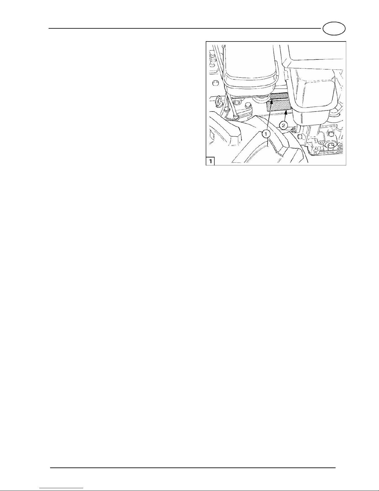
TWO-WHEEL TRACTOR IDENTIFICATION
The serial number is stamped on the engine side of
the gear box of your two-wheel tractor (see fig. 1, item
1).
ENGINE IDENTIFICATION
Refer to the engine Operation and Maintenance Man-
ual.
EC MARKING
The two-wheel tractor is marked EC in compliance with
the Directive of the European Community Council
89/392/EEC and further amendments (see fig. 1, item 2).
The summary of the EC marking related to the 1000
and 1000 Special models are indicated below.

GB
6
Test conditions:
- P.T.O.: Disengaged - machinestationary on a
concrete plane surface
Test conditions: - P.T.O.: Engaged
Sound
pressure on
operator’s ears
dB(A)
Sound
pressure on
operator’s ears
dB(A)
(Macchine
stationary
on a grass
surface)
(Macchine
stationary on a
concrete surface
with an interposed
elastic layer)
(Machine
running on a
concrete surface
with an interposed
elastic layer)
Acoustic power
dB(A)
Acoustic power
dB(A)
Acceleration
on hangrip
EN 1033 - 28662/1
m/sec2
Acceleration
on hangrip
EN 1033 - 28662/1
m/sec2
NOISE AND VIBRATIONS
TYPE OF MARKING
TWO-WHEEL TRACTOR 1000 (2+2)
Models:
(punched on the gearbox)
1000 (2+2) - 1000 Diesel (2+2)
Progressiv unit number starting from AG03838
81,5 -86 102,5 -
With SICKLE BAR MOWER cm. 117With ROTARY TILLER cm. 60
Engine:
Mass (weight):
HONDA GX 160
cm. 60
with wheels 4.00-8
with rotary tiller
Modello tipo:
N. Serie:
Mot.:
Potenza: kW/ rpm
Anno di Fabbricazione:
Massa: kg
1000 (2+2)
GX 160
4 3600
83,500
BH25X00000
MT2001-4GB
S/N reading: type of machine
year of manufacturing
000 week of production
00 progressiv n° of production
X
00
000
BH25
VALPADANA
42018 SAN MARTINO IN RIO
REGGIO EMILIA - ITALY
S.p.A.
84,5 -2,63 87,5 103,5 12,48
With SICKLE BAR MOWER cm. 117With ROTARY TILLER cm. 60
Engine:
Mass (weight):
LOMBARDINI 1 IM 359
cm. 60
with wheels 4.00-8
with rotary tiller
Modello tipo:
N. Serie:
Mot.:
Potenza: kW/ rpm
Anno di Fabbricazione:
Massa: kg
1000 (2+2)
1 IM 359
6,6 3600
94,500
BH25X00000
VALPADANA
42018 SAN MARTINO IN RIO
REGGIO EMILIA - ITALY
S.p.A.
89,5 103,5 2,89 89 107,5 12,08
With SICKLE BAR MOWER cm. 117With ROTARY TILLER cm. 60
Engine:
Mass (weight):
LOMBARDINI 15 LD 315
4.00-10
with rotary tiller cm. 60
with wheels
Modello tipo:
N. Serie:
Mot.:
Potenza: kW/ rpm
Anno di Fabbricazione:
Massa: kg
1000 Diesel (2+2)
15 LD 315
5 3600
121,500
BH25X00000
VALPADANA
42018 SAN MARTINO IN RIO
REGGIO EMILIA - ITALY
S.p.A.
<2,5
GB
93 103,6
14
89 107,5 12,08
With SICKLE BAR MOWER cm. 117With ROTARY TILLER cm. 60
Engine:
Mass (weight):
YANMAR L70
4.00-10
with rotary tiller cm. 60
with wheels
Modello tipo:
N. Serie:
Mot.:
Potenza: kW/ rpm
Anno di Fabbricazione:
Massa: kg
1000 Diesel (2+2)
L70
5,7 3600
115,500
BH25X00000
VALPADANA
42018 SAN MARTINO IN RIO
REGGIO EMILIA - ITALY
S.p.A.
100% max peak R.P.M.
6,4
-----
With SICKLE BAR MOWER cm. 117With ROTARY TILLER cm. 60
Engine:
Mass (weight):
HONDA GX 200
cm. 60
with wheels 4.00-8
with rotary tiller
Modello tipo:
N. Serie:
Mot.:
Potenza: kW/ rpm
Anno di Fabbricazione:
Massa: kg
1000 (2+2)
GX 200
4 3600
85,000
BH25X00000
VALPADANA
42018 SAN MARTINO IN RIO
REGGIO EMILIA - ITALY
S.p.A.
-
-----
With SICKLE BAR MOWER cm. 117With ROTARY TILLER cm. 60
Engine:
Mass (weight):
ROBIN EX 27
cm. 60
with wheels 4.00-8
with rotary tiller
Modello tipo:
N. Serie:
Mot.:
Potenza: kW/ rpm
Anno di Fabbricazione:
Massa: kg
1000 (2+2)
EX 27
5,9 3600
90,000
BH25X00000
VALPADANA
42018 SAN MARTINO IN RIO
REGGIO EMILIA - ITALY
S.p.A.
-

GB
7
Test conditions:
- P.T.O.: Disengaged - machinestationary on a
concrete plane surface
Test conditions: - P.T.O.: Engaged
Sound
pressure on
operator’s ears
dB(A)
Sound
pressure on
operator’s ears
dB(A)
(Macchine
stationary
on a grass
surface)
(Macchine
stationary on a
concrete surface
with an interposed
elastic layer)
(Machine
running on a
concrete surface
with an interposed
elastic layer)
Acoustic power
dB(A)
Acoustic power
dB(A)
Acceleration
on hangrip
EN 1033 - 28662/1
m/sec2
Acceleration
on hangrip
EN 1033 - 28662/1
m/sec2
NOISE AND VIBRATIONS
Models:
()
1000 (2+2) E
Progressiv unit number starting from
punched on the gearbox
AG03838
81,5 -86 102,5 12,48
With SICKLE BAR MOWER cm. 117With ROTARY TILLER cm. 50
Engine:
HONDA GC 160
4.00-8
cm. 50
Mass (weight):
with wheels
with rotary tiller
Modello tipo:
N. Serie:
Mot.:
Potenza: kW/ rpm
Anno di Fabbricazione:
Massa: kg
1000 (2+2)
GC 160
3,7 3600
78,000
BH25X00000
S/N reading: type of machine
year of manufacturing
000 week of production
00 progressiv n° of production
BH25
X
00
000
VALPADANA
42018 SAN MARTINO IN RIO
REGGIO EMILIA - ITALY
S.p.A.
<2,5
TYPE OF MARKING
TWO-WHEEL TRACTOR 1000 (2+2) E
GB

GB
8
Modello tipo:
N. Serie:
Mot.:
Potenza: kW/ rpm
Anno di Fabbricazione:
Massa: kg
1000 Special (3+2)
1IM359
6,6 3600
111,000
BH50X00000
Engine:
Mass (weight):
LOMBARDINI 1 IM 359
with wheels 4.00-10
with rotary tiller cm. 60
84,5 2,63 87,5 103,5 12,48
With SICKLE BAR MOWER cm. 117
TYPE OF MARKING
TWO-WHEEL TRACTOR 1000 (3+2)
Models: 1000 Special (3+2) - 1000 Diesel Special (3+2)
Progressiv unit number starting from
(punched on the gearbox)
AD01852
With ROTARY TILLER cm. 60
-
89,5 103,5 2,89 89 107,5 12,08
With SICKLE BAR MOWER cm. 117With ROTARY TILLER cm. 60
Engine:
LOMBARDINI 15 LD 315
cm. 60
Mass (weight):
with wheels 4.00-10
with rotary tiller
Modello tipo:
N. Serie:
Mot.:
Potenza: kW/ rpm
Anno di Fabbricazione:
Massa: kg
15 LD 315
5 3600
133,000
1000 Diesel Special (3+2)
BH50X00000
VALPADANA
42018 SAN MARTINO IN RIO
REGGIO EMILIA - ITALY
S.p.A.
VALPADANA
42018 SAN MARTINO IN RIO
REGGIO EMILIA - ITALY
S.p.A.
Test conditions: - Engine R.P.M.: 85% peak R.P.M.
- P.T.O.: Disengaged - machinestationary on a
concrete plane surface
Test conditions: - P.T.O.: Engaged
Sound
pressure on
operator’s ears
dB(A)
Sound
pressure on
operator’s ears
dB(A)
(Macchine
stationary
on a grass
surface)
(Macchine
stationary on a
concrete surface
with an interposed
elastic layer)
(Machine
running on a
concrete surface
with an interposed
elastic layer)
Acoustic power
dB(A)
Acoustic power
dB(A)
Acceleration
on hangrip
EN 1033 - 28662/1
m/sec2
Acceleration
on hangrip
EN 1033 - 28662/1
m/sec2
NOISE AND VIBRATIONS
GB
93 103,6 89 107,5 12,08
With SICKLE BAR MOWER cm. 117With ROTARY TILLER cm. 60
Engine:
YANMAR L70
cm. 60
Mass (weight):
with wheels 4.00-10
with rotary tiller
Modello tipo:
N. Serie:
Mot.:
Potenza: kW/ rpm
Anno di Fabbricazione:
Massa: kg
L70
5,7 3600
125,500
1000 Diesel Special (3+2)
BH50X00000
MT2002-4GB
S/N reading: type of machine
year of manufacturing
000 week of production
00 progressiv n° of production
X
00
000
BH50
VALPADANA
42018 SAN MARTINO IN RIO
REGGIO EMILIA - ITALY
S.p.A.
14
100% max peak R.P.M.
6,4
Modello tipo:
N. Serie:
Mot.:
Potenza: kW/ rpm
Anno di Fabbricazione:
Massa: kg
1000 Special (3+2)
GX 200
6,5 3600
111,000
BH50X00000
Engine:
Mass (weight):
HONDA GX 200
with wheels 4.00-10
with rotary tiller cm. 60
-----
With SICKLE BAR MOWER cm. 117With ROTARY TILLER cm. 60
-
VALPADANA
42018 SAN MARTINO IN RIO
REGGIO EMILIA - ITALY
S.p.A.
Modello tipo:
N. Serie:
Mot.:
Potenza: kW/ rpm
Anno di Fabbricazione:
Massa: kg
1000 Special (3+2)
EX 27
5,9 3600
116,000
BH50X00000
Engine:
Mass (weight):
ROBIN EX 27
with wheels 4.00-10
with rotary tiller cm. 60
-----
With SICKLE BAR MOWER cm. 117With ROTARY TILLER cm. 60
-
VALPADANA
42018 SAN MARTINO IN RIO
REGGIO EMILIA - ITALY
S.p.A.

GB
9
TECHNICAL SPECIFICATIONS
ENGINE
The two-wheel tractor may be fitted with the following
engines:
−HONDA GC 160; 4 stroke gasoline;
3,7 kW (5 HP); 160 cm3.
−HONDA GX 160; 4 stroke gasoline;
4 kW (5,5 HP); 163 cm3.
−HONDA GX 200; 4 stroke gasoline;
4,8 kW (6,5 HP); 198 cm3.
−ROBIN EX 27; 4 stroke gasoline;
5,9 kW (8 HP); 265 cm3.
−LOMBARDINI 1 IM 359; 4 stroke gasoline;
6,6 kW (9 HP); 349 cm3.
−LOMBARDINI 15 LD 315; 4 stroke Diesel;
5 kW (6,7 HP); 315 cm3.
−YANMAR L70; 4 stroke Diesel;
5,7 kW (7,7 HP); 296 cm3.
STARTING
Rewind start device as standard. Some models may
be fitted with electric starter upon request.
ELECTRIC STARTING (upon request)
Upon request, two-wheel tractors can be fitted with
electric starter with key control.
The 12 V battery has a capacity (40 hours) equal to
28 Ah.
CLUTCH
Multi plate dry clutch with control lever on left han-
dlebar.
SPEEDS
Speeds are engaged through a lever fitted to the col-
umn.
Models 1000 (2+2)
Two-wheels tractor configuration: 2 forward speeds
and 1 reverse speeds.
Configuration with front-mounted attachments: 2 for-
ward speeds and 2 reverse speeds.
MAXIMUM SPEED km/h
MOD. 1000 (2+2) – 1000 E (2+2)
NOTE:
Tyres
4.00-8
Models 1000 (3+2)
Two-wheel tractor configuration: 3 forward speeds
and 1 reverse speeds.
Configuration with front-mounted attachments: 2 for-
ward speeds and 2 reverse speeds.
When the machine is fitted with front-mounted at-
tachments, forward speeds become reverse speeds
and vice versa because of reversal of the direction of
motion. The maximum speed that can be attained in
the different speeds is indicated in the following table.
VELOCITA’ MASSIMA IN km/h
MOD. 1000 (3+2)
NOTA:
Pneumatici
4.00-8
TRANSMISSION
Mechanical oil bath gear box type.
DIFFERENTIAL GEAR
(Special versions)
It can be actuated by a control lever fitted to the left
handlebar (locking/unlocking).
POWER TAKE OFF (PTO)
Mounted attachments are driven via an independent,
single speed PTO engaged by a control lever on the
handlebars.
Maximum PTO speed: 943 rpm (clockwise rotation).
COUPLING OF ATTACHMENTS
Coupling of attachments to the PTO is obtained
through a quick change fitting that provides for fast
installation and removal of the attachments, and does
not require the use of bolts, nuts or spanner.
HANDLEBARS
Adjustable in height and width. Rotate handlebars
through 180° when front-mounted attachments are
used.
BRAKES (SPECIAL VERSIONS)
Mechanical controlled, independent on the two
wheels, applied by levers on the right handlebar.
WHEELS/TYRES
−Tyres with agricultural tread.
−Available sizes:
Mod. 1000 E:
4.00-8.
Mod. 1000 - 1000 Special:
4.00-8, 4.0-10 with adjustable track, 16X6.50-8.
−Inflation pressure: 1.2 bar.

GB
10
NOTE
The instructions covering track adjustment, based on
machine model and type of wheel, are given in a spe-
cific paragraph in this manual.
ACCESSORIES
The two-wheel tractor can be fitted with a wide range
of additional easy-to-fit accessories.
These are, for instance, several types of iron wheels,
watering pumps and sprayers, snow ploughs,
ploughs, trailers, water sprinkling trolleys, etc.
Refer to our catalogue for details about the various
accessories available.
MASS
Refer to the identification plate installed on the ma-
chine.
DIMENSIONS
The overall dimensions of the two-wheel tractor are
shown in fig. 2.
2
MOTOR-MOWER
TWO-WHEEL TRACTOR
590
1735
800
460 Standard
550 Special
950 ÷ 1270 550 900
1850
650 ÷ 1360
500 ÷ 1250
600
GB
11
SAFETY DEVICES
The two-wheel tractor is fitted with the following safety
devices to ensure maximum safety:
−Automatic PTO disengagement device. This is a
mechanical device that prevents shift into reverse
speed when the PTO is rotating (two-wheel tractor
configuration only).
−Engine shut-off. This is an electrical or mechanical
device (Diesel) that stops the engine as soon as
the handlebars are released.
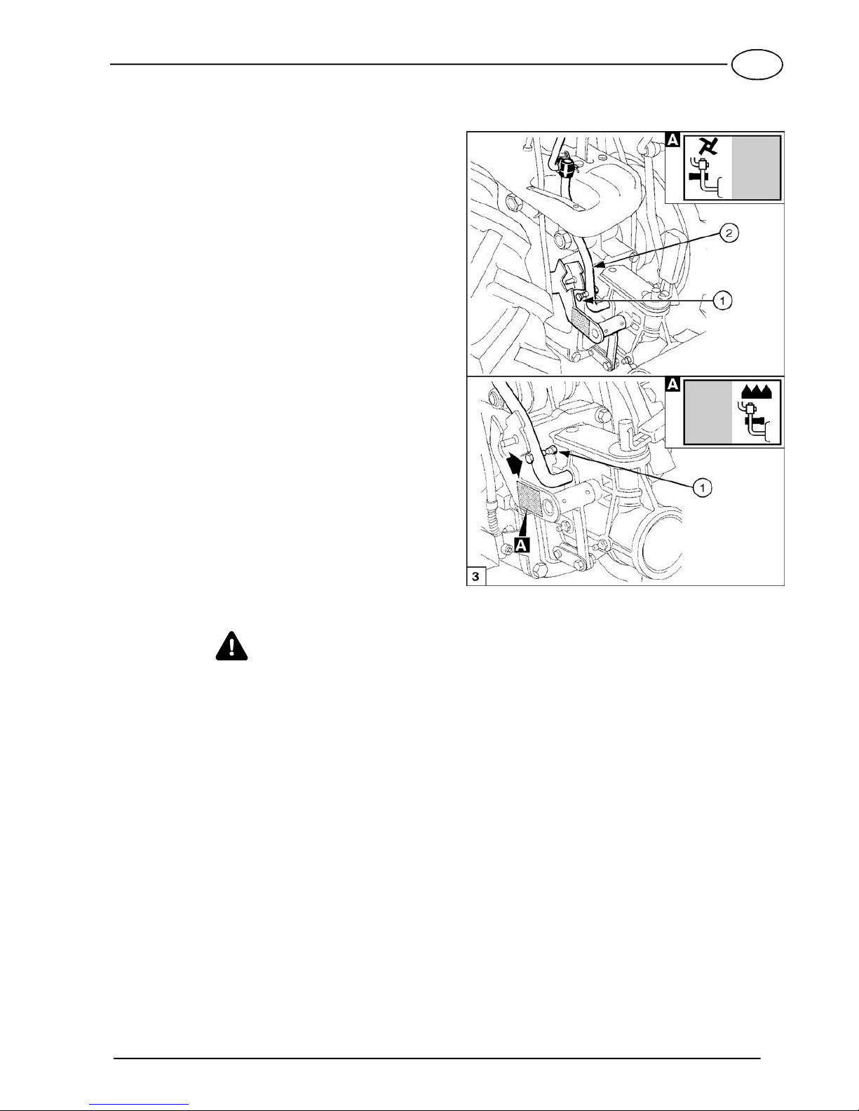
REVERSE SPEED SAFETY DEVICE
The two-wheel tractor is provided with an operator-
adjusted safety device that prevents concurrent use
of reverse speed and attachment when the rotary tiller
is fitted.
This device consists of a pin (see fig. 3, item 1) in-
stalled on the PTO control lever (2).
Disengage the PTO before removing the pin (1) and
adjusting its position.
The placard illustrated in detail A shows the position
of pin (1) as a function of the machine configuration.
−Pin pulled out: when the pin is pulled out, as
shown in the top half of fig. 3, reverse speed can
be engaged only after uncoupling the PTO (ma-
chine in two-wheel tractor version).
−Pin pushed in: when the pin is in the position illus-
trated in the bottom half of fig. 3, reverse speed
can be engaged also when the PTO is operating
(machine fitted with front-mounted attachments).
WARNING
It is mandatory to check that the safety pin is posi-
tioned as required for the selected operating configu-
ration (two-wheel tractor or front-mounted attach-
ments).
The Manufacturer waives any responsibility arising
from the incorrect use of the safety device.

GB
12
TRANSFER PRINTING -
INSTRUCTIONS AND SAFETY
Please find below the adhesive transfer printing shown
on the machine. For accident prevention purposes,
they must always be clearly readable. Should they be
damaged, it is compulsory to replace them by request-
ing the original spare part from the Manufacturer.

GB
13
TWO-WHEEL TRACTOR CONTROLS
See fig. 4.
1. Clutch lever.
2. Engine stop lever.
3. Differential lock lever.
4. PTO control lever (Note 1).
5. Handlebar vertical lock release lever.
6. Gear lever (Note 2).
7. 3rd speed preselection control lever
(versions 3+2).
8. Throttle control lever.
9. R.H. brake lever (Special versions).
10.L.H. brake lever (Special versions).
11.PTO instant adaptor.
NOTE 1: When the machine is fitted with front-
mounted attachments, this lever becomes
the gear lever.
NOTE 2: When the machine is fitted with front-
mounted attachments, this lever becomes
the PTO control lever.
OPERATING THE CONTROLS
Clutch lever
(See fig. 5)
−Lever (1) pulled up: clutch disengaged.
−Lever (1) released: clutch engaged.
Engine stop lever
(See fig. 5)
−Lever (2) pressed down: engine running.
−Lever (2) released: engine stopped.
Differential lock lever
(Special versions)
You can lock the differential when operating on diffi-
cult terrain in order to obtain maximum traction.
CAUTION
Use the differential lock while working in a straight
line only.
To lock and unlock the differential proceed as follows
(see fig. 5):
a. To lock the differential, slow down the two-wheel
tractor, and push the differential lock lever (3) for-
ward.
b. To unlock the differential, pull the clutch lever (1)
and pull the differential lock lever (3) backward.
A plate on the left handlebar (see detail A) illustrates
the use of the differential lock lever.
GB
14
Gear lever
CAUTION
When using the machine as a motor mower, the han-
dlebars must be rotated through 180°.
The gear and PTO control levers therefore inter-
change position. See page 17 for details.
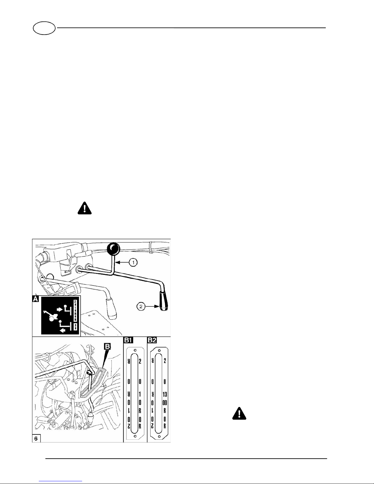
Use the gear lever as shown below (see fig. 6):
a. Turn the throttle control lever to idle position.
b. Pull up clutch lever.
c. Move the lever to the neutral position.
d. Set the speed preselection control lever (1) (only
for versions 3+2) to the fully forward position (see
the placard shown in detail A).
e. Move the gear lever (2) to the required position
(see the plate illustrated in detail B1), and release
it as soon as the gear is engaged.
f. Gradually release the clutch lever while accelerat-
ing the engine.
g. To disengage gear, pull up the clutch lever and
move gear lever (2) to the neutral position.
WARNING
A safety device does not permit reverse speed to be
engaged when the PTO is operating (rotary tilling).
3rd speed preselection control lever
(two-wheel tractor version Special 3+2)
The Special version of the two-wheel tractor is fitted
with a preselection lever for engagement of the 3rd
speed (forward speed only).
The levers are operated as follows (see fig. 6):
a. Turn the throttle control lever to idle position.
b. Pull up clutch lever.
c. Move the gear lever (2) to the neutral position “0”
which is indicated by the YELLOW marking.
d. Pull the 3rd speed preselection control lever (1) to
the fully aft position (see the placard shown in de-
tail A).
e. Move the gear lever (2) to position 3 which is indi-
cated by the YELLOW marking (see the placard
shown in detail B2), and release the lever after en-
gagement is obtained.
f. Slowly release the clutch lever while accelerating
the engine.
g. To disengage the 3rd speed, pull the clutch lever,
and return the lever (2) to position “0” which is in-
dicated by the YELLOW marking.
CAUTION
To return the two-wheel tractor to the configuration of
version 2+2, it is necesssary to move the speed pre-
selection control lever (1) back to the fully forward
position.
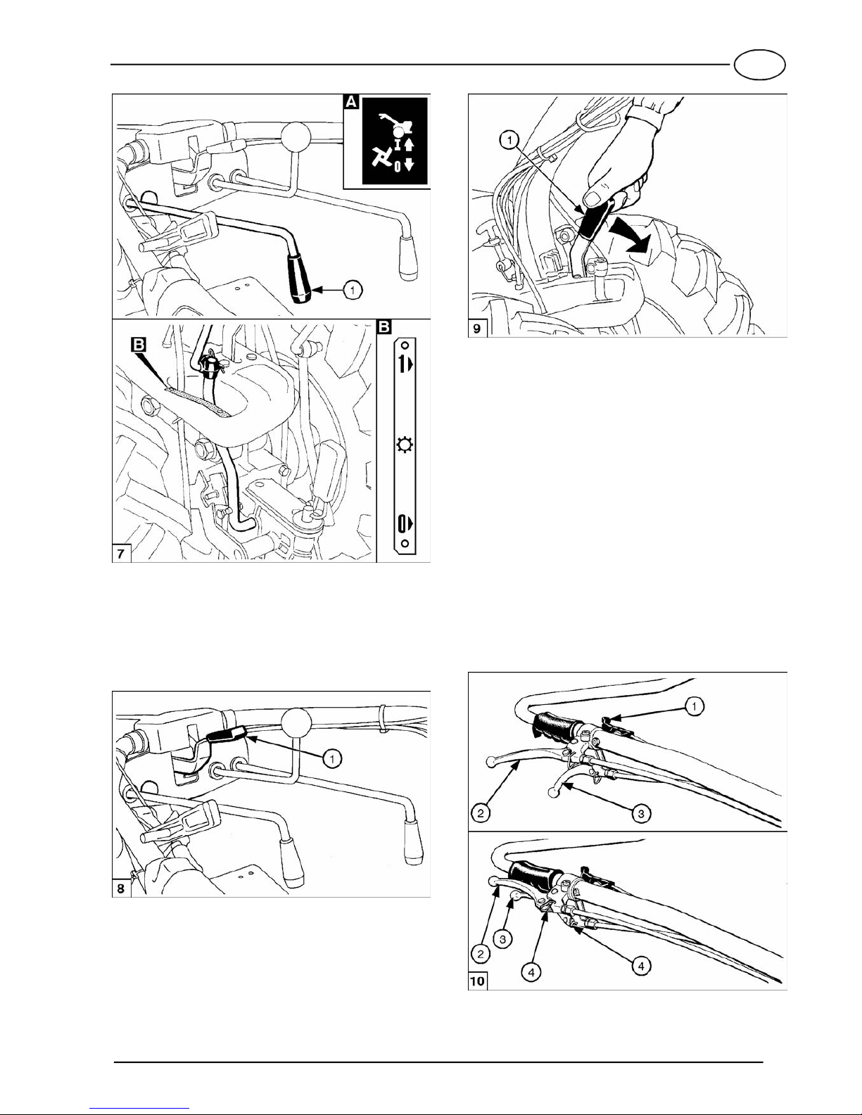
Power Take Off (PTO) control lever
(two-wheel tractor configuration)
CAUTION
When using the machine as a motor mower, the han-
dlebars must be rotated through 180°.
The gear lever and PTO control lever therefore inter-
change position. See page 17 for details.
The Power Take Off (PTO) control lever engages the
drive to the rotary tiller.
To engage and disengage drive, proceed as follows
(see fig. 7):
a. Turn throttle control lever to idle position.
b. Pull up clutch lever.
c. Pull PTO control lever (1) and release it when drive
is engaged (see plate in detail A and B).
d. Release the clutch lever while accelerating the en-
gine.
CAUTION
The clutch lever must be released slowly to prevent
damage to the drive. Do not start working with at-
tachment under load.
WARNING
A safety device prevents you from using the rotary
tiller attachment in reverse speed.
Do not use the two-wheel tractor if this safety device
is not correctly installed.
GB
15
Handlebar vertical lock release lever
(See fig. 8)
This allows the handle to be adjusted vertically to suit
driving comfort and tilling depth.
Simply push lever (1) down to release the handles.
Handlebar sideway lock release lever
(See fig. 9)
By releasing the lock, you can rotate the handlebars
to use the front-mounted attachments.
Simply push lever (1) down to release the handle-
bars.
Throttle control lever
(See fig. 10)
−Lever (1) in up position: engine at idle.
−Lever (1) in down position: max engine rpm.
Brake levers
(Special versions)
The brakes act independently on the two wheels, and
can be used separately to assist tight cornering as
well as together to slow the machine in a straight line.
Use the brakes as follows (see fig. 10):
a. To turn right, pull up the right hand brake lever (2).
b. To turn left, pull up the left hand brake lever (3).
PARKING BRAKE
(See fig. 10)
To lock the wheels for parking, pull up both brake lev-
ers (2) and (3), and engage brake locks (4).

GB
16
PTO Instant adaptor
This allows attachments to be coupled and de-
coupled quickly and easily to and from the PTO.
The lever (1) has two positions (see fig. 11):
−Locked position: pull up lever (1).
−Released position: push down lever (1).
A decal (see detail A) near the PTO instant adaptor
lever illustrates operation. See page 18 for instruc-
tions on how to fit the attachments.
CONTROLS OF FRONT-MOUNTED
ATTACHMENTS
When the machine is used with front-mounted at-
tachments, the gear and the PTO levers are reversed
with respect to when the machine is used as a two-
wheel tract. This is due to reversal of the direction of
motion. Lever (fig. 12, item 1) becomes the gear lever,
and lever (2) becomes the PTO control lever.
The symbols shown in figure 12 and applied to the
column, remind the user about the functions of the
levers.
OPERATING THE
TWO-WHEEL TRACTOR
WARNING
Before operating your two-wheel tractor, read care-
fully and commit to memory the instructions given in
the “SAFETY REGULATIONS” paragraph at the be-
ginning of this manual.
STARTING THE ENGINE
NOTE
See the engine Operation and Maintenance Manual
for all informations regarding the engine.
CAUTION
Oil bath air filter (if fitted) - When delivered new,
there is no oil in the air filter.
Before using your two-wheel tractor, add motor oil up
to the marked level.
a. Disengage all control levers before starting the
engine.
b. Gasoline engines: in order to gain access to the
refuelling cap, it is necessary to open the hood.
Unlock the turnbuckle (fig. 13, item 1), open the
hood (2), and rotate the lever (3) upward.
c. Gasoline engines: open the fuel cock.
d. Gasoline engines: if cold starting the engine, use
the choke.
e. Press down the engine stop lever (fig. 14, item 1).
f. Pull clutch lever (2) fully up.

GB
17
g. Lock the clutch lever (2) in position with locking
device (3).
h. Turn throttle control lever (4) for 1/4 turn.
i. Gasoline engines: grip the pull-rope handle and
pull firmly and quickly. When the engine starts, al-
low the rope to wind back onto the reel slowly.
Diesel engines: manually wind the rope on the
reel, and pull firmly and quickly.
j. Turn the throttle control lever (4) to idle position,
and allow the engine to warm up.
NOTE
Do not leave the clutch lever pulled up for an ex-
tended length of time after the engine has started.
This could cause damage to the clutch.
STOPPING THE ENGINE
a. Turn throttle control lever (fig. 15, item 1) to idle
position.
b. Release the engine stop lever (2).
c. Gasoline engines: if you plan not to use your
two-wheel tractor for a long time, shut off the fuel
cock.
d. Gasoline engines: if you plan not to use your
two-wheel tractor for a long time (over a week),
drain the carburettor bowl.
WARNING
The engine stop lever (2) also operates as a safety
device (emergency stop), and stops the engine as
soon as it is released.
FITTING FRONT-MOUNTED
ATTACHMENTS
Before fitting a front-mounted attachment (cutter bar
mower, rotary mower, snow thrower, etc.) you must
set the safety device in “motor mower” configuration,
remove the 3rd speed preselection control lever and
reverse the handlebars and the position of the
wheels.
NOTE
The control cables that are routed to the top part of
the gearbox are the following:
−clutch control cable;
−differential gear control cable;
−right wheel brake control cable;
−left wheel brake control cable.
Check that the position of the cables in the two-wheel
tractor version is as shown in fig. 16.
SAFETY DEVICE
Set the reverse speed safety device in the correct po-
sition as regards the direction of travel (see fig. 3).
WARNING
•Before using the machine, check that the locking
pin is in correct position
•Before using the machine in two-wheel tractor con-
figuration, you must position the locking pin as re-
quired to prevent engagement of the PTO when the
tiller is rotating, as shown in figure 3.

GB
18
REMOVAL OF 3rd SPEED
PRESELECTION CONTROL LEVER
When front-mounted attachments are used, it is nec-
essary to remove the 3rd speed preselection control
lever from the machine. To do this, proceed as follows
(see fig. 17):
a. Move the preselection control lever (1) to the fully
forward position.
b. Release the spring clip (2), and slide the terminal
of the lever (1) out of the control pin (3). Pull up-
ward.
CAUTION
The above operations cannot be carried out if the pre-
selection control lever (1) is not correctly positioned
(it is not pushed to the fully forward position) as inter-
ference with the locking pawl could result.
c. Unscrew the knob (4) from the lever (1).
d. Slide the lever (1) out of its housing on the han-
dlebar support (6).
CAUTION
The joint (5) between the lever (1) and its terminal
must not be disassembled. Keep the lever assembly
in a safe place for reuse when the machine is oper-
ated in two-wheel tractor version.
e. When the machine is used again in two-wheel
tractor version (3rd speed available), reinstall the
preselection control lever assembly (1) by carrying
out the procedure described above in a reverse
order.
REVERSING THE HANDLEBARS
Rotate the handlebars through 180° to operate the
machine in the changed direction of motion.
Proceed as follows (see fig. 18):
a. Remove pins (1) and (2) connecting the gear rod
(3) and the PTO control rod (4).
b. Push lever (5) downward, and rotate the handle-
bars sideways through 180° in clockwise direction.
c. Release lever (5), and lock the handlebars.
d. Connect again the gear (3) and PTO (4) control
rods to the corresponding control levers and se-
cure with pins (1) and (2).
NOTE
While reversing the handlebars, make sure that the
cables do not become tangled or caught.
REVERSING THE WHEELS
Every time you use a front-mounted attachment, the
wheels must be interchanged to keep the tread pat-
tern pointing in the right direction.
Simply remove each wheel from its hub and install it
on the opposite hub.
An arrow on the sidewall of the tire indicates the cor-
rect direction of rotation.
This manual suits for next models
1
Table of contents


