Troy-Bilt GTX 18 User manual

Models
13074-
GTX 18 (18 HP)
13076-GTX 20 (20 HP)
131ol-
GTX
llt>(ttDHP)
Owner/Operator
Manual
GTX
Garden
Tractor
•
Safety
•
Operation
•
Maintenance
$7.50
Form 1772567 (1/96)
Supersedes 1770645 Rev. A (2/95)

Introduction
Thank
you
for
purchasing
this
product.
We
feel
you
now
own
one
of
the
finest
pieces
of
outdoor
power
equipment
available.
All
information
in
this
manual
is
based
on
the
latest
product
information
available
at
the
time
of
printing.
This
manual
is
considered
a
permanent
part
of
the
unit
and
must
stay
with
the
unit
if
resold.
This
is
a
safety,
operation,
and
general
maintenance
manual
which
does
not
attempt
to
cover
major
repairs.
Our
equipment
is
carefully
designed,
engineered
and
manufactured
for
excellent
performance
if
properly
operated
and
maintained.
Table
of
Contents
SERVICE
INFORMATION
....
..
.
..
.....
..
.....
....
.
..
... 3
Unit
Service
and
Repair
....
..................................
3
Warranty
Service
..
...
...
...
...
...
.
..
...
...
...
...
...
.
..
..
..
......
3
Left
and
Right
Sides
...........................................
3
Engine
Serviee
.............................................
.......
3
Repair
Manual
..............
......................................
3
Replacement
Owner
Manual
...............................
3
SPARK
ARRESTER
WARNING
....................
....
. 3
IDENTIFICATION
NUMBERS
.................
~.........
3
SAFETY
................................................... 4
SAFETY
DECAL
.......................................... 9
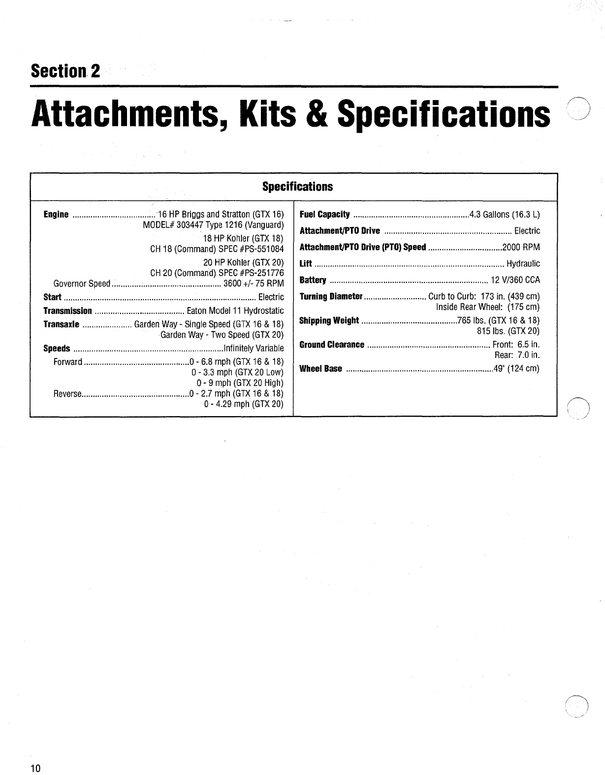
ATTACHMENTS,
KITS
AND
SPECIFICATIONS
.......
10
CONTROLS
...............................................
12
BEFORE
OPERATION
....................................
14
OPERATION
..............................................
16
Starting
Engine
...................................................
16
Throttle
Setting
...................................................
16
Stopping
Engine
.................................................
16
Interlock
System
................................................
17
Perform
Electric
Clutch
Break-in
Procedure
.......
17
Attachment/PTO
Drive
........................................
17
Hydraulic
Attachment
Lift
...................................
17
Auxiliary
Hydraulic
Connections
.........................
17
Hydrostatic
Transmission
...................................
18
Travel
Pedal
........................................................
18
?
Read
this
manual
to
familiarize
yourself
with
the
unit,
its
features,
and
operation.
The
unit
has
passed
the
rigid
safety
standards
set
by
the
Outdoor
Power
Equipment
Institute
and
an
independent
testing
laboratory.
The
unit's
warranty
statement
is
included
on
the
back
cover
of
this
manual.
Read
it
thoroughly.
Also,
please
complete
and
return
the
postage-paid
owner
registration
card
included
with
this
manual.
This
card
registers
each
unit
and
owner
at
the
factory
in
order
to
provide
bulletins
and
safety
literature.
Light
Switch
.......................................................
18
Moving
Tractor
ManHally
....................................
19
Cruise
Control
....................................................
19
Brake/Neutral
Pedal
............................................
19
LUBRICATION
AND
MAINTENANCE
...................
20
Checking
Engine
Oil
Level
..................................
20
Changing
Engine
Oil
...........................................
20
Changing
Engine
Oil
Filter
..................................
20
Engine
Air
Intake
Screen
....................................
21
Engine
Air
Cleaner
..............................................
21
Fuel
Filter
............................................................
21
Carburetor
..........................................................
22
Battery
................................................................
22
Spark
Plugs
........................................................
22
Front
Axle
Adjustment
........................................
22
Front
Wheel
Alignment
.......................................
22
Power
Steering
...................................................
22
Proper
Jack
Placement
.......................................
23
Interlock
Switches
..............................................
23
Brake
Adjustment
...............................................
23
Hydrostatic
Maintenance
and
Lubrication
..........
23
Travel
Pedal
Adjustment
.....................................
24
Hydrostatic
Neutral
Adjustment
..........................
24
Lubrication
Chart
................................................
25
;)
/
Troubleshooting
Chart
........................................
26
~
' \
Storage
...............................................................
27
;
Maintenance
Chart
.............................................
27

Service
Information
Unit
Service
and
Repair
Engine
Service
Contact
your
authorized
dealer
to
service
the
unit.
Provide
your
dealer
with
the
unit's
model/serial
number
and
the
part's
description.
Do
not
return
parts
directly
to
the
factory.
For
engine
service,
contact
your
authorized
engine
dealer.
To
locate
your
authorized
engine
dealer,
refer
to
the
"Yellow
Pages"
under
"Engines-Gasoline"
or
"Gasoline-Engines".
Provide
your
dealer
with
the
engine
model
and
serial
numbers.
Warranty
Service
The
warranty
for
the
unit
is
printed
on
the
back
cover
of
this
manual.
Warranty
service
is
available
from
your
authorized
dealer.
Left
and
Right
Sides
Left
and
right
sides
of
the
unit
are
determined
from
the
operator's
position,
facing
the
direction
of
forward
travel.
Repair
Manual
A
repair
manual
is
available
from
your
dealer.
Replacement
Owner/Operator
Manual
A
replacement
owner/operator
manual
is
available,
from
the
factory.
To
order,
call
or
write
to
the
address
on
the
back
cover
of
this
manual.
Identification
Numbers
For
prompt
service,
provide
your
authorized
dealer
with
the
identification
numbers
of
the
unit.
The
unit's
identification
numbers
are
located
on
a
decal,
beneath
the
seat,
on
the
rear
fender.
For
prompt
service,
provide
your
authorized
dealer
with
these
identification
numbers.
Fill
in
the
spaces
below
with
these
identification
numbers
for
future
reference.
Date
of
Purchase:
Transmission
Model/Serial
Number:
Unit
Serial
Number:
Engine
Model/Serial/Spec.
Numbers:
NOTE:
Model
number
of this unit is
the
first five
numbers
of
the
model/serial
number.
WARNING:
Engine
exhaust
from
this
product
contains
chemicals
known
to
the
State
of
California
to
cause
cancer,
birth
defects
or
other
reproductive
harm.
A
WARNING
OPERATORS
IN
CALIFORNIA
AND
OTHER
APPLICABLE
STATES.
Under
California
law,
and
under
the
laws
of
several
other
states,
it
is
not
lawful
to
operate
an
internal
combustion
engine
using
hydrocarbon
fuels
on
any
forest
covered,
brush
covered,
or
grass
covered
land;
or
on
land
covered
with
grain,
hay,
or
other
flammable
agricultural
crops,
without
an
engine
spark
arrester
installed
and
in
continuous
effective
working
order.
The
internal
combustion
engine
on
this
unit
burns
gasoline,
a
hydrocarbon
fuel.
Therefore,
this
unit
must
be
equipped
with
a
spark
arrester
muffler
in
continuous
effective
working
order.
The
spark
arrester
must
be
attached
to
the
engine
exhaust
system
in
such
a
manner
that
flames
or
heat
from
the
system
will
not
ignite
flammable
material.
Failure
of
the
owner/operator
of
this
unit
to
comply
with
this
regulation
is
a
misdemeanor
under
California
law,
and
may
also
be
a
violation
of
other
state
and/or
federal
regulations,
laws,
ordinances,
or
codes.
Contact
the
local
fire
marshal
or
forest
service
for
specific
information
about
which
regulations
apply
in
your
area.
3

Section
1
Safety
Important!
Safe
Operating
Practices
for
This
Unit
This
is
a safety alert symbol. It
is
used
in
this manual
and
on
decals
on
the unit to alert you to .
potential
hazards.
Whenever you
see
this symbol,
read
and
obey
the safety
message
that follows
1t.
Failure to
obey
the
safety
message
could result
in
personal injury or property damage.
Introduction
1.
Unit
is
capable
of
amputating
hands
and
feet
and
throwing
objects.
Failure
to
observe
the
following
safety
instructions
could
result
in
serious
injury
or
death.
2.
Serious
accidents
which
may
cause
injury
or
property
damage
can
occur
if
the
following
safety
guidelines
are
not
followed.
Operator
is
solely
responsible
for
accidents
or
hazards
that
occur
when
using
unit.
Preventing
accidents
is
the
responsibility
of
every
equipment
operator.
Accidents
can
be
prevented.
Be
careful
before,
during
and
immediately
after
use
of
any
powered
equipment.
The
following
general
safety
precautions
must
be
fully
understood
and
followed
during
operation.
Review
these
instructions
frequently
and
never
take
chances.
If
you
do
not
understand
any
part
of
this
manual
or
need
assistance,
contact
your
dealer
or
our
service
department.
4
Training
1.
Read,
understand
and
follow
all
instructions
in
this
manual
and
on
unit
before
starling.
A
free
replacement
manual
is
available
from
the
factory.
To
order
a
replacement
manual,
contact
the
factory
at
the
address
indicated
in
this
manual.
Provide
the
model/serial
number
of
unit
when
ordering.
2.
Read
and
understand
the
operator's
manual
provided
with
each
attachment
used
with
this
unit.
3.
Read
the
engine
operation
and
maintenance
manual
provided
with
this
unit
before
operation.
Read
and
follow
all
safety
instructions
provided
in
that
manual.
4.
Only
allow
responsible
adults,
who
are
familiar
with
the
instructions,
to
operate
the
unit.
5.
Know
the
location
and
function
of
all
controls
before
operating
unit.
Know
how
to
stop
engine
and
attachments
quickly
in
case
of
emergency.
Familiarize
yourself
with
all
safety
and
operation
decals
on
unit
and
attachments.
If
these
decals
are
damaged
or
not
legible,
clean
or
replace
them
as
needed.
Preparation
1.
Wear
proper
clothing
when
operating
unit.
Always
wear
sturdy
footwear
(preferably
steel-toed
shoes)
and
hearing
protection
during
operation.
a.
Wear
heavy
leather
gloves
whenever
working
near
or
servicing
any
cutting
edges
on
unit.
b.
Do
not
wear
loose-fitting
clothing,
jewelry,
scarves,
ties,
etc.,
which
may
get
caught
in
moving
parts.
Tie
up
or
restrain
long
hair.
c.
Do
not
operate
unit
while
barefoot.
Do
not
wear
sandals.
d.
Wear
long
trousers.
e.
Wear
hearing
protection.
2.
Do
not
operate
unit
when
tired,
ill
or
under
the
influence
of
alcohol
and/or
other
drugs.
3.
Be
prepared
for
an
emergency.
Keep
afirst
aid
kit
and
fire
extinguisher
handy.
Keep
emergency
telephone
numbers
for
ambulance,
fire,
~
hospital,
doctor
and
rescue
near
your
..
j
telephone.

Before
Operation
1.
2.
3.
4.
Before
each
use,
clear
work
area
of
objects
such
as
rocks,
toys,
wire,
etc.,
which
could
be
picked
up
and
thrown
by
mower
blades.
Keep
unit
in
safe
operating
condition.
Check
the
following
each
time
before
starting
unit:
a.
All
hardware
for
tightness
(especially
blade
mounting
hardware-check for
proper
torque
specifications
frequently
in
this
area--refer
to
maintenance
section
of
attachment
owners
manual).
b.
Brakes,
steering
and
other
major
controls
for
proper
operation.
c.
Inspect
mower
blades
for
wear
or
damage.
Broken
pieces
thrown
from
a
worn
or
damaged
blade
can
cause
serious
injury.
d.
Check
for
and
maintain
correct
tire
pressure.
Check
tires
for
cuts
or
bubbles.
Check
wheels
for
damage
or
missing
hardware.
Repair
or
replace
as
required.
e.
Check
engine
oil
level
and
add
oil
as
required.
If
oil
level
is
below
"ADD"
mark,
DO
NOT
run
engine.
Do
not
operate
unit
or
attachments
without
safety
devices
and
shields
in
place
and
operating
properly.
Only
use
attachments
which
are
approved
for
use
with
this
unit.
Contact
our
service
department
if
there
is
a
question
whether
an
attachment
is
approved
for
unit.
5.
When
using
attachments,
use
wheel
weights
(where
required)
for
extra
traction
and
proper
balance.
6.
Check
brake
function
frequently.
Adjust
and
service
as
required.
See
"Brake
Adjustment"
in
"Maintenance"
section.
7.
Unit
is
equipped
with
a
safety
interlock
system,
designed
to
shut
off
engine
when
operator
leaves
seat
while
an
attachment
is
running
or
if
parking
brake
is
not
engaged.
If
the
interlock
system
is
not
working
properly,
repair
it
before
operating
this
unit.
CORRECT
ANY
MALFUNCTION
BEFORE
USING
THIS
UNIT
OR
ATTACHMENTS!
Handling
Gasoline
1.
Use
extra
care
in
handling
gasoline
and
other
fuels.
Gasoline
and
its
vapors
are
volatile
and
dangerous.
Keep
gasoline
and
gasoline
containers
away
from
hot
engine
exhaust.
Never
allow
flame,
sparks,
smoking
materials
or
other
hot
objects
near
gasoline
or
gasoline
fumes.
2.
Wipe
up
spilled
gasoline
immediately.
Only
use
approved
gasoline
containers.
3.
Leave
two
inches
of
air
space
at
top
of
fuel
tank
to
allow
room
for
expansion.
4.
Store
gasoline
in
a
cool,
well-
ventilated
area.
Never
store
unit
or
fuel
container
inside
where
there
is
an
open
flame,
such
as
a
hot
water
heater,
furnace,
etc.
Safety
(continued)
5.
Never
remove
fuel
fill
cap,
or
add
fuel
to
fuel
tank,
if
engine
is
running
or
hot.
Always
replace
fuel
fill
cap
before
starting
engine.
6.
Never
refuel
unit
indoors.
Refuel
outdoors
in
a
well-ventilated
area.
Operation
1.
When
starting
engine:
a.
Disengage
attachmenVPTO
(Power
Take-Off)
drive.
b.
Set
parking
brake.
2.
Remain
seated
when
starting
engine
and
during
operation.
Always
operate
unit
with
feet
flat
on
running
boards.
3.
Keep
hands,
feet,
face,
hair
and
clothing
away
from
rotating
parts.
Stop
engine
before
removing
grass
catcher
or
unclogging
chute.
4.
When
operating
a
mower
deck:
a.
Mow
only
in
daylight
or
in
good
artificial
light.
b.
Never
dismount
to
make
a
cutting
height
adjustment
while
the
engine
is
running.
c.
Disengage
attachmenVPTO
drive,
shut
off
engine,
remove
ignition
key
and
wait
for
all
moving
parts
to
stop
before
unclogging
discharge
chute,
mounting
grass
catcher
or
Grass
Reduction
System
(GRS).
5.
Disengage
attachmenVPTO
drive
when
transporting
unit
to
work
area
or
when
attachments
are
not
in
use.
6.
Be
aware
of
attachment
discharge
direction
and
do
not
point
it
at
anyone.
Do
not
operate
mower
decks
without
either
the
entire
grass
catcher
or
the
guard
in
place.
5

Safety
(continued)
7.
If
you
strike
a
foreign
object,
17.
Never
leave
a
running
machine
Slope
Operation
/~
disengage
attachment/PTO
drive,
unattended.
Always
turn
off
shut
off
engine,
wait
for
all
moving
attachment/PTO
drive,
set
parking
parts
to
come
to
a
stop.
Remove
brake,
stop
engine
and
remove
key
ignition
key.
Inspect
for
and
repair
before
dismounting.
any
damage
before
operating
equipment
again.
8.
Never
carry
passengers.
Passengers
Children
interfere
with
the
safe
operation
of
•
this
unit.
Passengers
could
be
struck
by
foreign
objects
and/or
thrown
1.
Slopes
are
a
major
factor
in
loss-of-
from
unit
and
could
be
severely
control
and
tip-over
accidents
which
injured.
can
result
in
severe
injury
or
death.
All
slopes
require
extra
caution.
If
9.
Be
sure
area
is
clear
of
other
people
you
cannot
back
up
the
slope
or
if
before
mowing.
Stop
machine
if
you
feel
uneasy
on
it,
do
not
anyone
enters
the
area.
Do
not
operate
this unit
on
the
slope.
operate
unit
with
children,
pets
or
1.
Tragic
accidents
can
occur
if
the
2.
Remove
·obstacles
such
as
rocks,
tree
others
nearby.
operator
is
not
alert
to
the
presence
limbs,
etc.
10.
As
a
general
rule,
do
not
mow
in
of
children.
Children
are
often
reverse.
Disengage
power
to
mower
attracted
to
the
machine
and
the
3.
Watch
for
holes,
ruts,
or
bumps.
attachments
before
backing
up.
If
it
is
mowing
activity.
Never
assume
that
Uneven
terrain
could
overturn
the
absolutely
necessary
to
back
up:
children
will
remain
where
you
last
machine.
Tall
grass
can
hide
saw
them.
obstacles.
a.
Check
area
on
ground
directly
2.
Never
allow
children
to
operate
this
4.
Always
mow
up
and
down
the
face
of
:0
behind
unit. unit,
even
under
adult
supervision.
slopes,
never
across.
Do
not
mow
!
b.
Continue
to
observe
area
down
Local
regulations
may
restrict
near
dropoffs,
ditches
or
and
to
rear
while
backing
up.
operator
age.
Only
allow
responsible
embankments.
The
unit
could
11.
Approach
blind
corners
cautiously.
adults,
who
are
familiar
with
these
suddenly
overturn
if a
wheel
goes
12.
Always
observe
the
terrain.
Watch
for
instructions,
to
operate
this
unit.
over
the
edge
of
acliff
or
ditch,
or
if
and
avoid
obstacles.
Stay
away
from
3.
Never
carry
children
as
passengers.
an
edge
caves
in.
holes,
ditches,
soft
or
steep
Do
not
carry
ANY
passengers.
They
5.
When
using
attachments
on
slopes,
embankments
and
other
potentially
may
fall
off
and
be
seriously
injured
use
wheel
weights,
as
indicated
in
dangerous
terrain.
Tall
grass
can
hide
or
interfere
with
safe
machine
Section
2,
"Attachments
and
Kits",
obstacles.
operation.
for
extra
traction
and
correct
balance.
13.
Wet
surfaces
reduce
traction
and
4.
Keep
children
out
of
the
work
area
6.
Do
not
turn
on
slopes
unless
stability.
Always
maintain
proper
and
under
the
watchful
care
of
necessary,
and
then,
turn
off
traction.
Grip
the
steering
wheel
another
responsible
adult.
attachment
drive
and
turn
slowly
and
firmly.
5.
Be
alert
and
turn
machine
off
if
gradually
downhill.
14.
Slow
down
before
turning.
children
enter
the
area.
7.
Do
not
start
or
stop
suddenly
when
15.
Do
not
install
an
automotive-type
ball
6.
Before
and
when
backing,
look
going
up
or
down
a
slope.
Keep
all
movement
on
slopes
slow
and
hitch
on
this
unit.
When
pulling
behind
and
down
for
small
children.
gradual.
Do
not
make
sudden
loads:
7.
Use
extra
care
when
approaching
changes
in
speed
or
direction.
a.
Use
approved
hitch
points.
blind
corners,
shrubs,
trees
or
other
b.
Limit
loads
to
those
which
can
be
objects
that
may
obscure
vision.
safely
controlled.
8.
Keep
children
away
while
performing
16.
Watch
out
for
traffic
when
operating
maintenance
or
adjustments.
near
or
crossing
roadways.
6

8.
If
unit
is
unable
to
continue
moving
uphill,
disengage
attachment
drive
(PTO),
check
area
on
ground
immediately
behind
unit,
watch
area
to
rear
and
proceed
backward
slowly.
9.
Do
not
operate
unit
on
steep
slopes
where
there
is
a
risk
of
an
overturn.
Do
not
mow
slopes
with
an
incline
of
more
than
10°.
Use
the
Slope
Gauge,
included
with
your
unit,
as
an
aid
in
determining
the
incline
of
a
slope.
10.
Use
extra
care
with
grass
catchers
or
other
attachments.
These
can
change
the
stability
of
unit.
11.
Do
not
operate
unit
on
wet
grass.
Reduced
traction
could
cause
sliding.
12.
Do
not
try
to
stabilize
unit
by
putting
your
foot
to
the
ground.
13.
Do
not
park
unit
on
a
hill.
Stopping
1.
Before
leaving
operator's
position
or
before
leaving
tractor
unattended:
a.
Bring
unit
to
a
complete
stop.
b.
Disengage
attachment/PTO
drive.
c.
Lower
attachments
to
ground.
d.
Set
parking
brake.
e.
Shut
off
engine
and
remove
ignition
key.
f.
Wait
for
all
moving
parts
to
come
to
a
complete
stop.
2.
Disengage
attachment/PTO
drive
when
transporting
tractor
or
when
attachments
are
not
in
use.
.
Maintenance
A
WARNING
BEFORE
PERFORMING
ANY
MAINTENANCE
OR
ADJUSTMENTS
TO
THE
TRACTOR,
ENGINE
OR
ATTACHMENTS:
DISENGAGE
THE
ATTACHMENT/PTO
DRIVE,
SHUT
OFF
THE
ENGINE
AND
WAIT
FOR
ALL
MOVING
PARTS
TO
STOP.
SET
THE
PARKING
BRAKE
AND
ALLOW
THE
ENGINE
AND
MUFFLER
TO
COOL.
1.
Before
performing
any
service,
adjustments
or
maintenance
on
unit,
engine
or
attachments:
a.
Park
unit
on
a
firm
and
level
surface.
b.
Disengage
attachment
(PTO)
drive.
c.
Lower
attachments.
d.
Move
all
control
levers
to
"Neutral".
e.
Apply
parking
brake.
f.
Shut
off
engine.
Remove
ignition
key
and
allow
engine
to
cool.
2.
Always
wear
sturdy
footwear
(preferably
steel-toed
shoes),
long
trousers,
hearing
and
eye
protection
while
doing
any
maintenance
on
unit.
Do
not
wear
loose-fitting
clothing,
jewelry,
scarves,
ties,
etc.,
which
could
get
caught
in
moving
parts.
Tie
up
or
restrain
long
hair.
3.
Mower
blades
are
extremely
sharp.
Use
caution
when
servicing.
Wear
gloves
or
wrap
blades
in
rags.
Wear
eye
protection
when
sharpening
blades.
Safety
(continued)
4.
Keep
children
away
while
performing
maintenance
or
adjustments.
5.
Provide
safe,
adequate
light
in
your
work
area.
NEVER
USE
AN
OPEN
FLAME
FOR
ILLUMINATION!
Use
only
a
portable
safety
light
enclosed
in
a
wire
cage
for
working
inside
or
under
unit.
NOTE:
Hot
filamimts
from
a
broken
light
bulb
can
ignite
spilled
fuel
or
oil.
6.
Never
"feel"
for
hydraulic
system
leaks.
Hydraulic
fluid
could
leak
at
high
pressure
and
temperatures
and
could
penetrate
and
burn
skin.
7.
Keep
nuts
and
bolts
tight
(especially
blade
mounting
hardware-check
for
proper
torque
specifications
frequently
in
this
area--refer
to
maintenance
section
of
attachment
owners
manual).
Keep
equipment
in
good
condition.
8.
Never
tamper
with
safety
devices.
Check
their
proper
operation
regularly.
Repair
or
replace
as
necessary.
9.
Keep
machine
free
of
grass,
leaves
or
10.
other
debris
build-up.
Clean
up
oil
or
fuel
spillage.
Allow
machine
to
cool
before
storing.
Grass
catcher
components
are
subject
to
wear,
damage
and
deterioration,
which
could
expose
moving
parts
or
allow
objects
to
be
thrown.
Check
their
proper
operation
regularly.
Repair
or
replace
as
necessary
11.
Frequently
check
components
and
replace
when
necessary.
Use
only
factory-
approved
replacement
parts.
Parts
manufactured
by
others
may
present
safety
hazards
even
though
they
may
fit
on
the
unit.
12.
Replace
muffler
if
worn
or
defective.
13.
Keep
all
safety
and
operation
decals
in
place.
If
these
decals
are
damaged
or
not
legible,
clean
or
replace
them
as
needed.
Refer
to
the
parts
catalog
for
decal
description
and
location.
7

Safety
(continued)
14.
Check
brake
operation
frequently.
Engine
Adjust
and
service
as
necessary
as
indicated
in
Section
7
"Maintenance".
15.
Chock
wheels
(place
blocks
of
wood
in
front
and
behind
wheels)
when
performing
maintenance
with
the
parking
brake
off.
Securely
support
unit
if
it
must
be
raised
for
any
reason.
1
6.
Check
wheel
attachment
hardware
regularly
and
ensure
it
is
properly
secured.
17.
Do
not
attempt
to
mount
a
tire
on
a
wheel
rim
unless
you
are
experienced
in
doing
so.
Follow
proper
safety
precautions
and
use
proper
tools.
Mounting
a
wheel
improperly
could
result
in
serious
injury
or
death.
18.
Do
not
inflate
tires
above
recommended
pressures.
Use
a
clip-
on
chuck
to
inflate
tires,
with
an
extension
hose
long
enough
to
allow
you
to
stand
to
one
side
and
NOT
over
or
in
front
of
the
tire
assembly.
19.
Towing
or
pushing
unit
with
another
vehicle
will
damage
transmission.
Push
unit
by
hand
only.
20.
Use
a
heavy-duty
trailer
to
transport
unit.
Lower
attachments
to
trailer
bed.
Set
parking
brake.
Fasten
unit
securely
to
trailer
with
straps,
chains
or
cables.
Unit
must
be
secured
to
trailer
facing
forward.
21.
Use
extra
care
when
loading
or
unloading
the
machine
into
a
trailer
or
truck.
22.
Do
not
use
food
or
beverage
containers
to
store
waste
materials.
Using
such
containers
could
result
in
accidental
poisoning.
8
1.
Read
the
provided
engine
operation
and
maintenance
manual
completely
before
operation.
Read
and
follow
all
safety
instructions
provided
in
that
manual.
2.
3.
4.
5.
6.
BEFORE
SERVICING
ENGINE:
Disconnect
spark
plug
wire
and
keep
it
from
touching
spark
plug.
Keep
engine
free
of
grass,
leaves,
oil
and
grease.
Engine
exhaust
is
extremely
hot.
Keep
grass,
oil,
fuel
and
other
combustible
materials
far
away
from
engine
exhaust.
Do
not
change
engine
governor
setting.
Over-revving
may
damage
engine
and
will
void
warranty.
Never
run
an
internal
combustion
engine
inside
a
closed
area.
Engine
exhaust
contains
carbon
monoxide
gas,
a
deadly
poison.
Carbon
monoxide
is
odorless,
colorless
and
tasteless.
Do
not
operate
unit
near
buildings,
windows
or
air
conditioners.
If
engine
is
run
in
a
garage,
open
all
doors
and
allow
for
adequate
ventilation.
Battery
A
DANGER
BATTERIES
PRODUCE
EXPLOSIVE
GASSES.
KEEP
OPEN
FLAMES
AND
SPARKS
AWAY.
DO
NOT
SET
TOOLS
ACROSS
TERMINALS.
BATTERY
ELECTROLYTE
CAN
CAUSE
SEVERE
BURNS.
EYE
CONTACT
CAN
CAUSE
BLINDNESS.
ALWAYS
WEAR
EYE
PROTECTION
AND
RUBBER
GLOVES
WHEN
WORKING
NEAR
THE
BATTERY.
NEVER
WEAR
JEWELRY.
IF
ELECTROLYTE
CONTACTS
SKIN
OR
EYES,
RINSE
IMMEDIATELY
WITH
WATER
FOR
AT
LEAST
15
MINUTES.
CALL
PHYSICIAN
IMMEDIATELY.
1.
BEFORE
WORKING
WITH
ELECTRICAL
WIRES
OR
COMPONENTS:
Disconnect
the
battery
ground
(negative)
cable
first.
Disconnect
the
positive
cable
second.
The
battery
ground
(-)
cable
must
be
disconnected
first
and
reconnected
last.
2.
Before
attempting
to
charge
battery,
understand
and
follow
correct
procedure
or
bring
battery
to
a
factory-authorized
dealer
for
charging.
Do
not
charge
a
frozen
battery.
3.
Battery
electrolyte
can
cause
severe
burns.
Eye
contact
can
cause
blindness.
Always
wear
approved
safety
goggles
when
working
around
the
battery.

4.
If
electrolyte
contacts
skin
or
eyes:
a.
Flush
affected
area
with
water.
b.
Apply
baking
soda
to
neutralize
acid.
c.
Flush
eyes
with
water
for
10-15
minutes.
d.
Call
a
physician
immediately.
5.
If
electrolyte
is
swallowed:
a.
Drink
large
amounts
of
water
or
milk.
b.
Follow
by
drinking
milk
of
magnesia,
beaten
eggs
or
vegetable
oil.
c.
Call
a
physician
immediately.
6.
Electric
storage
batteries
give
off
highly
explosive
hydrogen
gas
while
charging
and
continue
to
do
so
for
some
time
after
receiving
a
steady
charge.
Do
not,
under
any
circumstances,
allow
an
electric
spark
or
an
open
flame
near
the
battery.
Do
not
lay
tools
across
the
battery
terminals
as
this
may
result
in
a
spark
or
a
short
circuit
which
may
cause
an
explosion.
Storage
1.
Do
not
store
unit
inside
a
building
where
fumes
from
fuel
in
fuel
tank
may
reach
an
open
flame
or
spark.
Allow
unit
to
cool
before
moving
it
inside
an
enclosure.
Use
a
gasoline
storage
stabilizer
when
storing
unit.
2.
Keep
unit
and
fuel
supplies
securely
locked
away
to
help
prevent
access
by
children.
3.
Remove
ignition
key.
4.
Disconnect
battery
cables
or
remove
battery
if
unit
is
to
be
stored
for
an
extended
period.
Remove
negative
(ground)
cable
first.
Re-connect
negative(-)
cable
last.
5.
Fully
charge
battery
before
storage.
Store
battery
in
a
cool,
dry
place,
out
of
reach
of
children.
Safety
Decal
Read
and
understand
the
instructions
and
safety
information
on
decals
placed
on
the
unit.
Keep
safety
and
instruction
decals
clean,
legible,
and
intact.
If
the
decals
are
worn
or
illegible,
order
replacements
and
place
them
on
the
unit.
Refer
to
the
accompanying
parts
catalog
for
the
location
and
part
numbers
of
additional
decals.
NOTE:
MAINTENANCE
DECAL
IS
UNDER
HOOD.
Safety
(continued)
9

Section2
Attachments,
Kits
&
Specifications
10
Specifications
.·
Engine
.....................................
16
HP
Briggs
and
Stratton
(GTX
16)
MODEL#
303447
Type
1216
(Vanguard)
18
HP
Kohler
(GTX
18)
CH
18
(Command)
SPEC
#PS-551
084
20
HP
Kohler
(GTX
20)
CH
20
(Command)
SPEC
#PS-251776
Governor
Speed
.................................................
3600
+1-
75
RPM
Start
......................................................................................
Electric
Transmission
........................................
Eaton
Model11
Hydrostatic
Transaxle
......................
Garden
Way-
Single
Speed
(GTX
16
&
18)
Garden
Way-
Two
Speed
(GTX
20)
Speeds
...................................................................
Infinitely
Variable
Forward
...............................................0-
6.8
mph
(GTX
16
&
18)
0-
3.3
mph
(GTX
20
Low)
0-
9
mph
(GTX
20
High)
Reverse
................................................
o-
2.7
mph
(GTX
16
&
18)
0-
4.29
mph
(GTX
20)
Fuel
Capacity
...................................................
.4.3
Gallons
(16.3
L)
Attachment/PTO
Drive
.........................................................
Electric
Attachment/PTO
Drive
(PTO)
Speed
.................................
2000
RPM
Lift
.....................................................................................
Hydraulic
Battery
.......................................................................
12
V/360
CCA
Turning
Diameter
............................
Curb
to
Curb:
173
in.
(
439
em)
Inside
Rear
Wheel:
(175
em)
Shipping
Weight
...........................................
765
lbs.
(GTX
16
&
18)
815
lbs.
(GTX
20)
Ground
Clearance
.......................................................
Front:
6.5
in.
Rear:
7.0
in.
Wheel
Base
..................................................................
49"
(124
em)
:,~
. I
/

AHachment,
Kits
and
Specifications
(continued)
Below
is
a
list
of
attachments
and
kits
available
for
this
tractor.
The
information
below
is
the
most
current,
available
at
the
time
this
manual
was
printed.
Check
with
your
nearest
authorized
dealer
for
current
information.
Number
Description
14025
42"
Side
Discharge
Mower
14026
48"
Side
Discharge
Mower
14030
48"
Rear
Discharge
Mower
14061
60"
Side
Discharge
Mower
(13076
only}
14032
Grass
Reduction
System
(42"
and
48"
mowers)
14058
Power
Packer
Plus
(Grass
Collector)
14070
Grass
Collection
Cart
14069
2-Bag
Grass
Collector
(requires
14058)
14065
33'
Tiller
1767196
8"
Hood
and
Tine
Extension
(for
14065)
14071
Sleeve
Hitch
14072
3-Point
Hitch
14073
Weight
Carrier
1319
Carrier
Weights
14066
Front
End
Loader
(requires
14073
and
1319)
(13076
only)
14075
Cab
14091
Front
Wheel
Weights
14090
Rear
Wheel
Weights
(50
lb.)
16219
Tire
Chains
(23"
Turf)
14067
Push
Arm
Kit
14074
Agricultural
Wheel
and
Tire
Kit
1767510
Arm
Rest
Kit
14068
54"
Snow
Blade
(requires
14067)
1767251
Mechanical
Angling
Kit
for
14068
(requires
14067)
14064
Hydraulic
Angling
Blades
(13076
only)
14062
42"
Snow
Thrower
(requires
14067)
14063
46"
Snow
Thrower
(requires
14067)
14076
Dump
Cart
14077
Storage
Cover
1766549
Male
Quick
Hitch
11

Section
3
Controls
Attachment
lift
Lever(G)
Auxilliary
Hydraulic
Lever
(Model13076
Only)
(f)
"
Light
Switch
(E)
Cruise
Control
Switch
(Models
13074
&
13076)
(D)
Brake/Neutral
Pedal
(B)
'
Fig.
3·1
12
p
fuel
Gauge
(Models
13074
&
13076)
(J)
0 R
'S
I
Ignition/Starter
Switch
(N)
PTO/Atlachment
Drive
Switch
(K)
Throttle
(l)
~
Travel
Pedal
(M)

Controls
(continued)
Identification
and
Function
of
Controls
and
Features
Before
operating
this
tractor,
become
familiar
with
the
function
and
location
of
each
control.
This
will
help
ensure
proper,
safe
and
efficient
operation.
See
the
"Operation"
section
for
instructions.
A.
Parking
Brake
Lever
J.
Fuel
Gauge
(13074
&
13076)
R.
Battery
Light
Locks
brake.
Set
parking
brake
when
Indicates
the
amount
of
fuel
in
the
When
lit,
indicates
low
battery
unit
is
not
in
use.
See
page
19
for
fuel
tank.
voltage.
operating
instructions.
K.
Attachment/PTO
Drive
Switch
s.
AttachmentiPTO
Drive
Light
B.
Brake
I
Neutral
Pedal
Engages
and
disengages
power
to
When
lit,
indicates
attachment/PTO
Stops
forward
or
reverse
movement
attachments.
drive
is
activated.
of
the
tractor.
See
page
19.
L.
Throttle
T.
Two-Speed
Transmission
c.
Choke
Lever
Controls
engine
speed.
Always
Lever
(Model
13076)
When
activated,
the
choke
restricts
operate
engine
at
full
throttle
iP
Lever
is
located
under
seat,
on
the
amount
of
air
mixing
with
fuel.
when
operating
attachments.
See
left
side.
Shifts
transmission
into
low
Activate
choke
when
starting
a
cold
page
16
for
instructions.
range
or
high
range.
See
engine.
Once
engine
is
started,
move
"Hydrostatic
Transmission"
on
page
lever
slowly
to
"OFF".
See
"Starting
M.
Travel
Pedal
18.
Engine"
on
page
16
for
instructions.
Controls
forward
and
rearward
movement
of
tractor.
See
page
18.
z.
Seat
Adjustment
Lever
D.
Cruise
Control
Switch
(13074
&
13076)
(13074
&
13076)
N.
Ignition
1
Starter
Switch
Locks
and
releases
seat
for
The
cruise
control
allows
the
Starts
engine.
See
page
16
for
adjustment.
Lift
lever
to
slide
seat
operator
to
maintain
a
constant
drive
engine
starting
instructions.
forward
or
backward.
See
page
19.
speed
without
contacting
the
travel
pedal.
When
activated,
the
cruise
0.
Cruise
Control
Light
control
sets
the
travel
pedal
at
the
desired
position.
See
page
19
for
(1307
4 &
13076)
instructions.
Indicates
when
cruise
control
is
on.
E.
Light
Switch
P.
Oil
Pressure
Light
Activates
headlights.
(1307
4 &
13076)
F.
Auxiliary
Hydraulic
Lever
IF
LIGHT
IS
ON,
STOP
ENGINE
IMMEDIATELY.
When
lit,
indicates
a
(Model
13076)
lack
of
oil
pressure
in
the
engine.
Activates
the
auxiliary
hydraulics.
Engine
damage
may
result.
Service
See
page
17
for
instructions.
before
re-starting.
G.
Attachment
Lift
Lever
Q.
Start
Light
Controls
the
hydraulic
attachment
lift.
Indicates
when
ignition
switch
is
in
See
page
17.
the
start
position
and
safety
start
interlock
switches
are
not
activated.
H.
Hour
Meter
Registers
hours
of
tractor
use.
13

Section
5
Before
Operation
A
DANGER
BEFORE
OPERATION,
READ
AND
UNDERSTAND
ALL
CONTROL,
OPERATING,
AND
SAFETY
INSTRUCTIONS
IN
THIS
MANUAL.
READ
ALL
MATERIAL
PROVIDED
WITH
ANY
ATTACHMENTS
USED
WITH
THE
UNIT.
READ
AND
FOLLOW
ALL
INSTRUCTIONS
ON
THE
DECALS
ON
THE
UNIT
AND
ATTACHMENTS.
A
DANGER
BEFORE
CLEANING,
PERFORMING
ANY
MAINTENANCE,
ADJUSTING,
CHECKING
OR
ADDING
FLUIDS
TO
THIS
UNIT,
SHUT
THE
ENGINE
OFF
AND
WAIT
FOR
ALL
MOVING
PARTS
TO
STOP.
14
Before
starting
the
engine,
perform
the
following
steps:
1.
Check
Engine
Oil
Level
Refer
to
your
specific
model
in
Figure
5-1.
Remove
dipstick
(A,
Fig.
5-1).
Wipe
oil
from
dipstick
with
a
clean
cloth.
Insert
dipstick
back
into
place.
Remove
dipstick
and
check
oil
level.
Keep
level
between
the
("F"
Full)
and
("L"
Add)
marks
on
the
dipstick.
If
level
is
low,
fill
engine
crankcase
through
fill
opening
(B).
Capacity w/
filter-
See
accompanying
engine
manual.
A
DANGER
DO
NOT
REFUEL
TRACTOR
INDOORS
OR
WHILE
ENGINE
IS
RUNNING
OR
HOT.
KEEP
SMOKING
MATERIALS,
SPARKS
AND
FLAMES
AWAY
FROM
FUEL
TANK
AND
FUEL
CONTAINER.
2.
Fill
Fuel
Tank
Fill
fuel
tank
with
clean,
unleaded
gasoline
with
an
octane
rating
of
87
or
higher.
Filler
neck
is
at
the
rear
of
tractor.
Leave
about
two
inches
of
room
at
the
filler
neck
for
expansion.
Do
not mix oil with gasoline!
Make
sure
the
vent
hole
in
fuel
tank
cap
is
not
plugged.
3.
Check
Engine
Flywheel
Screen
STOP
ENGINE
BEFORE
CLEANING
FLYWHEEL!
Check
engine
flywheel
screen
(C,
Fig.
5-1)
for
debris.
Clean
regularly.
/~
. )

.-···
..
_
.....
-----
n
'/.
....
_
_./
·-
...
····---
...
/
.................
r···'·······················=:·>\:····················\
'-··············
··
...
__
\:···
··································
·---...
...
·.
....
.....
\
\
...
·.
\--
..
::::·:·
................................
.
-~---··:····························
•
..-
Models
Fig.
5-2
....
·13074
& 13076
Loosen
adjustment
knobs
(ZZ),
slide
seal
forward
or
backward.
zz
'
_
..
··
Fig.
5-3
··
Model13101
4.
Visually
Check
Check
for
and
repair
loose
or
missing
screws,
nuts,
and
damaged
parts.
5.
Check
Battery
If
cables
are
corroded,
clean
them.
See
"Battery",
page
22.
Before
Operation
(continued)
Auxilliary
Hydraulic
Lever
(Model13076
Only)
(L)
Attachment
Lift
Lever
(K)
' I
Light
Switch
(E)
Choke
Lever
(G)
Fig.
5-4
A
DANGER
BATTERIES
PRODUCE
EXPLOSIVE
GASSES.
KEEP
OPEN
FLAMES
AND
SPARKS
AWAY.
DO
NOT
SET
TOOLS
ACROSS
TERMINALS.
BATTERY
ELECTROLYTE
CAN
CAUSE
SEVERE
BURNS.
EYE
CONTACT
CAN
CAUSE
BLINDNESS.
ALWAYS
WEAR
EYE
PROTECTION
AND
RUBBER
GLOVES
WHEN
WORKING
NEAR
BATTERY.
NEVER
WEAR
JEWELRY.
IF
ELECTROLYTE
CONTACTS
SKIN
OR
EYES,
RINSE
IMMEDIATELY
WITH
WATER
FOR
AT
LEAST
15
MINUTES.
CALL
PHYSICIAN
IMMEDIATELY.
.
;'
Parking
Brake
Lever
(N)
6.
Check
Tire
Pressure
Front
-
12
to
14
PSI
(82
to
96
kPa)
Rear
- 8
to
10
PSI
(55
to
68
kPa)
7.
Adjust
Seat
Models
13074
&13076-
To
adjust
seat,
lift
lever
(Z,
Fig.
5-2)
and
slide
seat
forward
or
backward.
Release
lever.
Model13101
-To
adjust
seat,loosen
adustment
knobs
(ZZ,
Fig.
5-3)
and
slide
seat
forward
or
backward.
Tighten
adjustment
knobs.
8.
Perform
Electric
Clutch
Break-in
Procedure
Perform
this
step
before
initial
use
and
after
extended
storage.Before
operating
unit,
start
engine
as
instructed
on
page
16.
With
the
engine
running
at
idle
speed,
engage
and
disengage
attachment/PTa
drive
switch
(X,
Fig.
5-4)
10
to
15
times.
15

Section
6
Operation
Auxilliary
Hydraulic
Lever
(Model13076
Only)
(L)
Attachment
Lift
Lever
(K)
" I
Light
Switch
{E)
Choke
Lever
(G)
Fig.
6-1
Starting
Engine
1.
Move
the
attachment/PTa
drive
switch
(X,
Fig
6-1)
to
"OFF".
The
starter
will
not
activate
unless
this
switch
is
off.
2.
Press
brake/neutral
pedal
(F)
down.
3.
Move
choke
lever
(G)
up.
Move
the
throttle
(J)
up
halfway.
NOTE:
AFTER
ENGINE
HAS
WARMED
UP,
OPERATE
ENGINE
AT
i!P
(FULL
THROTTLE).
4.
Insert
ignition
key
into
ignition/starter
switch
(H).
Turn
key
clockwise
to
start
engine.
Release
key
when
engine
starts.
16
;'
Ignition/Starter
Switch
(H)
Parking
Brake
Lever
(N)
False
Start:
If
engine
speeds
up
enough
to
disengage
starter
but
fails
to
continue
running,
allow
all
moving
parts
to
stop
completely
before
engaging
starter
again.
Limit
cranking
to
less
than
10
seconds.
If
engine
has
been
cranked
for
10
seconds,
allow
the
starter
to
cool
for
at
least
one
minute
before
re-
cranking.
Over
heating
may
damage
starter.
A
WARNING
IN
CASE
OF
A
FALSE
START,
ALLOW
ENGINE
TO
STOP
COMPLETELY
BEFORE
RE-STARTING.
FAILURE
TO
COMPLY
MAY
DAMAGE
STARTER.
5.
When
engine
starts,
move
choke
lever
(G)
down
halfway
(to
half
choke).
Gradually,
move
choke
lever
down
(to
choke
off)
as
the
engine
warms
up.
NOTE:
DO
NOT
RUN
ENGINE
WITH
CHOKE
ON
FOR
PROLONGED
PERIODS.
ENGINE
WILL
RUN
POORLY
(OVER-RICH
FUEL
MIXTURE)
IF
OVER-CHOKED.
6.
Move
throttle
(J)
up
to
iP
(fast).
Run
the
engine
at
full
throttle
(fast)
for
maximum
engine
efficiency.
Do
not
drive
the
tractor
immediately
after
start
up.
Allow
the
engine
to
run
for a
few
minutes.
This
allows
the
transmission
oil
to
warm
up.
7.
Perform
the
electric
clutch
break
in
procedure
as
instructed
on
page
17.
Throttle
Setting
ALWAYS
OPERATE
WITH
THE
ENGINE
AT
FULL
THROTTLE
(FAST).
While
operating
under
heavy
load
conditions,
listen
to
the
engine
RPM.
If
the
engine
begins
to
slow
down,
do
not
advance
the
travel
pedal.
Let
up
on
the
travel
pedal.
This
will
decrease
the
ground
speed
and
increase
the
engine
speed.
Stopping
Engine
1.
Turn
attachment/PTa
drive
switch
(X,
Fig.
6-1)
to
"OFF".
2.
Move
throttle
(J)
down
to
.-(Slow).
Lock
brake/neutral
pedal
(F,
Fig.
6-1
and
6-5)
down
by
pulling
parking
brake
lever
(N)
to
the
rear.
(See
Fig.
6-5,
page
19.)
3.
Idle
engine
for
at
least
30
seconds
to
allow
engine
to
cool.
4.
Turn
ignition/starter
switch
(H)
to
off.
Remove
ignition
key.

Interlock
System
Leaving
the
seat
while
the
attachment/PTO
drive
switch
(X)
is
on
or
while
the
brake
is
off will
stop
the
engine.
A
WARNING
DO
NOT
OPERATE
THE
UNIT
IF
THE
INTERLOCK
SYSTEM
DOES
NOT
FUNCTION
PROPERLY.
Interlock
System
Test
Procedure:
With
the
engine
running,
stop
tractor
on
a
level
surface,
raise
yourself
off
the
seat.
Engine
should
stop.
Engage
brake
and
turn
the
attachment/PTO
drive
switch
(X)
to
"ON".
Raise
yourself
off
the
seat.
Engine
should
stop.
If
the
engine
does
not
stop
in
both
instances,
do
not
operate
the
unit.
Have
the
interlock
repaired.
Perform
Electric
Clutch
Break-in
Procedure
Start
the
engine
as
instructed
on
page
16.
With
the
engine
running
at
full
speed,
(fast)
engage
and
disengage
attachment/PTO
drive
switch
(E,
Fig.
6-1)
10
to
15
times.
Perform
this
step
before
initial
use
and
after
extended
storage.
AHachment/PTO
Drive
To
engage
the
attachment/PTO
drive,
move
attachment/PTO
drive
switch
(X)
to
"ON".
Hydraulic
Attachment
Lift
Pull
attachment
lift
lever
(K,
Fig.
6-1)
back
to
lift
attachment.
Push
lever
forward~to
lower
attachment.
When
lever
is
released,
it
will
return
to
neutral,
except
when
pushed
fully
forward
to
"FLOAT"
position.
Use
the
"FLOAT"
position
to
allow
the
attachment
to
follow
ground
contours.
Auxiliary
Hydraulic
Lever
(20
H.P.
Units):
Pull
auxiliary
hydraulic
lever
(L)
back
to
activate
auxiliary
hydraulic
attachment.
Push
lever
forward
to
reverse
direction.
·Operation
(continued)
AUXILIARY
HYDRAULIC
CONNECTIONS
(MODEL
13076
ONLY)
····----
····;,
··----------~~~~1;;),:
(:\\
~lif;:;::)
··-.,~----·
1.
Push
coupling
(Q)
back.
2.
Install
hydraulic
hose
end.
Fig.
6·2
3.
Release
coupling.
.4\
WARNING
BEFORE
USING
HYDRAULIC
LEVERS,
MAKE
SURE
THE
ATTACHMENT
IS
COMPLETELY
HOOKED
UP.
MOVE
ATTACHMENT
THROUGH
THE
COMPLETE
LIFT
RANGE
SLOWLY
TO
MAKE
SURE
THERE
IS
NO
INTERFERENCE.
MAKE
ADJUSTMENTS
IF
NECESSARY.
Auxiliary
Hydraulic
Connections
(Model13076
Only)
Connections
for
auxiliary
hydraulics
(see
Fig.
6-2)
are
on
the
front,
right-side
of
the
frame.
To
use
these
connections,
remove
rubber
plugs.
Clean
all
dirt
and
debris
from
around
connections.
Push
coupling
(Q)
back.
Insert
hydraulic
hose
end.
When
auxiliary
connections
are
not
in
use,
secure
the
rubber
plugs
over
the
connections
to
prevent
debris
from
entering
the
hydraulic
system.
KEEP
HYDRAULIC
CONNECTIONS
CLEAN.
Dirty
hydraulic
connections
can
contaminate
the
hydraulic
fluid
and
damage
hydraulic
components.
A
WARNING
DIRTY
HYDRAULIC
CONNECTIONS
CAN
CONTAMINATE
THE
HYDRAULIC
FLUID
AND
DAMAGE
HYDRAULIC
COMPONENTS.
KEEP
RUBBER
PLUGS
IN
PLACE.
NEVER
USE
HANDS
TO
FEEL
FOR
HYDRAULIC
LEAKS.
HOT
HYDRAULIC
FLUID
LEAKING
AT
HIGH
PRESSURE
COULD
PENETRATE
SKIN.
USE
ONLY
TROY·BILT®
APPROVED
ATTACHMENTS.
Other
attachments
could
damage
the
hydraulic
system
and
void
the
warranty.
INSPECT
ALL
HYDRAULIC
COMPONENTS
FOR
HIGH
PRESSURE
LEAKS
BEFORE
TESTING
OR
REPAIRING.
Never
"feel"
for
leaks.
Oil
leaking
at
high
pressure
could
penetrate
skin.
Operating
temperatures
of
hydraulic
fluids
are
extremely
high.
17

Operation
(continued)
Auxilliary
Hydraulic
Lever
(Model13076
Only)
(L)
Attachment
Lift
Fig.
6·3
18
Light
Switch
(E)
.......
Choke
Lever
(G)
Lever(K)
I
Parking
Brake
Lever
(N)
···········
········
··y·····
Two-Speed
Transmission
Lever
(Model13076
Only)
,.......
p
...
···
...
····
..
.....
tl.,:······'.(;~!;;;:;;;;:::::::,
__
)
....
··~_?
I \
t························-~::::::::::::::::::_;./':>:::-:·.·.:······:::::::::::::::I.::··.·.::
..........
:·.
:::
.............•.........................•
//
__
;
...........
,,/················
·········
...
\ ·
..
·······································:::::::·
\.
··
............
·····
..
/
.·
·...
.
...
···
········-···
Fig.
6-4
Hydrostatic
Transmission
For
maximum
performance
when
using
attachments,
operate
engine
at
iP
,
full
throttle
(FAST).
Control
ground
speed
with
the
travel
pedal
(M)
.
The
hydrostatic
transmission
provides
the
operator
with
an
infinite
choice
of
travel
speeds.
Avoid
fast
travel
speeds
when
using
attachments.
Operate
at
slower
travel
speeds
when
snowthrowing,
mowing
and
tilling.
2-Speed
Models
(Model13076
Only):
Stop
tractor
when
shifting.
Change
speeds
with
the
transmission
lever
(P,
Fig.
6-4).
Use
"HIGH"
range
(0-9
mph)
for
transport
and
mowing.
Use
"LOW"
range
(0-3.3
mph)
for
heavy
load
conditions
such
as
tilling,
snowthrowing,
plowing
or
using
the
front
end
loader.
Travel
Pedal
The
travel
pedal
controls
forward
and
rearward
movement
of
tractor.
The
hydrostatic
transmission
gives
the
operator
an
infinite
choice
of
travel
speeds.
Press
travel
pedal
(M,
Fig.
6-3)
at
the
top
(with
toe)
to
move
forward.
Press
pedal
at
the
bottom
(with
heel)
to
move
in
reverse.
To
stop
or
slow
down
when
moving
forward:
Press
pedal
at
bottom
(with
heel).
To
stop
or
slow
down
when
in
reverse:
Press
pedal
at
top
(with
toe).
Light
Switch
To
activate
lights,
turn
light
switch
(E)
to
on.

Moving
Tractor
Manually
DO
NOT
TOW
OR
PUSH
THIS
TRACTOR
WITH
ANOTHER
VEHICLE
OR
RISK
DAMAGING
THE
DRIVE
SYSTEM.
When
pushing
the
tractor,
push
it
slowly
to
prevent
a
temporary
lock-up
of
rear
wheels.
2-Speed
Models
(20
H.P.
Units):
Stop
tractor
when
shifting.
Shift
transmission
lever
(P,
Fig.
6-4)
to
neutral.
A
WARNING
NEVER
PUSH
THIS
TRACTOR
WITH
ANOTHER
VEHICLE.
DRIVE
SYSTEM
DAMAGE
MAY
RESULT.
Cruise
Control
Cruise
control
allows
the
operator
to
maintain
a
constant
drive
speed
without
contacting
the
travel
pedal.
When
activated,
the
cruise
control
sets
the
travel
pedal
to
the
desired
position.
TO
SET:
When
tractor
is
moving
at
a
desired
speed,
press
the
cruise
control
switch
(0,
Fig.
6-3)
to
"RESET"
to
activate
cruise
control.
This
sets
the
travel
pedal.
TO
STOP:
Press
brake
pedal
(F)
or
turn
the
the
cruise
control
switch
(0)
off.
TO
RESET:
To
re-activate
cruise
control
press
"RESET".
'
Engage
pedal
(F)
before
pulling
lever
(N).
Unlock
Parking
Brake
Fig.
6-5
Parking
Brake
Brake
I
Neutral
Pedal
Parking
Brake
Lever
Press
brake/neutral
pedal
(F,
Fig.
6-3
and
6-5)
to
apply
brake
and
when
starting
engine.
To
lock
brake
(when
parked),
press
brake/neutral
pedal
and
pull
parking
brake
lever
(N)
to
the
rear,
locking
brake/neutral
pedal
down.
Operation
(continued)
19

Section
7
Lubrication
and
Maintenance
A
WARNING
BEFORE
PERFORMING
ANY
MAINTENANCE
OR
ADJUSTMENTS
TO
THE
TRACTOR,
ENGINE
OR
ATTACHMENTS:
DISENGAGE
THE
ATTACHMENT/PTO
DRIVE,
SHUT
Off
THE
ENGINE
AND
WAIT
FOR
ALL
MOVING
PARTS
TO
STOP.
SET
THE
PARKING
BRAKE
AND
ALLOW
THE
ENGINE
AND
MUFFLER
TO
COOL.
Preventive
maintenance
encourages
a
longer
operating
life
and
better
performance.
For
more
specific
engine
maintenance
instructions,
refer
to
the
engine
manual,
included
with
this
unit.
To
Check
Engine
Oil
Level
Refer
to
your
specific
model
in
Figure
7-1.
The
engine
oil
level
must
be
in
the
safe
range
between
("F"
Full)
and
("L"
Add)
marks
on
the
dipstick)
at
all
times.
Check
before
each
use.
To
check
oil
level:
1.
Remove
dipstick
(A,
Fig.
7-1).
20
2.
Wipe
oil
from
dipstick
with
a
clean
3.
Direct
hose
end
into
a
container.
cloth.
Insert
dipstick
back
into
place.
Turn
oil
drain
valve
and
drain
oil.
3.
Remove
dipstick
and
check
oil
level.
The
oil
level
is
indicated
by
marks
on
the
dipstick.
Keep
level
between
the
("F"
Full)
and
("L"
Add)
marks.
If
level
is
low,
fill
engine
crankcase
through
fill
opening
(8,
Fig.
7-1
).
New
Engine:
Change
the
engine
oil
after
the
first 5
hours
of
use,
then
change
oil
every
25
operating
hours.
TAKE
USED
OIL
TO
A
RECYCLING
CENTER.
ALWAYS
DISPOSE
OF
OIL
IN
AN
ECOLOGICALLY
FRIENDLY
MANNER.
Changing
Engine
Oil
Change
oil
after
the
first 5
operating
hours
of
operation
and
every
25
operating
hours
thereafter.
Drain
oil
while
it
is
hot.
Hot
oil
flows
more
freely
and
carries
away
more
impurities.
To
change
oil:
1.
To
access
engine
from
the
side,
remove
left
side
panel
by
unscrewing
and
removing
knobs
(J,
Fig.
7-3).
2.
Remove
yellow
cap
from
oil
drain
tube
(L,
Fig.
7-4).
Attach
oil
drain
hose
to
oil
drain
tube.
4.
Turn
and
close
oil
drain
valve.
Re-
connect
yellow
cap
to
oil
drain
tube.
5.
Fill
engine
crankcase
with
oil
at
fill
opening
(8,
Fig.
7-1).
See
engine
manual
for
the
correct
oil
type.
Fill
to
level
indicated
on
dipstick,
between
the
("F"
Full)
and
("L"
Add)
marks.
NEVER
OVERFILL
ENGINE
CRANKCASE.
Capacity
w/
filter-
See
engine
manual
Changing
Engine
Oil
Filter
Change
the
engine
oil
filter
every
50
operating
hours.
Refer
to
the
engine
manual
for
filter
specifications
and
part
number.
To
change
oil
filter:
1.
Remove
side
panel
and
drain
oil
as
instructed
above
in
steps
1 -
5.
2.
Unscrew
and
remove
old
filter
(M,
Fig.
7-4).
Wipe
off
filter
adapter
(area
behind
filter).
3.
Apply
a
light
coat
of
oil
to
rubber
gasket
on
oil
filter.
Place
new
filter
on
filter
adapter.
Turn
oil
filter
clockwise
until
rubber
gasket
contacts
filter
adapter.
Tighten
an
additional1/2
turn.
This manual suits for next models
8
Table of contents
Other Troy-Bilt Tractor manuals