S-Klima CompTrol User manual

Technical Manual
Translation of the original manual
Read carefully before use!
Keep for later reference!
Issue 21-05-2021 – 1000932 English
Version 31-03-2023
Version V4.0.x and higher
CompTrol Interface
Support app from S-Klima – easy troubleshooting via smartphone
• Extensive error code analysis – even oine
• Refrigerant calculator for start-up and relling
• QR code scanner for reading out unit data
• Request a call back from Customer Support
The app can be downloaded free from the Apple App Store, Google Play or Microsoft Store.

2 CompTrol Interface V4.0.x | Issue 21-05-2021 | 1000932
Dear Customer,
Many thanks for choosing to buy a Stulz product. Stulz has been a purveyor of sophisticated technical
solutions for comfort and precision climate control applications since 1947.
In Germany, Stulz is the exclusive retailer of energy-ecient comfort air conditioning systems from
Mitsubishi Heavy Industries.
Kind regards,
Stulz GmbH
Current updates to the technical documentation
You can nd the latest documents and brochures at:
http://www.s-klima.de/downloads.
Figure 1: QR code for S-Klima website
Support app from S-Klima – easy troubleshooting via smartphone
• Extensive error code analysis – even oine
• Refrigerant calculator for start-up and relling
• QR code scanner for reading out unit data
• Request a call back from Customer Support
Figure 2: QR code for the Support app
The app can be downloaded free from the Apple App Store or Google Play.
Manufacturer's address
Stulz GmbH
S-Klima Division
Holsteiner Chaussee 283
D-22457 Hamburg
Germany

CompTrol Interface V4.0.x | Issue 21-05-2021 | 1000932 3
Contents
1 About this document................................................................................................. 9
1.1 Scope.................................................................................................................... 9
1.2 Target group.......................................................................................................... 9
1.3 Presentation conventions...................................................................................... 9
1.4 Abbreviations ........................................................................................................ 9
1.5 Formatting........................................................................................................... 10
1.6 Nomenclature...................................................................................................... 10
1.7 Liability claims for defects....................................................................................11
1.8 Disclaimer ............................................................................................................11
1.9 Copyright..............................................................................................................11
2 Safety........................................................................................................................ 12
2.1 Proper use .......................................................................................................... 12
2.2 Safety instructions............................................................................................... 12
2.3 Required personnel qualications....................................................................... 13
2.4 Compatible products........................................................................................... 13
2.5 Other applicable documents ............................................................................... 13
2.6 Transport and storage......................................................................................... 14
2.7 Installation........................................................................................................... 14
2.8 Spare parts ......................................................................................................... 14
3 Product package...................................................................................................... 15
4 Product description................................................................................................. 16
4.1 CompTrol Interface connection assignment ....................................................... 16
4.2 CompTrol Interface electrical supply................................................................... 18
4.2.1 Pin headers S5 and S6..................................................................................... 18
4.2.2 Electrical supply via X/Y remote control bus (terminal X1) for a CompTrol
Interface expansion module that is not in combination with a CompTrol
Master expansion module................................................................................. 18
4.2.3 Electrical supply via terminal X5 for a CompTrol Interface expansion
module in combination with a CompTrol Master expansion module ............... 18
4.3 Communication connections............................................................................... 18
4.3.1 Pin headers S8 and S9..................................................................................... 19
4.4 Types of connection............................................................................................ 19
4.4.1 Analog input X3 ................................................................................................ 19
4.4.2 Digital inputs X2a to X2N.................................................................................. 19
4.4.3 Digital outputs X4a to X4c ................................................................................ 19
4.4.4 X/Y remote control bus X1................................................................................ 20

4 CompTrol Interface V4.0.x | Issue 21-05-2021 | 1000932
4.4.5 Bus connections X2 and X4.............................................................................. 20
4.4.6 External electrical supply X5............................................................................. 20
4.5 DIP switch S1...................................................................................................... 20
4.6 DIP switch S2...................................................................................................... 21
4.7 7-segment display............................................................................................... 21
4.8 CompTrol Interface connection diagram............................................................. 22
5 Functions of the CompTrol Interface expansion module .................................... 23
5.1 Functions of analog input X3 .............................................................................. 23
5.1.1 Temperature setpoint denition via analog signal............................................. 23
5.1.2 Direct frequency request via an analog signal.................................................. 23
5.1.3 Resistive circuit................................................................................................. 24
5.2 Functions via the digital inputs............................................................................ 25
5.2.1 Evaluating the analog input .............................................................................. 25
5.2.2 Remote ON/OFF............................................................................................... 26
5.2.3 Autoswing function............................................................................................ 26
5.2.4 Center/Center-Remote ..................................................................................... 26
5.2.5 Mode selection (Cooling/Heating/Fan) ............................................................. 26
5.2.6 Preset fan speed............................................................................................... 26
5.3 Special functions ................................................................................................ 26
5.3.1 Automatic fan speed control ............................................................................. 26
5.3.2 Forced mode..................................................................................................... 27
5.3.3 Inversion of digital outputs................................................................................ 27
5.3.4 Signal boundary value monitoring .................................................................... 27
5.3.5 Status of the CompTrol Interface (master/slave) in the X/Y
remote control bus............................................................................................ 28
5.3.6 Alarm signal ...................................................................................................... 28
5.3.7 Status signals .................................................................................................. 29
6 Program overview.................................................................................................... 30
7 Program0–temperaturesetpointdenitionviaanalogsignal.......................... 31
7.1 Description.......................................................................................................... 31
7.2 Conguring the CompTrol Interface for program 0 ............................................. 31
7.2.1 Connection diagram for program 0................................................................... 31
7.2.2 Setting program 0 on DIP switch S1................................................................. 33
7.2.3 Setting the functions for program 0 via DIP switch S2...................................... 33
7.2.4 Setting the analog signal type on S4 and S7.................................................... 33
7.3 Analog input........................................................................................................ 33
7.4 Digital input assignment in program 0................................................................. 35
7.5 Digital output assignment in program 0 .............................................................. 35

CompTrol Interface V4.0.x | Issue 21-05-2021 | 1000932 5
8 Program2–temperaturesetpointdenition
with window contact function ................................................................................ 36
8.1 Description.......................................................................................................... 36
8.2 Conguring the CompTrol Interface for program 2 ............................................. 36
8.2.1 Connection diagram for program 2................................................................... 36
8.2.2 Setting program 2 via DIP switch S1 ................................................................ 38
8.2.3 Setting functions for program 2 via DIP switch S2............................................ 38
8.2.4 Setting the analog signal type on S4 and S7.................................................... 38
8.3 Analog input........................................................................................................ 38
8.4 Window contact function Auto ON ...................................................................... 40
8.5 Digital input assignment in program 2................................................................. 40
8.6 Digital output assignment in program 2 .............................................................. 41
9 Program3–temperaturesetpointdenitionforequipmentrooms
with temperature limit alarm................................................................................... 42
9.1 Description.......................................................................................................... 42
9.2 Conguring the CompTrol Interface for program 3 ............................................. 42
9.2.1 Connection diagram for program 3................................................................... 42
9.2.2 Setting program 3 via DIP switch S1 ................................................................ 44
9.2.3 Setting functions for program 3 via DIP switch S2............................................ 44
9.2.4 Setting the analog signal type on S4 and S7.................................................... 44
9.3 Analog input........................................................................................................ 44
9.4 Setting the temperature limit value via DIP switch S2 ........................................ 45
9.5 Digital input assignment in program 3................................................................. 46
9.6 Digital output assignment in program 3 .............................................................. 47
10 Program4–temperaturesetpointdenitionwithhotelremote
control function ....................................................................................................... 48
10.1 Description......................................................................................................... 48
10.2 Conguring the CompTrol Interface for program 4 ............................................ 48
10.2.1 Connection diagram for program 4................................................................... 48
10.2.2 Setting program 4 via DIP switch S1 ................................................................ 50
10.2.3 Setting functions for program 4 via DIP switch S2............................................ 50
10.2.4 Setting the analog signal type on S4 and S7.................................................... 50
10.3 Analog input....................................................................................................... 50
10.4 Digital input assignment in program 4 ............................................................... 52
10.5 Digital output assignment in program 4 ............................................................. 52

6 CompTrol Interface V4.0.x | Issue 21-05-2021 | 1000932
11 Program5–temperaturesetpointdenitionwithlockoutfunction................... 53
11.1 Description ......................................................................................................... 53
11.2 Conguring the CompTrol Interface for program 5 ............................................ 53
11.2.1 Connection diagram for program 5................................................................... 53
11.2.2 Setting program 5 via DIP switch S1 ................................................................ 55
11.2.3 Setting functions for program 5 via DIP switch S2............................................ 55
11.2.4 Setting the analog signal type on S4 and S7.................................................... 55
11.3 Analog input ....................................................................................................... 55
11.4 Digital input assignment in program 5................................................................ 57
11.5 Digital output assignment in program 5 ............................................................. 57
12 Program6–temperaturesetpointdenitionforheatexchanger
connection module.................................................................................................. 58
12.1 Description......................................................................................................... 58
12.2 Conguring the CompTrol Interface for program 6 ............................................ 58
12.2.1 Connection diagram for program 6................................................................... 58
12.2.2 Setting program 6 via DIP switch S1 ................................................................ 60
12.2.3 Setting functions for program 6 via DIP switch S2............................................ 60
12.2.4 Setting the analog signal type on S4 and S7.................................................... 60
12.3 Analog input....................................................................................................... 60
12.4 Digital input assignment in program 6 ............................................................... 61
12.5 Digital output assignment in program 6 ............................................................. 62
13 Program7–temperaturesetpointdenitionwithoutsignalboundary
value monitoring...................................................................................................... 63
13.1 Description......................................................................................................... 63
13.2 Conguring the CompTrol Interface for program 7 ............................................ 63
13.2.1 Connection diagram for program 7................................................................... 63
13.2.2 Setting program 7 via DIP switch S1 ................................................................ 65
13.2.3 Setting functions for program 7 via DIP switch S2............................................ 65
13.2.4 Setting the analog signal type on S4 and S7.................................................... 65
13.3 Analog input....................................................................................................... 65
13.4 Digital input assignment in program 7 ............................................................... 66
13.5 Digital output assignment in program 7 ............................................................. 67
14 Program8–directfrequencyrequest................................................................... 68
14.1 Description......................................................................................................... 68
14.2 Conguring the CompTrol Interface for program 8 ............................................ 68
14.2.1 Connection diagram for program 8................................................................... 68
14.2.2 Setting program 8 via DIP switch S1 ................................................................ 70

CompTrol Interface V4.0.x | Issue 21-05-2021 | 1000932 7
14.2.3 Setting functions for program 8 via DIP switch S2............................................ 70
14.2.4 Setting the analog signal type on S4 and S7.................................................... 70
14.3 Setting the outdoor unit model via DIP switch S1.............................................. 70
14.3.1 For FDC outdoor units: Set DIP switch S1 on the CompTrol Interface............. 70
14.3.2 For SRC outdoor units: Set DIP switch S1 on the CompTrol Interface............. 71
14.4 Analog input....................................................................................................... 72
14.5 Digital input assignment in program 8 ............................................................... 73
14.6 Digital output assignment in program 8 ............................................................. 73
15 Program9–directfrequencyrequestwithcascading ........................................ 74
15.1 Description......................................................................................................... 74
15.2 Conguring the CompTrol Interface for program 9 ............................................ 74
15.2.1 Connection diagrams for program 9 ................................................................. 75
15.2.2 CompTrol Interface connection diagram in program 9 ..................................... 75
15.2.3 CompTrol Interface connection diagram........................................................... 76
15.2.4 Setting program 9 via DIP switch S1 ................................................................ 77
15.2.5 Setting functions for program 9 via DIP switch S2............................................ 77
15.2.6 Setting the analog signal type on S4 and S7.................................................... 77
15.3 Setting the outdoor unit model via DIP switch S1.............................................. 78
15.3.1 For FDC outdoor units: Set DIP switch S1 on the CompTrol Interface............. 78
15.3.2 For SRC outdoor units: Set DIP switch S1 on the CompTrol Interface............. 78
15.4 Analog input....................................................................................................... 79
15.4.1 Setting the signal ranges via DIP switch S2 ..................................................... 82
15.4.2 Example of set signal ranges without signal overlap ........................................ 85
15.5 Digital input assignment in program 9 ............................................................... 85
15.6 Digital output assignment in program 9 ............................................................. 86
16 Program10–directfrequencyrequestwiththeCompTrolMaster................... 87
16.1 Description......................................................................................................... 87
16.2 Conguring the CompTrol Interface for program 10 .......................................... 87
16.2.1 Connection diagram for program 10................................................................. 88
16.2.2 Connection diagram: Connecting CompTrol Interfaces to the
CompTrol Master .............................................................................................. 89
16.2.3 Setting program 10 on DIP switch S1............................................................... 91
16.2.4 Setting functions for program 10 on DIP switch S2 ......................................... 91
16.3 Conguring the CompTrol Master for program 10 ............................................. 91
16.4 Setting the outdoor unit model via DIP switch S1.............................................. 91
16.4.1 For FDC outdoor units: Set DIP switch S1 on the CompTrol Interface............. 91
16.4.2 For SRC outdoor units: Set DIP switch S1 on the CompTrol Interface............. 92

8 CompTrol Interface V4.0.x | Issue 21-05-2021 | 1000932
16.5 Analog input....................................................................................................... 93
16.6 Digital input assignment in program 10 ............................................................. 93
16.7 Digital output assignment in program 10 ........................................................... 94
17 Installing the CompTrol Interface expansion module .......................................... 95
17.1 General installation conditions........................................................................... 95
17.2 Service and installation clearance ..................................................................... 96
17.3 Cable requirements ........................................................................................... 96
17.4 Installing and connecting the CompTrol Interface expansion module ............... 98
17.5 Starting up the CompTrol Interface expansion module ................................... 100
17.5.1 Initialization..................................................................................................... 100
17.5.2 Initialization sequence .................................................................................... 100
18 Troubleshooting..................................................................................................... 101
19 Error codes............................................................................................................. 104
19.1 Rebooting the system...................................................................................... 106
20 Disposal.................................................................................................................. 106
21 Technical data ........................................................................................................ 107
22 Declaration of Conformity..................................................................................... 108
23 Spare parts............................................................................................................. 109
24 Accessories............................................................................................................ 109
25 Contact ................................................................................................................... 109
25.1 Manufacturer's address ................................................................................... 109
26 Appendix I: List of tables.......................................................................................110
27 Appendix II: Start-up Report..................................................................................113

CompTrol Interface V4.0.x | Issue 21-05-2021 | 1000932 9
About this document
1 About this document
This Technical Manual contains detailed information on installation, conguration of the imple-
mented programs, and troubleshooting.
The Technical Manual must be kept on site at the location of use and be available at all times.
Make sure that persons responsible for operating and working on the product have fully read and
understood this manual. Please call your specialist partner if you have any queries.
1.1 Scope
This Technical Manual is intended for the CompTrol Interface expansion module version V4.0.x
and higher. The version number is composed of the following:
4.0.x - hardware version / 4.0.x - software version / 4.0.x- revision number.
1.2 Target group
This document is intended for qualied electricians and specialist planners. The work described in
this document may only be performed by persons with the requisite qualications (see “2.3 Re-
quired personnel qualications” on page 13).
1.3 Presentation conventions
Safety and warning notices are indicated by signal words. The signal words indicate hazard levels
with risks of injury of varying degrees of severity. The signal word IMPORTANT indicates a risk of
property damage.
Signal word Meaning Consequencesoffailuretoobserve
DANGER Immediate threat of danger Death or serious injury due to a high-risk hazard
WARNING Immediate threat of danger Death or serious injury due to a medium-risk hazard
CAUTION Immediate threat of danger Slight injury due to a low-risk hazard
IMPORTANT Immediate threat of danger Damage to property or the environment
Note Special tips on getting the best out of the product
Table 1: Conventions regarding the presentation of safety and warning notes
1.4 Abbreviations
Abbrevia-
tions
Name Explanation
A Ampere SI unit for electrical current
AC Alternating current ─
DC Direct current ─
DIP Dual in-line package Describes small switches with two parallel terminal
strips
GND Ground Ground wire or signal ground
Iout Output current ─
K Kelvin SI unit for temperature

10 CompTrol Interface V4.0.x | Issue 21-05-2021 | 1000932
About this document
Abbrevia-
tions
Name Explanation
LED Light-emitting diode ─
MHI Mitsubishi Heavy Industries Japanese manufacturer of air conditioning units
min Minute ─
NNeutral wire ─
NC Normally closed Relay contact
NO Normally open Relay contact
s Second SI base unit for time
UpSupply voltage ─
Uout Output voltage ─
Uin Input voltage ─
V Volt SI unit for electrical voltage
ΩOhm SI unit for electrical resistance
Table 2: Abbreviations
1.5 Formatting
Format Name Example
Bold
Messages on 7-segment display
Terminals
Operating states
Actuated components
Values that require setting
F1 (for fan speed 1).
Connect the cable to terminal X2-D1.
ON or OFF.
DIP switch S2
Set the voltage to the value 7.5 V.
Italics and
bold
Breakdown of text containing
instructions
Prerequisite, procedure, result
Table 3: Formatting
1.6 Nomenclature
Full name Name in this document
CompTrol Interface V4.0.x expansion module CompTrol Interface
CompTrol Master V1.0.x expansion module CompTrol Master
CompTrol Interface communication bus CompTrol Interface bus
Stulz heat exchanger connection module FDX Heat exchanger connection module FDX
Stulz heat exchanger connection module FDSX Heat exchanger connection module FDSX
Stulz heat exchanger connection module FDXL Heat exchanger connection module FDXL
Stulz heat exchanger connection module FDSXL Heat exchanger connection module FDSXL
Table 4: Nomenclature

CompTrol Interface V4.0.x | Issue 21-05-2021 | 1000932 11
About this document
1.7 Liability claims for defects
Following the installation and operating instructions in this Technical Manual is a prerequisite for
trouble-free operation of the CompTrol Interface and for making potential liability claims for de-
fects.
Read the Technical Manual before working with the product.
1.8 Disclaimer
Following the installation and operating instructions in this Technical Manual is a prerequisite for
safe operation of the product and for attaining the specied product characteristics and perfor-
mance features. Stulz shall not be liable for any injury or property damage or any nancial loss
resulting from non-compliance with the installation and operating instructions. In such cases, all
liability for material defects is excluded.
1.9 Copyright
All brand and product names are trademarks or registered trademarks of the respective copyright
owners. CompTrol is a registered trademark of Stulz GmbH.
All rights reserved, including in respect of this translation. No part of this document may be repro-
duced in any form (e.g. printing, photocopying, microlm, data transfer or other method) or dupli-
cated or processed by electronic means, without the written consent of Stulz GmbH.
Technical data subject to change without notice.

12 CompTrol Interface V4.0.x | Issue 21-05-2021 | 1000932
Safety
2 Safety
The system operator must ensure that the safety and warning notes in this documentation are
observed and adhered to. The system operator must furthermore ensure that any persons work-
ing on the system have read and understood the documentation in its entirety.
Non-compliance with the safety and warning notes may put sta, the environment and the system
at risk, and voids any claims for compensation.
Safe and reliable operation of the system is only ensured if it is used in accordance with its proper
use. The limit values set out in the technical data must never be exceeded.
If anything is unclear or you require additional information, please call your specialist partner.
2.1 Proper use
The CompTrol Interface is an expansion module for the remote control bus of indoor units from
Mitsubishi Heavy Industries.
The CompTrol Interface performs the following tasks:
●Connects an external controller to the remote control bus of indoor units from Mitsubishi
Heavy Industries.
●Simultaneously controls up to 16 indoor units.
●Adjusts the temperature setpoint via four adjustable analog signal types.
●Forwards unit status signals (alarm signal, compressor signal, remote ON/OFF, defrost signal,
operating signal or heating signal, window contact signal).
●Species the frequency setpoint for the compressor in the outdoor unit via an analog signal.
The CompTrol Interface is mounted on a DIN rail in a switch gear cabinet with the aid of a DIN rail
bracket. The CompTrol Interface is intended solely for indoor use, and may only be used with
compatible products. Any other use besides or beyond this shall be regarded as improper use.
Stulz cannot be held liable for damage resulting from such use. The system operator is the sole
bearer of the risk. The CompTrol Interface may only be used in accordance with the instructions in
the Stulz technical documentation.
2.2 Safety instructions
DANGER
Danger of death from electric shock.
There is an immediate danger of death from electric shock if live parts are touched.
The CompTrol Interface may only be installed, connected, and started up by specialist electri-
cians.
●To change the settings of DIP switches or to remove connections, always switch o the elec-
trical supply to the system and the CompTrol Interface, and secure so they cannot be
switched back on for the duration of the work.

CompTrol Interface V4.0.x | Issue 21-05-2021 | 1000932 13
Safety
IMPORTANT
Dangerduetoincorrectlyconguredcomponents.
During setup and conguration, it may be necessary to congure further components for use with
the CompTrol Interface.
●Before starting up, always check the current conguration of all aected components such as
wired remote controls and compressors (also see the documentation of the respective com-
ponents).
IMPORTANT
Damage to the CompTrol Interface by reversing the polarity of terminals X5-(+) and X5-(-).
●Ensure the correct polarity for terminals X5-(+) and X5-(-).
2.3 Requiredpersonnelqualications
All electrical work must be performed exclusively by authorized specialist electricians.
A specialist electrician is a person who, through their specialist training and experience, has the
skills required for
●switching on/o, enabling, grounding, and marking electrical circuitry and equipment,
●installing and conguring IT systems,
●skilled maintenance and use of protective devices in accordance with the relevant safety
standards,
●providing rst aid to injured persons.
2.4 Compatible products
The CompTrol Interface is compatible with the following products from Mitsubishi Heavy Indus-
tries and Stulz:
●CompTrol Master (program 10, CompTrol Interface V4.0.3 and higher)
●KX series air conditioning units from Mitsubishi Heavy Industries (programs 0 and 2 to 7)
●FDS series air conditioning units from Mitsubishi Heavy Industries (programs 0 and 2 to 10)
●S series air conditioning units from Mitsubishi Heavy Industries (programs 0 and 2 to 10)
●SX series air conditioning units from Mitsubishi Heavy Industries (programs 0 and 2 to 7)
●FDX and FDXL heat exchanger connection modules (programs 0 and 2 to 10)
●FDSX and FDSXL heat exchanger connection modules (programs 0 and 2 to 7)
●CompTrol Signal DC expansion module (programs 0 and 4 to 10)
2.5 Other applicable documents
Besides this technical documentation, the following documents must also be observed:
●CompTrol Master Technical Manual
●Technical Manual for the FDX heat exchanger connection module
●Technical Manual for the FDXL heat exchanger connection module
●Technical Manual for the FDSX heat exchanger connection module
●Technical Manual for the FDSXL heat exchanger connection module
●KX series Technical Manual
●FDS series Technical Manual

14 CompTrol Interface V4.0.x | Issue 21-05-2021 | 1000932
Safety
●S series Technical Manual
●SX series Technical Manual
●CompTrol Signal DC Technical Manual
●Construction Site Technical Manual: Quick guide for the construction site
2.6 Transport and storage
Check the delivery immediately on receipt for completeness and transport damage. Notify your
specialist retailer of any transport damage immediately. Do not install or operate the unit if there is
evidence of transport damage which may jeopardize the unit's operational reliability.
The unit is packaged in a cardboard box. Open the box carefully to prevent damage to the surface
of the unit.
If the unit is to be placed in interim storage after delivery, take the following precautions for protec-
tion against corrosion and damage:
●Store the unit in a dry location.
●Store the unit in its packaging if possible.
Dispose of the packaging responsibly. To avoid the risk of asphyxiation, keep plastic packaging
out of reach of children and dispose of it after opening.
2.7 Installation
When installing the unit, always pay attention to the notes on installation
(see “17 Installing the CompTrol Interface expansion module” on page 95) and the power
source specications (see “21 Technical data” on page 107).
The electrical installation and wiring must comply with the applicable local regulations, the
specications of the VDE (German Association for Electrical, Electronic & Information
Technologies), and the local mains grid operator.
2.8 Spare parts
We recommend the use of original spare parts. Original spare parts and spare parts/accessories
approved by Stulz GmbH are a guarantee of safety.
The spare parts list can be found in section “23 Spare parts” on page 109. To order spare parts,
call your specialist retailer.

CompTrol Interface V4.0.x | Issue 21-05-2021 | 1000932 15
Product package
3 Product package
●CompTrol Interface expansion module
●CompTrol Interface quick-start reference guide
●6 x jumpers
The CompTrol Interface Technical Manual and Start-up Report are available to download from the
S-Klima website:
http://www.s-klima.de/downloads.
Figure 3: QR code for S-Klima website

16 CompTrol Interface V4.0.x | Issue 21-05-2021 | 1000932
Product description
4 Product description
The CompTrol Interface is an expansion module for the X/Y remote control bus of indoor units
from Mitsubishi Heavy Industries. It connects the X/Y remote control bus to the control unit of the
building services management system (BMS).
The CompTrol Interface is integrated in the X/Y remote control bus as an additional user. It acts
as an additional wired remote control. The CompTrol Interface can control up to 16 indoor units.
Depending on which program is selected, the CompTrol Interface reads an analog signal (4 to 20
mA, 0 to 20 mA, 0 to 5 V DC, or 0 to 10 V DC) at analog input X3-S and transmits the value to the
indoor unit in the form of a setpoint (see “4.4.1 Analog input X3” on page 19). Various functions
are available, see “5 Functions of the CompTrol Interface expansion module” on page 23.
4.1 CompTrol Interface connection assignment
2
0
1918
1
7
16
1
5
1110
9
8765
2
1
2
1
14
1
2
13
3 4
22
23
24
27
25
26
Figure 4: Connection assignment
No. Designation Description
1X1-X, X1-Y Terminal of X/Y remote control bus, also the electrical supply (see “Table 5: Type
of electrical supply” on page 18)
2X5-(+),
X5-(-)
External electrical supply (see “Table 5: Type of electrical supply” on page 18);
necessary in combination with CompTrol Master
3X4a-I Alarm signal,
volt-free, up to 230 V AC / 130 V DC / 0.5 A / NO, can be inverted with S2-6
4X4b-II Compressor signal or operating signal,
volt-free, up to 230 V AC / 130 V DC / 0.5 A / NO, can be inverted with S2-6

CompTrol Interface V4.0.x | Issue 21-05-2021 | 1000932 17
Product description
No. Designation Description
5X4c-III
Defrosting signal, heating signal, window contact signal, or temperature limit
alarm,
volt-free, up to 230 V AC / 130 V DC / 0.5 A / NO, can be inverted with S2-6
6X2a-D1 Assignment depends on the program,
20 V DC to 130 V DC or 24 V AC to 230 V AC
7X2a-D2 Assignment depends on the program,
20 V DC to 130 V DC or 24 V AC to 230 V AC
8X2b-D3 Assignment depends on the program,
20 V DC to 130 V DC or 24 V AC to 230 V AC
9X2b-D4 Assignment depends on the program,
20 V DC to 130 V DC or 24 V AC to 230 V AC
10 X2c-D5 Assignment depends on the program,
20 V DC to 130 V DC or 24 V AC to 230 V AC
11 X2c-D6 Assignment depends on the program,
20 V DC to 130 V DC or 24 V AC to 230 V AC
12 X2N-N, X2N-N Shared neutral wire for digital inputs D1 to D6
13 LD1 to LD6 Status display of digital inputs D1 to D6
14 S2 DIP switch for selecting program-dependent functions and the 7-segment display
15 S1 DIP switch for setting the relevant program, and also for setting the installed out-
door unit model in programs 8 and 9
16 DS1,DS2, DS3 7-segment display
17 S3 Button (inoperative)
18 X3-S, X3-(-RV) Analog input, analog signal to terminal S, GND to terminal -RV
19 S4 Pin header for setting the analog signal type (analog input X3)
(see “Table 6: Analog signal type” on page 19)
20 S7 Pin header for setting the analog signal type (analog input X3)
(see “Table 6: Analog signal type” on page 19)
21 X4 Bus connection for connecting to a CompTrol Master;
necessary in combination with CompTrol Master
22 X2 Bus connection for connecting to a CompTrol Master;
necessary in combination with CompTrol Master
23 S9 Pin header
24 S8 Pin header
25 LD11 to LD13 Status display for digital outputs X4a-I, X4b-II, and X4c-III
26 S5 Pin header for setting the electrical supply
(see “Table 5: Type of electrical supply” on page 18)
27 S6 Pin header for setting the electrical supply
(see “Table 5: Type of electrical supply” on page 18)

18 CompTrol Interface V4.0.x | Issue 21-05-2021 | 1000932
Product description
4.2 CompTrol Interface electrical supply
The CompTrol Interface has two types of electrical supply. It can be supplied with power by either
the X/Y remote control bus X1 (terminals X1-X, X1-Y) or an external power supply unit (terminals
X5-(+) and X5-(-)). The type of electrical supply is determined by the position of the jumpers on
pin headers S5 and S6 (see “Table 5: Type of electrical supply” on page 18).
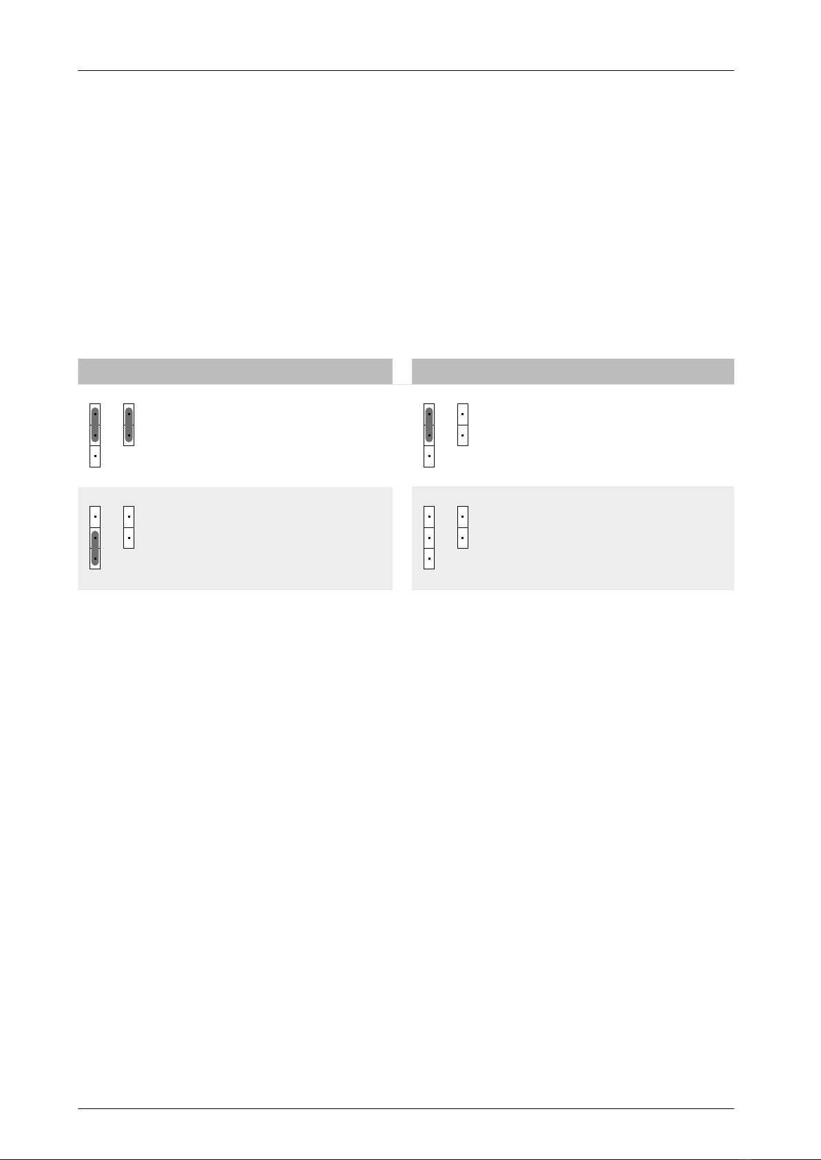
4.2.1 Pin headers S5 and S6
Type of electrical supply
The position of the jumpers on pin headers S5 and S6 determines the current type of electrical
supply.
S5 S6 Electrical supply via X1 S5 S6 Electrical supply via X5
Electrical supply via X/Y remote con-
trol bus
External electrical supply via terminals
X5-(+) and X5-(-)
Table 5: Type of electrical supply
Note
●If the CompTrol Interface is connected to a CompTrol Master via terminals X2 and X4, it must
be supplied with power via an external power supply unit.
●An external power supply unit is not included in the product package; see CompTrol Master
Technical Manual.
4.2.2 Electrical supply via X/Y remote control bus (terminal X1) for a CompTrol Interface
expansion module that is not in combination with a CompTrol Master expansion
module
The X/Y remote control bus is designed as a power bus with reverse polarity protection, and sup-
plies the CompTrol Interface with the required operating voltage (see “Table 5: Type of electrical
supply” on page 18). An external power supply unit is not required.
4.2.3 Electrical supply via terminal X5 for a CompTrol Interface expansion module
in combination with a CompTrol Master expansion module
When combined with a CompTrol Master, the CompTrol Interface must be supplied with the nec-
essary operating voltage via an external electrical supply (terminals X5-(+) and X5-(-)) (see “Ta-
ble 5: Type of electrical supply” on page 18). Terminal X5 does not have reverse polarity protec-
tion. An electrical supply via the X/Y remote control bus is not possible. An external power supply
unit is required.
4.3 Communication connections
The CompTrol Interface has two bus systems. The remote control, indoor unit, and CompTrol
Interface communicate with one another via the X/Y remote control bus X1 (terminals X1-X,
X1-Y). One CompTrol Master can communicate with a maximum of ve CompTrol Interfaces via
the CompTrol Interface bus (terminals X2, X4).
CompTrol Interface V4.0.x | Issue 21-05-2021 | 1000932 19
Product description
4.3.1 Pin headers S8 and S9
The position of the jumpers on pin headers S8 and S9 determines whether the CompTrol Inter-
face is in the middle or at the end of the CompTrol Interface bus. The pin headers only need to be
set if the CompTrol Interface is connected to a CompTrol Master (see CompTrol Master TM).
4.4 Types of connection
4.4.1 Analog input X3
An analog signal (4 to 20 mA, 0 to 20 mA, 0 to 5 V DC, or 0 to 10 V DC) at analog input X3-S
determines the temperature or frequency setpoint, depending on which program is selected.
The analog signal uses the ground connection X3-(-RV) as a reference.
The position of the jumpers on pin headers S4 and S7 determines the current analog signal type.
S4 S7 Analog signal type S4 S7 Analog signal type
4-20 mA 0-20 mA
0-10 V DC 0-5 V DC
Table 6: Analog signal type
The DC signal is evaluated proportionally at analog input X3-S. The referenced value tables are
program-dependent and described together with the corresponding program.
4.4.2 Digital inputs X2a to X2N
The assignment of digital inputs varies depending on the program, and largely determines the
behavior of the selected program.
All digital inputs are electrically isolated. The input voltage range is 20 V DC to 130 V DC or
24 V AC to 230 V AC. The current status of the digital inputs is indicated by LEDs (LD1 to LD6).
4.4.3 Digital outputs X4a to X4c
Each of the three digital outputs X4a-I, X4b-II, and X4c-III is designed as a volt-free relay contact.
They have a load capacity of 230 V AC/130 V DC, 0.5 A. The switched state of the relays is indi-
cated by LEDs (LD11 to LD13). A lit LED indicates that the corresponding relay is energized and
the contact is closed.
A relay’s switched state changes when the condition for a signal is met. You can congure which
signal is supplied at each output for your program using DIP switch S2-2. The switching function
of the relays can be inverted with DIP switch S2-6. See descriptions of the individual programs for
more details.

20 CompTrol Interface V4.0.x | Issue 21-05-2021 | 1000932
Product description
4.4.4 X/Y remote control bus X1
X1-X and X1-Y are the connection terminals for the X/Y remote control bus. This bus enables
communication between the remote control, indoor unit, and CompTrol Interface.
The X/Y remote control bus is designed as a power bus with reverse polarity protection, and sup-
plies the CompTrol Interface with the required operating voltage (see “4.2 CompTrol Interface
electrical supply” on page 18).
4.4.5 Bus connections X2 and X4
X2 and X4 are the bus connectors of the CompTrol Interface. Via this bus, the CompTrol Master
and a maximum of ve CompTrol Interfaces can communicate with one another (see CompTrol
Interface Technical Manual). Bus connections X2 and X4 form a serial I2C data bus.
4.4.6 External electrical supply X5
X5-(+) and X5-(-) are the connection terminals for the external electrical supply. Terminal X5 does
not have reverse polarity protection. This type of electrical supply is required if the CompTrol
Interface is connected to a CompTrol Master via terminals X2 and X4 (see “4.2 CompTrol Inter-
face electrical supply” on page 18).
4.5 DIP switch S1
DIP switch S1 is used to select the program, and also to set the installed outdoor unit model in
programs 8 and 9.
Note
●Only set DIP switches when they are disconnected from the electrical supply. Changed set-
tings only reliably become eective after a system restart. An exception here are DIP switches
S2-7 and S2-8, which govern the behavior of the 7-segment display. These DIP switches for
display behavior can also be set during ongoing operation.
●When reading the current DIP switch positions, bear in mind the horizontal installation posi-
tion of the CompTrol Interface! The ON switch setting is the one closest to the center of the
expansion module.
●Set inoperative DIP switches to OFF.
DIP switches S1-1 to S1-4 are used to set the desired program.
S1-1 S1-2 S1-3 S1-4 Program Designation
OFF OFF OFF OFF 0Temperature setpoint denition via analog signal
OFF ON OFF OFF 2Temperature setpoint denition with window contact
function
ON ON OFF OFF 3Temperature setpoint denition for equipment rooms
with temperature limit alarm
OFF OFF ON OFF 4Temperature setpoint denition with hotel remote control
function
ON OFF ON OFF 5Temperature setpoint denition with lockout function
OFF ON ON OFF 6Temperature setpoint denition for heat exchanger connec-
tion module
Table of contents


