AEM SM46 User manual

SPECIAL NOTICE
This product is now licensed to Anodyne Electronics Manufacturing (AEM) from Northern
Airborne Technology (NAT). AEM is responsible for all matters related to this product, including
sales, support and repair services.
Please note the transition to convert product manuals and supporting documentation is an
ongoing process and is being addressed on an ‘as needed’ basis.
All references to NAT product part numbers (and associated images) are equivalent to AEM
product part numbers.
Contact info:
Anodyne Electronics Manufacturing Corp.
#15-1925 Kirschner Road
Kelowna B.C. Canada
V1Y 4N7
Email: support@aem-corp.com
Toll Free: 1-888-763-1088
Phone: 1-250-763-1088
Fax: 1-250-763-1089
www.aem-corp.com
CONFIDENTIAL AND PROPRIETARY TO ANODYNE ELECTRONICS MANUFACTURING CORP.
INSTALLATION AND OPERATION MANUAL
Rev: 2.00 May 18, 2012
Anodyne Electronics Manufacturing Corp.
15-1925 Kirschner Road
Kelowna, BC, Canada.
V1Y 4N7
Telephone (250) 763-1088
Facsimile (250) 763-1089
Website: www.aem-corp.com
© 2012 Anodyne Electronics Manufacturing Corp. (AEM),
All Rights Reserved
SM46
N335 Series
Audio Controllers

N335 Series Audio Controller
SM46 Installation and Operation Manual
Installation and Operation Manual Page ii
ENG-FORM: 820-0100.DOTX
CONFIDENTIAL AND PROPRIETARY TO ANODYNE ELECTRONICS MANUFACTURING CORP.
COPYRIGHT STATEMENT
© 2012 Anodyne Electronics Manufacturing Corp. (AEM), All Rights Reserved
This publication is the property of AEM and is protected by Canadian copyright laws. No part of
this
document may be reproduced or transmitted in any form or by any means including electronic,
mechanical, photocopying, recording, or otherwise, without the prior written permission of AEM.
N335 Series Audio Controller
SM46 Installation and Operation Manual
Installation and Operation Manual Page iii
ENG-FORM: 820-0100.DOTX
CONFIDENTIAL AND PROPRIETARY TO ANODYNE ELECTRONICS MANUFACTURING CORP.
Prepared By:
Checked By:
Approved By:
The status of this installation and operation manual is controlled by the revision shown on the title page.
The status of each section is controlled by revision shown in the footer of each page. All revisions
affecting sections of this manual have been incorporated.
ISSUE/REVISION RECORD
Manual Issue
Number
Section
Revision Number
Revision Description
Issue Date
4.21
Section 1 Rev: 1.00
Section 2 Rev: 1.00
Section 3 Rev: 1.00
New Format
Apr 14, 2009
AEM MANUAL REVISIONS
Section
Revision Number
Revision Description
Date
All Rev 2.00 Updated template
May 18, 2012
Tony Pearson
Designer
May 18, 2012
Loen Clement
Designer
Jun 26/12
Tom Betzelt
Product Support
Manager
June 26, 2012

N335 Series Audio Controller
SM46 Installation and Operation Manual
Installation and Operation Manual Page iv
ENG-FORM: 820-0100.DOTX
CONFIDENTIAL AND PROPRIETARY TO ANODYNE ELECTRONICS MANUFACTURING CORP.
Table of Contents
Section Title Page
1.0 Description
1.1 Introduction 1-1
1.2 Product Description 1-1
1.3 Design Features 1-1
1.4 Specifications 1-2
1.4.1 Electrical Specifications 1-2
1.4.2 Physical Specifications 1-5
1.4.3 Environmental Specifications 1-6
1.4.4 Product Approval 1-6
1.5 Unit Nomenclature 1-6
2.0 Installation
2.1 Introduction 2-1
2.2 Unpacking and Inspection 2-1
2.2.1 Warranty 2-1
2.3 Continued Airworthiness 2-1
2.4 Installation Procedures 2-1
2.4.1 Warnings 2-2
2.4.2 Cautions 2-2
2.4.3 Cabling and Wiring 2-3
2.4.4 Tie Lines 2-3
2.4.5 Mechanical Mounting 2-3
2.4.6 Post Installation Checks 2-4
2.5 Adjustments and Connections 2-5
2.5.1 Left side Adjustments 2-5
2.5.2 Right Side Adjustments 2-5
2.5.3 Adjustment Options 2-5
2.6 Accessories Required But Not Supplied 2-6
2.7 Installation Drawings 2-6
3.0 Operation
3.1 Introduction 3-1
3.2 General Information 3-1
3.3 Controls and Indicators 3-1
3.3.1 Receiver Input Controls (N335-001 and -201 only) 3-2
3.3.2 Transceiver Input Controls 3-2
3.3.3 Transmit Selection 3-3
3.3.4 Emergency Switch 3-3
3.3.5 CALL 3-4
3.3.6 Miscellaneous Controls 3-4

N335 Series Audio Controller
SM46 Installation and Operation Manual
May 18, 2012 Rev: 2.00 Page 1-1
ENG-FORM: 800-0100.DOTX
CONFIDENTIAL AND PROPRIETARY TO ANODYNE ELECTRONICS MANUFACTURING CORP.
Section 1.0 Description
1.1 Introduction
Information in this section consists of product description, design features and specifications for N335-
001, N335-002, N335-201, and N335-202 Audio Controllers. All derivative product information shall be
contained in the applicable manual supplement, which may be obtained from AEM as required. Review
all notes, warning and cautions.
1.2 Purpose of Equipment
The N335 audio controllers are compatible with military and civil aviation headsets. The N335 controls the
audio from multiple receivers, and allows transmission of mic audio to a selected transmitter. VOX intercom
operation is also proved on a proprietary tie line to multiple units. A fully redundant backup system is selectable
from the front panel, and a CVR output is provided.
1.3 Design Features
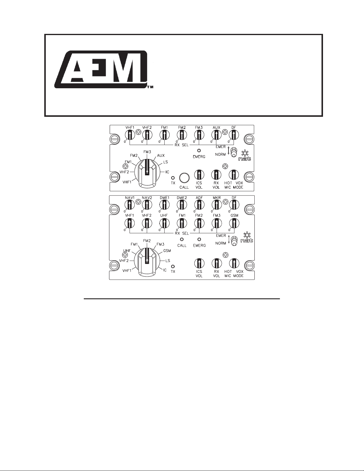
The N335 is a Dzus rail mounted audio controller with various faceplate lighting options. The N335 has a
composite Radio Audio output to provide monitoring capabilities for additional users. It can be configured
in the field to suit various commercial and military headsets, and microphone outputs. Receive Audio
inputs and Direct Audio inputs are adjustable to suit installation requirements. Emergency mode
operation provides switching to a fully redundant back-up system that provides full performance. A front
panel annunciator provides indication that the EMER mode is active.
N335-001 The N225-001 Audio Controller has a NVIS Green ‘A’ lighted front panel. It
provides radio transmit and receive audio select capability for the cockpit position.
It will support four microphone types a standard –dynamic 5-ohm, dynamic 75-
ohm, dynamic 150-ohm and amplified dynamic 150-ohm types. It provides NAT
ICS tie line capability from 1 to 4 loads. Transmit capability is provided for two
users (user 1 and user 2), and an annunciator on the front panel indicates
transmit status. It provides common intercom functions for up to two headset
stations, and allows for intercom capability to other audio controllers via an ICS
Tie Line. A CALL annunciator advises the operator that other users in the system
need to communicate, if they are in an ‘isolate’ mode.
N335-002 The N335-002 Audio Controller has an NVIS Green ‘A’ lighted front panel. It
provides radio transmit and receive audio select capability for the Crew position.
The crew position is restricted in its radio capability to the ‘communication’ radios.
It also provides common intercom functions for up to two headset stations, and
allows intercom capability to other audio controllers via the ICS Tie Line. A CALL
switch allows the operator to signal other users in the system that they need to
communicate, if they are in an ‘isolate’ mode.

N335 Series Audio Controller
SM46 Installation and Operation Manual
May 18, 2012 Rev: 2.00 Page 1-2
ENG-FORM: 800-0100.DOTX
CONFIDENTIAL AND PROPRIETARY TO ANODYNE ELECTRONICS MANUFACTURING CORP.
N335-201
The N335-201 Audio Controller is identical to the N335-001, but with ‘deadfront’
CALL, EMEER and TX text annunciators on the front panel. It will support only
two microphone types as standard
–dynamic 5 ohm and amplified-
dynamic 150
ohm. It provides
NAT
ICS tie line capability from 2 to 4 loads, with one switch
position functioning to enable Super
NAT
ICS tie line operation, which maintains
the rated output level independent of the number of units connected to the tie
line. It may be configured to provide auto emergency power mode switchover,
ICS tie line muting during transmit, and pilot over copilot transmit priority.
N335-202
The N335-202 Audio Controller is identical to the N335-002, but with ‘deadfront’
text annunciators on the front panel. It will support only two microphone types as
standard
–dynamic 5-ohm and amplified dynamic 150 ohm. It provides NAT
ICS
tie line capability from 2 to 4 loads, with one switch position functioning to enable
Super
NAT
ICS tie line operation, which maintains the rated output level
independent of the number of units connected to the tie line. It may be
configured to provide auto emergency power mode switchover, ICS tie line
muting during transmit, and pilot over co-pilot transmit priority.
1.4 Specifications
1.4.1 Electrical Specifications
Power Supply: Multiple switchers and linear regulators with reverse and
over voltage protection.
Normal Operating Conditions:
Nominal Operating Voltage: 27.5 Vdc
Maximum Operating Voltage: 30.3 Vdc
Minimum Operating Voltage: 24.8 Vdc
Emergency Operating Voltage: 10.0 Vdc
Other:
Lighting:
N335-001 400 mA @ 27.5 Vdc max.
N335-002 300 mA @ 27.5 Vdc max
N335-201 550 mA @ 27.5 Vdc max
N335-202 425 mA @ 27.5 Vdc max
Input current:
N335-001/002 500 mA @ 27.5 Vdc max
N335-201/202 750 mA @ 27.5 Vdc max
Input Signals:
Quantity: 15 Receive channels (N335-001 and -201)
8 Receive channels (N335-002 and -202)
2 Mic channels
6 Direct channels
1 Call annunciator (N335-001 and -201)
2 transmit PTT key inputs
2 ICS PTT key inputs

N335 Series Audio Controller
SM46 Installation and Operation Manual
May 18, 2012 Rev: 2.00 Page 1-3
ENG-FORM: 800-0100.DOTX
CONFIDENTIAL AND PROPRIETARY TO ANODYNE ELECTRONICS MANUFACTURING CORP.
Audio level: 1 –10 Vrms for receiver inputs
(Internally selectable gain switches)
1–10 Vrms for direct inputs
(Internally selectable gain switches)
0.25 Vrms for Amplified 150 :mic input
1.1 mVrms for Dynamic 150 :mic input
(N335-001 and -002 only)
0.850 mVrms for Dynamic 75 :mic input
(N335-001 and -002 only)
0.250 mVrms for Dynamic 5 :mic input
Transmit PTT (-00x) <10 mA input current, active low (3 Vdc max.)
(-20x) <75 mA input current, active low (3 Vdc max.)
ICS PTT (-00x) <25 mA input current, active low (3 Vdc max.)
(-20x) <25 mA input current, active low (3 Vdc max.)
CALL annunciator (-001 only) <10 mA input current, active low (3 Vdc max.)
CALL annunciator (-201 only) <50 mA input current, active low (3 Vdc max.)
Impedance: 1 k:r10% for Receive and Direct inputs
150 :r10% for Amplified-dynamic 150 :mic input
150 :r10% for Dynamic 150 :mic input
(N335-001 and -002 only)
75 :r10% for Dynamic 75 :mic input
(N335-001 and -002 only)
5:r2:for Dynamic 5 :mic input
(N335-001 and -002 only)
5:r2:for Dynamic 5 :mic input
(N335-001 and -002 only)
Circuitry Type: All audio inputs are balanced except for the 150 :
amplified dynamic mic input
Coupling: < -60 dB input to input crosstalk
Output Signals:
Quantity: 2 Phones outputs
8 Transmitter mic outputs (N335-001 and -201 only)
7 Transmitter mic outputs (N335-001 and -201 only)
8 Transmitter keyline outputs(N335-001 and -201 only)
7 Transmitter keyline outputs(N335-001 and -201 only)
1 CVR output
1 Composite Receive Audio output
1 CALL switch output (N335-002 and -202 only)

N335 Series Audio Controller
SM46 Installation and Operation Manual
May 18, 2012 Rev: 2.00 Page 1-4
ENG-FORM: 800-0100.DOTX
CONFIDENTIAL AND PROPRIETARY TO ANODYNE ELECTRONICS MANUFACTURING CORP.
Rated level: >15.5 Vrms or 400 mW for 600 :phones output
>7.7 Vrms or 400 mW for 150 :phones output
>1.8 Vrms or 400 mW for 8 :phones output
0.1 -1 Vrms for TX Mic output (250 mVrms nominal)
>450 mVrms into 5 k:for CVR output with TX selector
set to IC, or ICS VOL control fully ccw (>70 mVrms into
5 k:for other TX selector / ICS VOL control positions).
> 2.5 Vrms to 600 :Composite Receive output
1 A / 0.5 :max Transmitter keyline output
100 mA max sink current for CALL switch output.
(N335-001 and -002 only)
Rated Impedance: 100 :r10% for TX Mic output
5 k:r10% for CVR output
600 :r10% for Composite Receive output
Circuitry Type: Phones, CVR, Microphone and Composite RX outputs are
transformer outputs
The CVR output is composed of both mic inputs and user #1
phones output
Frequency Response: Headphone Outputs:
Receive inputs <3 dB from 350 Hz to 6000 Hz
Direct inputs <3 dB from 350 Hz to 6000 Hz
Intercom <3 dB from 350 Hz to 3000 Hz
TX Mic output: <3 dB from 350 Hz to 6000 Hz
CVR output:
SuperNAT input: <3 dB from 350 Hz to 3000 Hz
(N335-20x only)
All other inputs <3 dB from 350 to 6000 Hz
Composite RX output: <3 dB from 350 to 6000 Hz
Distortion: < 4% THD @ Rated power output
Audio Noise Level Without Signal: > 60 dB down from rated output
Coupling: < -55 dB input to output crosstalk
Output Regulation at 400% and 75% of rated load:
< 10% distortion / '7 dB max. of rated output power
N335 Series Audio Controller
SM46 Installation and Operation Manual
May 18, 2012 Rev: 2.00 Page 1-5
ENG-FORM: 800-0100.DOTX
CONFIDENTIAL AND PROPRIETARY TO ANODYNE ELECTRONICS MANUFACTURING CORP.
Bi-directional:
Quantity: 1 ICS tie channel*
Rated level: 340 ±50 mVrms for NAT ICS tie (1 load)
(N335-001 and -002 only)
230 ±40 mVrms for NAT ICS tie (2 loads)
170 ±30 mVrms for NAT ICS tie (3 loads)
135 ±20 mVrms for NAT ICS tie (4 loads)
1.2 ±0.2 Vrms for SuperNAT ICS tie (2-4 loads)
(N335-201 and -202 only)
Rated Impedance: 1.8 k:r10% for NAT ICS tie input
1.8 k:r10% for SuperNAT ICS tie
(N335-201 and -202 only)
Circuitry Type: Balanced
*Default configuration is NAT ICS tie –4 loads (135 ± 20 mVrms, 1.8 k:± 10%)
Annunciators:
(N335-00x) CALL LED illuminates when activated (N335-001 only)
EMER LED illuminates when activated
TX LED illuminates when activated
(N335-20x) CALL annunciator text illuminates when activated
EMERG annunciator text illuminates when activated
TX annuciator text illuminates when activated
Dimming Threshold:
(N335-00x) 5.25 r1.5 Vdc (+28 VDC LIGHTS input)
(N335-20x) 11.5 ±3.25 Vdc (+28 VDC LIGHTS input)
1.4.2 Physical Specifications
N335-001
N335-002
N335-201
N335-202
Height
3.4” (87 mm)
2.63” (67 mm)
3.4” (87 mm)
2.63” (67 mm)
Depth
6.2” (158 mm)
6.2” (158 mm)
6.2” (158 mm)
6.2” (158 mm)
Width
5.0” (127 mm)
5.0” (127 mm)
5.0” (127 mm)
5.0” (127 mm)
Weight
3.5 lbs (1.6 kg)
2.9 lbs (1.3 kg)
3.6 lbs (1.6 kg)
3.0 lbs (1.4 kg)
Mounting Dzus Rail, four fasteners
(N335-001/-201) 2.25” vertical spacing
(N335-002/-202) 1.5” vertical spacing
Faceplate Laser-engravedacrylic edge lit panel NVIS green ‘A’
(N335-00x) NVIS green ‘A’ Friendly
(N335-20x) NVIS green ‘A’ Compliant

N335 Series Audio Controller
SM46 Installation and Operation Manual
May 18, 2012 Rev: 2.00 Page 1-6
ENG-FORM: 800-0100.DOTX
CONFIDENTIAL AND PROPRIETARY TO ANODYNE ELECTRONICS MANUFACTURING CORP.
Finish/Material
(N335-00x) Chassis –5052-H32 brushed aluminum with conversion
coating finish
Cover is 1100-H19 aluminum with anodized black
lettering
(N335-20x) Chassis and cover are 5052-H32 brushed aluminum with
conversion coating finish
Connectors One male 50-pin filtered D-subminiature connector
utilizing lock posts
One male 50-pin and one male 15-pin filtered
D-subminiature connector utilizing jack posts
Installation kit N335-IKC (D50S50S15SL-IKC)
1.4.3 Environmental Specifications
Operating Temperature -45qC. to +70qC
Survival Temperatures -55qC. to +85qC
Vibration/Shock DO-160C Cat. N/P
Humidity 95%
Altitude 35,000 feet max
1.4.4 Product Approval
Compliance: N335-00x DO-160C Env. Cat. C4 –BB[NP]XXXXFXABABXVAXXX
N335-20x DO-160C Env. Cat. C4 –BB[NP]XXXXFXABABZVAXXX
1.5 Unit Nomenclature
N335-001
14 user-adjustable receive audio level controls
Support for two users
ICS Call annunciation
Composite receive audio output
High
Crosstalk filtering
Complete redundant Emergency circuit
Suitable for High or Low impedance systems
8 TX selections
6 direct inputs
3 ICS modes
–LIVE/KEYED/VOX
CVR output
NVIS friendly with LED annunicators

N335 Series Audio Controller
SM46 Installation and Operation Manual
May 18, 2012 Rev: 2.00 Page 1-7
ENG-FORM: 800-0100.DOTX
CONFIDENTIAL AND PROPRIETARY TO ANODYNE ELECTRONICS MANUFACTURING CORP.
N335-002
7 user-adjustable receive audio level controls
Support for two users
ICS Call annunciation
Composite receive audio output
High Crosstalk filtering
Complete redundant Emergency circuit
Suitable for High or Low impedance systems
7 TX selections
6 direct inputs
3 ICS modes
–LIVE/KEYED/VOX
CVR
output
NVIS friendly with LED annunciators
N335-201
14 user-adjustable receive audio level controls
Support for two users
ICS Call annunciation
Composite receive audio output
High Crosstalk filtering
Complete redundant Emergency circuit
Suitable for High
or Low impedance systems
8 TX selections
6 direct inputs
3 ICS modes
–LIVE/KEYED/VOX
CVR output
Super
NAT ICS tie
Selectable Auto
-Emergency mode
Tie
-line muting during TX
Pilot TX priority
NVIS compliant with dead front text annunciators
N335-202
7 user-adjustable receive audio level controls
Support for two users
ICS Call annunciation
Composite receive audio output
High Crosstalk filtering
Complete redundant Emergency circuit
Suitable for High or Low impedance systems
7 TX selections
6 direct inputs
3 ICS modes
–LIVE/KEYED/VOX
CVR output
Super
NAT ICS tie
Selectable Auto
-Emergency mode
Tie
-line muting during TX
Pilot TX priority
NVIS compliant with dead front text annunciators
End of Section 1.0

N335 Series Audio Controller
SM46 Installation and Operation Manual
May 18, 2012 Rev: 2.00 Page 2-1
ENG-FORM: 805-0100.DOTX
CONFIDENTIAL AND PROPRIETARY TO ANODYNE ELECTRONICS MANUFACTURING CORP.
Section 2.0 Installation
2.1 Introduction
Information in this section consists of unpacking and inspection procedures, installation procedures, post-
installation checks and installation drawings for the N335 Series Audio Controller.
Review all notes, warnings and cautions.
2.2 Unpacking and Inspection
Unpack the equipment carefully. Inspect the unit visually for damage due to shipping and report all such
claims immediately to the carrier involved. Note that each unit should have the following:
- N335 Series Audio Controller
- Product Information Card
- Certificate of Conformity or Release certification
Verify that all items are present before proceeding and report any shortage immediately to your supplier.
2.2.1 Warranty
All Anodyne Electronics Manufacturing Corp. (AEM) products are warranted for 2 years. See the website
www.aem-corp.com/warranty for complete details.
2.3 Continued Airworthiness
Maintenance of the N335 Dual User Audio Controllers is ‘on condition’ only. Periodic maintenance of
these products is not required.
2.4 Installation Procedures
Installation Notice
The installation requirements for this product are subject to change without notice. This may affect wiring,
cable and connector configurations. The factory must be consulted for the latest product installation
requirements. All risk associated with this equipment installation contrary to the factory instructions shall
be the responsibility of the end user or installing agency.

N335 Series Audio Controller
SM46 Installation and Operation Manual
May 18, 2012 Rev: 2.00 Page 2-2
ENG-FORM: 805-0100.DOTX
CONFIDENTIAL AND PROPRIETARY TO ANODYNE ELECTRONICS MANUFACTURING CORP.
2.4.1 Warnings
WARNING:
High volume settings can cause hearing damage.
Set the headset volume control to the minimum volume setting prior to
conducting tests, and slowly increase the headset volume to a
comfortable listening level.
2.4.2 Cautions
CAUTION:
Do not remove compone
nts from the product while the unit is turned on. This
could cause damage to the component or unit.
Do not bundle any lines from this unit
with transmitter coax lines. Do not
bundle any logic, audio, or DC power lines from this unit with 400 Hz synchro
wi
ring or AC power lines. Do not position this unit next to any device with a
strong alternat
ing magnetic field such as an inverter, motor or blower, or
significant audio interference will result.
In all installations, use shielded cable exactly as shown,
and ground as indicated
.
Significant problems may result from not following these guidelines.
All audio installations can be seriously degraded byincorrect wiring and shielding, and
may result in abnormal cross
-talk, hum and ground-loop noise. Be especi
ally careful
with all microphone wiring and tie line wiring, as these lines carry the lowest level
signals in the aircraft.
The intercom tie lines should also be properly termi
nated with either the
appropriate number of additional units, or with a load
resistor. See section
2.
4.4, Tie Lines.
In all installations that use the Dynamic microphone capability of the N335,
extreme care must be taken with the shielding and routing of the microphone
wiring. This is especially true of the 5
-ohm Dynamic mic inp
ut, where typical
signals are in the range of 100
-250 μVrms. Special wire with Mumetal
shielding should be considered if there are any concerns about installation
-
related noise.
Do not bundle the microphone wiring with high-level lines
(headphone, radio
audio, coaxial cables, etc.).
Headset and/or helmet wiring may also need to be reviewed if using Dynamic
microphones. Many of the headsets and helmets on the market have minimal
shielding for the wiring associated with the mic and phone circuits. Those with
shielded wiring often use the Phone Lo connection for the shield ground. In the
N335, the Phone Lo connection is not ground referenced, so the shielding has
no effect. This will result in substantial coupling of the Phone signal onto the
Microphone wires, leading to high levels of crosstalk in the intercom system.
These shielding considerations also apply to in
-
line PTT cordsets. If a review
of the headset wiring indicates there will be a problem with the shield
termi
nation, it is acceptable to ground the Phone Lo connection to a local
ground at the headset jack/connector.

N335 Series Audio Controller
SM46 Installation and Operation Manual
May 18, 2012 Rev: 2.00 Page 2-3
ENG-FORM: 805-0100.DOTX
CONFIDENTIAL AND PROPRIETARY TO ANODYNE ELECTRONICS MANUFACTURING CORP.
2.4.3 Cabling and Wiring
All wire shall be selected in accordance with the original aircraft manufacturer's Maintenance Instructions
or AC43.13-1B Change 1, Paragraphs 11-76 through 11-78. Unshielded wire types shall qualify to
MIL-W-22759 as specified in AC43.13-1B Change 1, Paragraphs 11-85, 11-86, and listed in Table 11-11.
For shielded wire applications, use Tefzel MIL-C-27500 shielded wire with solder sleeves (for shield
terminations) to make the most compact and easily terminated interconnect. Follow the connector map in
Section 2.7 as required.
Allow 3" from the end of the shielded wiring to the shield termination to allow the connector hood to be
easily installed. Reference the interconnect drawing in Section 2.7 for shield termination details. Note that
the hood is a "clamshell" hood, and is installed after the wiring is complete. Aircraft harnessing shall
permit the unit to be removed from the panel for easy access to all side adjustments. Do NOT mount the
unit until all adjustments have been performed.
Maintain wire segregation and route wiring in accordance with the original aircraft manufacturers
Maintenance Instructions.
Unless otherwise noted, all wiring shall be a minimum of 22 AWG, except power and ground lines, which
shall be a minimum of 20 AWG. Reference the Interconnect drawing for additional specifications. Check
that the ground connection is clean and well secured, and that it shares no path with any electrically noisy
aircraft accessories such as blowers, turn and bank instruments or similar loads. Power to this unit must
be supplied from a separate circuit breaker or fuse (fast blow), and not attached to any other circuit
breaker without additional protection. Verify that the selected circuit breaker size and wire gauge are
adequate for the installation using the techniques specified in AC43.13-1B Change 1, Paragraphs 11-47
through 11-51 and 11-66 through 11-69.
2.4.4 Tie Lines
2.4.4.1 N335-001/-002
When no other unit is to be connected to the tie-line, set the ICS TIE ADJUST switch to the '1 NAT LOAD'
position (position 1), and connect a 1.8 k:resistor between the ICS TIE HI and ICS TIE LO lines (refer to
the appropriate drawings listed in section 2.7).
2.4.4.2 N335-201/-202
When no other units are to be connected to the tie-line, set the SUPER TIE SELECT switch to the 'NAT
TIE' position (position 0), set the NAT TIE SELECT switch to the '2 NAT LOADS' position (position 1), and
connect a 910 :resistor between the ICS TIE HI and ICS TIE LO lines (refer to the appropriate drawings
listed in section 2.7).
2.4.5 Mechanical Mounting
The N335 can be mounted vertically or horizontally in standard Dzus rails.
Before the unit is mounted, make all functional tests, and trimpot adjustments. Be sure the harness has
enough clearance to permit the unit to be pulled out for re-adjustment, if needed later. Make sure unit is
securely fastened to the Dzus rail, and that the connector locks are tightened before any flight is
attempted.

N335 Series Audio Controller
SM46 Installation and Operation Manual
May 18, 2012 Rev: 2.00 Page 2-4
ENG-FORM: 805-0100.DOTX
CONFIDENTIAL AND PROPRIETARY TO ANODYNE ELECTRONICS MANUFACTURING CORP.
2.4.6 Post Installation Checks
WARNING:
High volume settings can cause hearing damage.
Set the headset volume control to the minimum volume setting prior to
conducting audio tests, and slowly increase the headset volume to a
comfortable listening level.
2.4.6.1 Voltage/Resistance Checks
These instructions apply to all N335 models unless otherwise indicated. Do not attach the N335 until the
following conditions are met.
Check the following:
a) P102 pins <1>, <2> and <8> for +28 Vdc relative to ground.
b) P102 pins <3>, <9>, <10> and <11> for continuity to ground.
2.4.6.2 Power On Checks
Power up the aircraft’s systems and confirm normal operation of all functions of the N335. Refer to
Section 3 (Operation) for specific operational details.
a) Turn on the radios and accessories required for the system.
b) Check for correct radio audio and adjust for acceptable level.
c) Run through all installed functions, and check the ICS and TX functions for all users. Refer to
Section 3 for specific operation details.
Notes: Significantly different headsets may have different mic characteristics.
The David Clark M-7 mic is much more active than the M-4 or M-1 mics, and may
aggravate headset imbalance if used in a mixed system.
d) If any preset requires adjustment, be sure this is carried out before the aircraft leaves, and that
the unit and its mating connector are secured before departure. Make all required log book
entries, electrical load, weight and balance amendments and other paperwork as required by your
local regulatory agency.
Note: The unit is shipped from the factory with all internal adjustments set to the normal test levels. Once
installed in the aircraft, it may be desirable to change some of these settings to best suit the local
operating environment. See Section 2.5 for adjustment information.
Upon satisfactory completion of all performance checks, make all required log book entries, electrical
load, weight and balance amendments and other documentation as required by your local regulatory
agency before releasing the aircraft for service.

N335 Series Audio Controller
SM46 Installation and Operation Manual
May 18, 2012 Rev: 2.00 Page 2-5
ENG-FORM: 805-0100.DOTX
CONFIDENTIAL AND PROPRIETARY TO ANODYNE ELECTRONICS MANUFACTURING CORP.
2.5 Adjustments and Connections
The internal adjustments that can be varied are located along the sides of the unit (refer to the drawings
listed below, where xxx refers to the specific unit). The cover must be removed to access the necessary
switches and trimpots. On the drawings, an asterisk (*) against the relevant values indicates the factory
settings.
2.5.1 Left side Adjustments
Refer to the relevant drawing (N335\xxx\404-0) for all adjustments.
2.5.2 Right Side Adjustments
Refer to the relevant drawing (N335\xxx\404-1) for all adjustments.
2.5.3 Adjustment Options
The available adjustments are listed below. The locations and options may vary from model to model;
check the appropriate drawing (sections 2.5.1 and 2.5.2) for the unit under consideration. Some of these
adjustments, indicated by an asterisk (*), are available on the N335-2xx models only.
NAT Tie Select / ICS Tie Adjust: selects the gain of the intercom channel for incoming ICS tie audio to
match the number of units connected to the tie line.
*Super Tie Select: selects the gain of the intercom channel for outgoing ICS tie audio to maintain the
rated O/P level independent of the number of units connected to the tie line.
RX Input Level: selects the input level for each RX input to match the radio output level.
TX Mic Output: provides for adjustment of each TX mic output to match the radio mic input requirements.
LS Volume Adjust: provides for adjustment of the loudspeaker volume level.
CVR Adjust: provides for adjustment of the CVR audio output level.
VOX Delay Adjust: provides for adjustment of the VOX delay associated with the #1 and #2 microphone
circuits.
MIC/MIC Impedance: provides for adjustment of microphone gain, input impedance, and bias.
ALC: provides for adjustment of the automatic level control set point associated with the #1 and #2
microphone circuits.
Output Impedance: provides for adjustment of phones output impedance associated with the #1 and #2
headphone circuits.
*Auto Emergency: provides for selection of automatic emergency power switchover.
*Tie Line Mute: provides for selection of incoming tie line audio muting during transmit.
*PLT TX Priority: provides for selection of user #1 priority over user #2 during transmit.

N335 Series Audio Controller
SM46 Installation and Operation Manual
May 18, 2012 Rev: 2.00 Page 2-6
ENG-FORM: 805-0100.DOTX
CONFIDENTIAL AND PROPRIETARY TO ANODYNE ELECTRONICS MANUFACTURING CORP.
2.6 Accessories Required But Not Supplied
Installation kit p/n N335-IKC (crimp) is required to complete the installation. The kit (AEM Part No.
D50S50S15SL-IKC) consists of 2 x D50SL-IKC and 1 x D15SL-IKC.
D50SL-IKC consists of:
Quantity Description AEM Part No
1 D-min 50 Socket Housing 20-21-050
50 MS Crimp Socket 20-26-901
1* Jack Screw Set 20-27-002
1* Lock Clip Set 20-27-004
1 50 Pin Connector Hood 20-29-051
D15SL-IKC consists of:
Quantity Description AEM Part No
1 D-min 15 Socket Housing 20-21-015
15 MS Crimp Socket 20-26-901
1* Jack Screw Set 20-27-002
1* Lock Clip Set 20-27-004
1 15 Pin Connector Hood 20-29-015
* Use as required.
2.7 Installation Drawings
DRAWING
REV.
DESCRIPTION
TYPE
N335-001
N335\001\403-0
1.01
Dual User Audio Controller
Interconnect
N335\001\403-1
1.01
Dual User Audio Controller
Interconnect
N335\001\403-2
1.01
Dual User Audio Controller
Interconnect
N335\001\404-0
1.00
Left Side View
Options
N335\001\404-1
1.00
Right Side View
Options
N335\001\405-0
1.01
Dual User Audio Controller
Connector Map
N335\001\905-0
1.00
Audio Controller
Faceplate
N335\001\922-0
1.00
Audio Controller
Mechanical Installation
N335-002
N335\002\403-0
1.01
Dual User Audio Controller
Interconnect
N335\002\403-1
1.01
Dual User Audio Controller
Interconnect
N335\002\403-2
1.01
Dual User Audio Controller
Interconnect
N335\002\404-0
1.10
Left Side View
Options
N335\002\404-1
1.00
Right Side View
Options
N335\002\405-0
1.01
Dual User Audio Controller
Connector Map
N335\002\905-0
1.00
Audio Controller
Faceplate
N335\002\922-0
1.10
Audio Controller
Mechanical Installation

N335 Series Audio Controller
SM46 Installation and Operation Manual
May 18, 2012 Rev: 2.00 Page 2-7
ENG-FORM: 805-0100.DOTX
CONFIDENTIAL AND PROPRIETARY TO ANODYNE ELECTRONICS MANUFACTURING CORP.
DRAWING
REV.
DESCRIPTION
TYPE
N335-201
N335\201\403-0
1.00
Audio Controller
Interconnect
N335\201\403-1
1.00
Audio Controller
Interconnect
N335\201\403-2
1.00
Audio Controller
Interconnect
N335\201\404-0
1.00
Left Side View
Options
N335\201\404-1
1.00
Right Side View
Options
N335\201\405-0
1.00
Audio Controller
Connector Map
N335\201\905-0
1.00
Audio Controller
Faceplate
N335\201\922-0
1.00
Audio Controller
Mechanical Installation
N335-202
N335\202\403-0
1.00
Audio Controller
Interconnect
N335\202\403-1
1.00
Audio Controller
Interconnect
N335\202\403-2
1.00
Audio Controller
Interconnect
N335\202\404-0
1.00
Left Side View
Options
N335\202\404-1
1.00
Right Side View
Options
N335\202\405-0
1.00
Audio Controller
Connector Map
N335\202\905-0
1.00
Audio Controller
Faceplate
N335\202\922-0
1.00
Audio Controller
Mechanical Installation
Section 2.0 ends following above documents
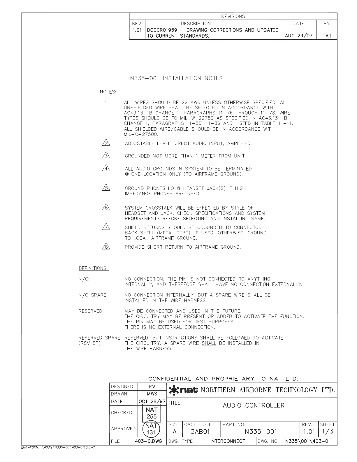
Table of contents
Other AEM Recording Equipment manuals


Popular Recording Equipment manuals by other brands

MODEL SOUNDS
MODEL SOUNDS DopplerFX Reference manual

M-Audio
M-Audio ProSessions 24 Bunker 8 manual

SMC Networks
SMC Networks EX600-SEN1 Installation & maintenance manual

Leviton
Leviton Plug-In Serial Interface Module RZCP installation instructions

Behringer
Behringer MIDI FOOT CONTROLLER FCB1010 manual

Digital Voice Systems
Digital Voice Systems AMBE-3000 HDK user manual


